Geosynthetic Subsurface Drainage Systems For Pavements ...
Geosynthetic Subsurface Drainage Systems For Pavements ...
Geosynthetic Subsurface Drainage Systems For Pavements ...

Create successful ePaper yourself
Turn your PDF publications into a flip-book with our unique Google optimized e-Paper software.
<strong>Geosynthetic</strong> <strong>Subsurface</strong><br />
<strong>Drainage</strong> <strong>Systems</strong> <strong>For</strong><br />
<strong>Pavements</strong><br />
Foundation Performance<br />
Association<br />
January 10, 2007
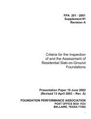
CONVENTIONAL FLEXIBLE<br />
PAVEMENTS<br />
Seal Coat Tack Coat<br />
Surface Course<br />
Binder Course<br />
Base Course<br />
Subbase<br />
Compacted Subgrade<br />
Natural Subgrade
MECHANISTIC-EMPIRICAL FRAMEWORK IN<br />
THE 2002 PAVEMENT DESIGN GUIDE.
Related References<br />
FHWA, 1992, Demonstration project 87: “Drainable pavement systems”, Participant<br />
Notebook, FHWA-SA-92-008.<br />
US Army Corps of Engineers, 1992, “Engineering and design drainage layers for<br />
pavements”, Engineer Technical Letter, 1110-3-435, Department of Army.<br />
Cedergren, 1987, “<strong>Drainage</strong> of highway and airfield pavements”, R. E. Krieger<br />
publishing Co, FL<br />
Christopher and McGuffey, 1997, NCHRP Synthesis of highway practice 239,<br />
“Pavement subsurface drainage systems”, Transportation Research Board.<br />
Christopher, Hayden, and Zhao, 1999, “Roadway Base and Subgrade Geocomposite<br />
<strong>Drainage</strong> Layers, “ ASTM STP 1390, American Society for Testing and Materials, June.<br />
Christopher and Zhao, 2001, “Design manual for roadway geocomposite underdrain<br />
systems”, Tenax Corporation.
Water<br />
in the<br />
Pavement<br />
Structure<br />
Primary<br />
Cause of<br />
Distress
Water in Pavement <strong>Systems</strong><br />
AASHTO (1993) reports:<br />
Water in the asphalt surface<br />
Moisture damage, modulus reduction and loss of tensile strength<br />
Saturation reduces dry modulus of the asphalt ∃ 30 %<br />
Moisture in unbound aggregate base and subbase<br />
Loss of stiffness ∃ 50 %<br />
Water in asphalt-treated base<br />
Modulus reduction of up to 30 percent<br />
Increase erosion susceptibility of cement or lime treated bases<br />
Saturated fine grained roadbed soil<br />
Modulus reductions ∃ 50 %
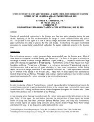
100<br />
80<br />
60<br />
40<br />
20<br />
0<br />
S = Severity Factor<br />
S=5<br />
S=10<br />
S=20<br />
0 10 20 30 40 50<br />
% of Time Structural Section is Saturated<br />
Severity factor<br />
measures<br />
the relative<br />
damage<br />
between wet<br />
and dry periods<br />
<strong>For</strong> a pavement section with a moderate severity factor of 10, if 10% of time<br />
the pavement is approaching saturation, the pavement service life could be<br />
reduced by half.<br />
Ref. Cedergren, H.R. 1987, <strong>Drainage</strong> of highway and airfield pavements, Robert E Krieger Publishing Co, FL.
Tire<br />
Tire<br />
Subgrade Subgrade<br />
DRAINAGE
CONTAMINATION/ PUMPING<br />
Subgrade<br />
HMA<br />
Base
AGGREGATE PENETRATION<br />
Subgrade<br />
HMA<br />
Base
JOINT DETERIORATION
Water in <strong>Pavements</strong> Summary<br />
Stripping in HMA<br />
Loss of Subgrade Support<br />
Reduction of Granular Layer<br />
Stiffness<br />
Erosion of Cement-Treated Base<br />
Layers<br />
Reduction in the Pavement Service<br />
Life If Base Is Saturated for<br />
Sometime<br />
Debond between Layers
HOW TO ADDRESS THE PROBLEM?<br />
Pavement geometry (slopes and ditches)<br />
Crack sealing<br />
Treated Layer<br />
Thicker Layers<br />
Full Width<br />
<strong>Subsurface</strong> <strong>Drainage</strong> 0.02 m/m 0.04 m/m<br />
HMA<br />
Treated base<br />
Aggregate base<br />
1 : 6<br />
Subgrade<br />
1 : 4
Through Permeable Surface<br />
Capillary Vapor<br />
Water Table<br />
Capillary Rise<br />
Water Table<br />
Seepage
Three important components for<br />
<strong>Drainage</strong><br />
a good pavement design<br />
<strong>Drainage</strong><br />
<strong>Drainage</strong>
AASHTO <strong>Drainage</strong> Definitions<br />
Quality of <strong>Drainage</strong><br />
Excellent<br />
Good<br />
Fair<br />
Poor<br />
Very Poor<br />
*Based on time to drain<br />
Water Removed Within*<br />
2 Hours<br />
1 Day<br />
1 Week<br />
1 Month<br />
Water will not Drain<br />
AASHTO Guide for Design of Pavement Structures, 1993
Design for <strong>Drainage</strong><br />
(AASHTO, 1993 Design Method)<br />
Structural Number (SN) for a pavement section is:<br />
SN = a 1*d 1 + a 2*d 2*m 2 + a 3*d 3*m 3<br />
a 1 a 2 a 3 = layer coefficients for AC, BC and Sub base layers<br />
d 1 , d 2 , d 3 = their thickness<br />
m 2 , m 3 = drainage coefficients for the base and sub base layer<br />
log 10 W 18 = (Z R )(S 0 ) + (9.36)(log 10 (SN+1) - 0.20 + log 10 [ΔPSI/(4.2-<br />
1.5)]/[0.40 + (1.094/(SN+1) 5.19 )] + (2.32)(log 10 M R ) - 8.07
Recommended <strong>Drainage</strong> Coefficient, m i, for<br />
Flexible <strong>Pavements</strong><br />
Quality of<br />
<strong>Drainage</strong><br />
Excellent<br />
Good<br />
Fair<br />
Poor<br />
Very Poor<br />
Percent of Time Pavement Structure is Exposed to<br />
Moisture Levels Approaching Saturation<br />
Less Than<br />
1%<br />
1.40-1.35<br />
1.35-1.25<br />
1.25-1.15<br />
1.15-1.05<br />
1.05-0.95<br />
1-5%<br />
1.35-1.30<br />
1.25-1.15<br />
1.15-1.05<br />
1.05-0.80<br />
0.95-0.75<br />
5-15%<br />
1.30-1.20<br />
1.15-1.00<br />
1.00-0.80<br />
0.80-0.60<br />
0.75-0.40<br />
Greater<br />
Than 25%<br />
1.20<br />
1.00<br />
0.80<br />
0.60<br />
0.40<br />
AASHTO Guide for Design of Pavement Structures, 1993
Time to drain<br />
<strong>For</strong> two lane road - Lane width = 24 ft, Slope = 0.01<br />
Base k time to drain Quality<br />
OGB 1000 ft/day 2 hrs to drain Excellent<br />
DGAB 1 ft/day 1 week Fair<br />
DGAB w/ fines 0.1 ft/day 1 month Poor<br />
Reality no drains does not drain Very Poor
Pavement <strong>Drainage</strong>
SUBSURFACE DRAINAGE<br />
OGDL EDGE DRAIN
Clogged Outlet<br />
Crushed Outlet
Geocomposite <strong>Drainage</strong> Layers
ses of Horizontal Geocomposite <strong>Drainage</strong> Layers
Geocomposite <strong>Drainage</strong> Layer Solutions -<br />
Replace OGAB<br />
<strong>Drainage</strong><br />
<strong>For</strong> Rigid <strong>Pavements</strong><br />
Improved Design<br />
> Cd<br />
<strong>For</strong> Flexible <strong>Pavements</strong><br />
Improved design life
Geocomposite <strong>Drainage</strong> Layer Solutions -<br />
Improve Performance of DGAB<br />
<strong>Drainage</strong> -<br />
Improved Pavement Design<br />
> m or C d<br />
> SN<br />
Separation<br />
Improved long term performance<br />
Stabilization<br />
Improved construction<br />
Reinforcement<br />
Improved Support - LCR
Geocomposite Drain Requirements<br />
Sufficient stiffness to support traffic<br />
without significant deformation<br />
under dynamic loading<br />
Inflow capacity > infiltration from<br />
adjacent layers<br />
Sufficient transmissivity to rapidly<br />
drain the pavement section and<br />
prevent saturation of the base<br />
Sufficient air voids within geocomposite<br />
to provide a capillary<br />
break
<strong>Drainage</strong> Geocomposite -<br />
Important Properties<br />
Transmissivity = 4500 ft 2 /day (0.005 m 2 /sec)<br />
Estimated Discharge: 30 ft 3 /day /ft<br />
Creep Resistance under high Loads<br />
Long-term Resistance to Compression<br />
Stability Traffic Loads = Univ. of Illinois Study<br />
Effective Porosity = 0.7<br />
Geotextile Filtration Requirements
Tri-Planar Important Properties (Cont.)<br />
Transmissivity = 4500 ft 2 /day (0.005 m 2 /sec):<br />
Transmissivity of 4in-OGDL (k =1000–3000 =1000 3000 ft/day) = 300-<br />
1000 ft 3 /day/ft<br />
OGDL flow rate @2% = 6–20 6 20 ft 3 /day/ft<br />
Transmissivity of tri-planar = 1500 ft 3 /day/ft @15ksf<br />
(considering an equivalency factor between tri-planar and<br />
soil drains)<br />
Tri-planar flow rate @2% = 30 ft 3 /day/ft
Tri-Planar <strong>Drainage</strong> System<br />
Replaces OGDL<br />
Provides Excellent<br />
<strong>Drainage</strong> Capability<br />
Capillary Break<br />
May Provide Strain<br />
Energy Absorption<br />
Capabilities
Time-to-Drain Design Assumptions<br />
During a rainfall event water infiltrates into<br />
the permeable base until it is saturated<br />
Excess rainwater runs off to a side ditch<br />
Time required to drain certain amount of<br />
water from the drainage layer after a rain<br />
event
q d<br />
Time-to-Drain<br />
q i<br />
Pavement<br />
Permeable base<br />
Base layer<br />
Shoulder<br />
Q
AASHTO <strong>Drainage</strong> Definitions<br />
(<strong>For</strong> <strong>Pavements</strong> - 50% time to drain)<br />
Quality of <strong>Drainage</strong><br />
Excellent<br />
Good<br />
Fair<br />
Poor<br />
Very Poor<br />
Water Removed Within<br />
2 Hours<br />
1 Day<br />
1 Week<br />
1 Month<br />
Water will not Drain<br />
• <strong>For</strong> Interstate highways: 50% drained in 2 hrs<br />
• If heavy traffic, in 1 hr<br />
AASHTO Guide for Design of Pavement Structures, 1993
RoaDrain Time to Drain<br />
Case 1 - Beneath Pavement<br />
Time to Drain < 2 min<br />
Case 2 - Beneath Subbase<br />
for 12 in subbase with k = 1 ft/day<br />
Time to drain ~ 1 hours<br />
Case 3 - Base drainage alone<br />
Time to drain ~ 840 hours
Quality of<br />
<strong>Drainage</strong><br />
Excellent<br />
Good (Standard )<br />
Poor (Actual )<br />
Potential Cost Benefit<br />
m<br />
1.3<br />
1.0<br />
0.7<br />
Structural<br />
Number<br />
(maintaining<br />
section)<br />
4.93<br />
4.3<br />
3.67<br />
Reduction<br />
in Base<br />
(maintaining SN =<br />
4.3 and HMA<br />
thickness and )<br />
- 3.5 in.<br />
0<br />
+6.5 in.<br />
Total savings - -<br />
10 in.<br />
* Based on 20 -year performance period and a 3 percent growth<br />
Reduction in<br />
Asphalt<br />
(maintaining SN<br />
= 4.3 and base<br />
thickness )<br />
-1.43 in.<br />
0<br />
+1.43 in.<br />
2.86 in.<br />
Estimated<br />
Performance<br />
Period<br />
(maintainin g<br />
section)*<br />
38 yrs<br />
20 yrs<br />
8 yrs<br />
??????
Some Case Studies
Maine DOT -<br />
Frankfort to Winterport Highway
ainage Test Sections
Construction Details<br />
Geocomposite Placement<br />
Installing the<br />
Roadrain<br />
Plastic ties to<br />
secure connection<br />
between rolls
Construction Details<br />
Collection Pipe Inlet/Outlet System
Underneath HMA
Important Parameters<br />
Flow<br />
through pavement<br />
and base<br />
at outlets (time to<br />
drain)<br />
Pore pressure<br />
base, sub base &<br />
subgrade<br />
positive & negative<br />
Moisture content<br />
Long-term support<br />
pavement, base and sub<br />
base<br />
Road surface movement<br />
Water level<br />
Temperature with depth<br />
Weather<br />
rainfall & temperature<br />
atmospheric pressure
<strong>Drainage</strong> Discharge
onthly Discharge Volumes<br />
Per Length of Drain and Rainfall)<br />
1600<br />
1400<br />
1200<br />
1000<br />
800<br />
600<br />
400<br />
200<br />
0<br />
Rainfall Tilt Bucket
alling Weight Deflectometer (FWD) Results<br />
(<strong>Drainage</strong> Sections), Maine DOT<br />
Structural Number,<br />
SN (inch)<br />
8<br />
7<br />
6<br />
5<br />
4<br />
3<br />
2<br />
1<br />
0<br />
D1 D2 D3 F1<br />
(Control)<br />
Test Sections<br />
Original<br />
Jul-98<br />
Jul-99
Maine DOT<br />
Post-Installation
Southwest Parkway<br />
Austin, TX
VADOT-Route 58 Rehabilitation Project
Route 58 Rehabilitation Project<br />
2-lane in each direction<br />
24ft wide (3ft inner and 4ft outer shoulders)<br />
2% surface slope (CL center line)<br />
9in reinforced jointed concrete (spaced @<br />
61.5ft)<br />
6in cement treated subgrade<br />
9in HMA overlay (3 layers):<br />
1in SM, 2in IM, and 5.5in BM<br />
1in SM, 2in IM, and 5.5in BM<br />
Geocomposite installed in the passing lane<br />
The project has edgedrain
Tack coat applied and geocomposite placement
Traffic over the geocomposite panel
Asphalt placement<br />
over the geocomposite
HMA over Geocomposite
GPR Survey
Missouri DOT<br />
Route 63- Ashland MO<br />
Concrete Joint Repair<br />
With JointDrain
Failed Joints on Route 63- Ashland, MO<br />
MO DOT Project<br />
Clearing debris to prepare subgrade<br />
Cutting out a 25’ section of concrete<br />
between 2 failed concrete joints<br />
Compacting subgrade in preparation for<br />
the installation of JointDrain
A drainage trench must be dug at the edge of the road to collect<br />
moisture that drains through the JointDrain.<br />
Applying epoxy into dowel holes before<br />
placement of dowel rods<br />
Drilling dowel holes at the edge of each<br />
concrete “cut”<br />
Placement of dowel rods
Rolling out material to cut a 12’x24’ JointDrain panel. Rolls<br />
come in 6.7’ and 12’ widths and lengths of 200 ft.<br />
Placement of 2 nd panel of JointDrain. Please note that geotextile<br />
is shingled from 1 panel to the other where the panels meet. This<br />
keeps drainage course free from concrete debris.<br />
Placement of 1 st panel of JointDrain. The panel is installed<br />
under the dowel bars with the main drainage path going toward<br />
the drainage trench.<br />
A Perforated<br />
PVC Pipe is<br />
placed as a<br />
drainage outlet<br />
at the end of the<br />
25’ section.
After last panel of JointDrain is placed,<br />
metal mesh is placed. Metal mesh is<br />
rested on dow bars, and on top of<br />
JointDrain panel.<br />
After a couple of passes of the<br />
screed, the concrete is ready for<br />
finishing touches.<br />
Ready-mix concrete is poured directly<br />
on JointDrain panels.<br />
As a final step, the concrete is brushed<br />
for a finished look.<br />
Screed is used to smooth and flatten<br />
the poured concrete.<br />
The final poured concrete that was<br />
poured on top of JointDrain in<br />
order to repair 2 faulty concrete<br />
joints.
Equalization Basin Detail
Pouring of Concrete on Geocomposite
Conclusions<br />
The RoaDrain geocomposite drainage layer is an<br />
effective alternative for pavement drainage.<br />
Calculations based on time-to drain approach indicate:<br />
adequate infiltration rates to handle significant storm events.<br />
< 10 min. to drain the geocomposite layer.<br />
< 2 hours hours to drain the road even when placed beneath<br />
moderately permeable dense graded aggregate base.<br />
i.e. excellent drainage based on AASHTO 1998 criteria.
QUESTIONS ?