Chapter 7 - Goodheart-Willcox
Chapter 7 - Goodheart-Willcox
Chapter 7 - Goodheart-Willcox

Create successful ePaper yourself
Turn your PDF publications into a flip-book with our unique Google optimized e-Paper software.
160 Exploring Drafting<br />
Drafting/CAD Teacher (continued)<br />
there are two realities working against prospective<br />
drafting/CAD teachers. On a comparative<br />
basis, there are not as many drafting/CAD positions<br />
in existence as there are in other areas of<br />
study (such as math). Also, most positions are<br />
found in more densely populated areas with<br />
larger schools because many rural schools do<br />
not offer this kind of program. So, it could be<br />
concluded that drafting/CAD teachers will be in<br />
very high demand over the next several years—<br />
when existing positions become available.<br />
How much money could I expect to<br />
make? Teacher pay varies greatly because of<br />
numerous variables. Generally speaking, I could<br />
expect to make more if I taught in a metropolitan<br />
area than if I taught in a rural setting. In addition,<br />
earnings are typically different for high school and<br />
middle school teachers. Recent statistics identify<br />
the average income of a public high school career<br />
and technical education teacher to be $51,580,<br />
but pay can range from $34,980 to $77,950.<br />
For public middle school career and technical<br />
education teachers, recent statistics identify the<br />
average income at $47,870, but pay can range<br />
from $34,020 to $72,720. Private school teachers<br />
generally earn less than public school teachers.<br />
Degree held, locale, and amount of experience<br />
are the three largest contributing factors to the<br />
level of pay that I could expect. Also, if I taught<br />
in a technical school, trade school, college, or<br />
university, I could generally expect higher pay. I<br />
User Coordinate Systems<br />
As previously discussed, the default<br />
world coordinate system in a CAD program<br />
has the origin located at 0,0,0. This is typically<br />
suffi cient for most 2D drawings, since coordinates<br />
for 2D objects can be drawn on the<br />
XY drawing plane without specifying a third<br />
coordinate along the Z axis.<br />
When creating drawings in 3D, however,<br />
it is often useful to change the world coordinate<br />
system to a different coordinate system.<br />
This is because features in a 3D drawing are<br />
could also earn extra pay by coaching, teaching<br />
summer classes, or sponsoring various extracurricular<br />
activities, clubs, or organizations.<br />
Where else could I look for more information<br />
about becoming a drafting/CAD<br />
teacher? See the US Department of Labor’s<br />
Bureau of Labor Statistics Occupational Outlook<br />
Handbook (at www.bls.gov) or visit the Teachers-<br />
Teachers.com Web site (at www.teachersteachers.com).<br />
A list of accredited teacher<br />
education programs can be obtained from the<br />
National Council for Accreditation of Teacher<br />
Education (at www.ncate.org). Information about<br />
career and technical education can be acquired<br />
through the Association for Career and Technical<br />
Education (www.acteonline.org) and also through<br />
the International Technology and Engineering<br />
Educators Association (www.iteaconnect.org).<br />
If I decide to pursue a different career,<br />
what other fi elds are related to drafting and<br />
CAD? Because teaching drafting and CAD is<br />
much like teaching applied geometry, teaching<br />
math would be similar. Some of the content in<br />
art classes is similar to that in drafting classes.<br />
General technology education also encompasses<br />
some of the content taught in drafting/<br />
CAD courses. Many projects completed in the<br />
average drafting program also have close ties<br />
to science. Thus, I could become a teacher of<br />
art, math, science, or technology education,<br />
and still be teaching in a related fi eld.<br />
often drawn in relation to surfaces on an<br />
object. A user coordinate system is a relative<br />
drawing confi guration that allows you to<br />
orient a drawing plane to a specifi c surface.<br />
Coordinates can then be located on the userdefi<br />
ned drawing plane in relation to a fi xed<br />
origin. The origin used may be a specifi c point<br />
on the object, such as a corner or center point.<br />
See Figure 7-10.<br />
User coordinate systems greatly simplify<br />
the 3D drawing process. There are also viewing<br />
tools and drawing commands that are useful<br />
for 3D drawing. Viewing tools and 3D-based<br />
modeling methods are discussed later in this<br />
chapter. Commands used in 3D drawing are<br />
discussed in <strong>Chapter</strong> 13.<br />
Drawing Aids<br />
In addition to coordinate systems and<br />
the numerous commands used to create<br />
basic geometric shapes, CAD programs offer<br />
a number of drawing aids that simplify the<br />
drawing process. These features make it easy<br />
to specify distances and locate coordinates<br />
when drawing objects. The typical drawing<br />
aids in a CAD program include grid and snap,<br />
object snap, and orthogonal mode.<br />
In CAD, a grid is a network of uniformly<br />
spaced points used to determine distances.<br />
Displaying a grid is similar to using graph<br />
paper in manual drafting. The grid spacing<br />
may be set to any value that simplifi es the<br />
process of locating points at specifi c increments.<br />
When used, the grid display is for<br />
reference only. It does not print when the<br />
drawing is plotted.<br />
<strong>Chapter</strong> 7 Computer-Aided Drafting and Design 161<br />
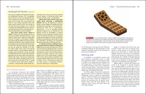
Figure 7-10 A user coordinate system is used to establish a drawing plane in 3D space so<br />
that objects can be drawn on the surface of the plane. The XYZ coordinate axes identify the<br />
orientation of the drawing plane. In this 3D model, the XY drawing plane is oriented so that<br />
objects can be added to the top surface of the part. Note the direction of the axes.<br />
Y<br />
Z<br />
X<br />
Snap is a function that allows the user<br />
to align (“snap”) the cursor to specifi c increments,<br />
or snap points, in an invisible grid.<br />
Snap can be used with or without the grid<br />
display turned on. However, it is common to<br />
set the snap spacing in conjunction with the<br />
grid spacing. For example, if the grid spacing<br />
is set to .50″, snap may be set to .25″ so that the<br />
cursor can be “snapped” to the grid points as<br />
well as the midpoints between grid lines.<br />
Object snap is a function that allows the<br />
cursor to be “snapped” to specifi c locations<br />
on an existing object. It can be set to one or<br />
more modes that determine the type of location.<br />
This is useful for drawing objects using<br />
points on an existing object, or entity, such as a<br />
line or circle. For example, the Endpoint object<br />
snap mode allows you to snap the cursor to<br />
an endpoint of an object, such as a line. The<br />
Midpoint object snap mode is used to snap the<br />
cursor to the midpoint of an object. The Center<br />
object snap mode is used to snap the cursor to<br />
the center of a circle or an arc. Object snap can<br />
also be used to draw objects that are parallel,<br />
perpendicular, or tangent to other objects.