
You also want an ePaper? Increase the reach of your titles
YUMPU automatically turns print PDFs into web optimized ePapers that Google loves.
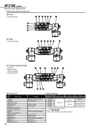
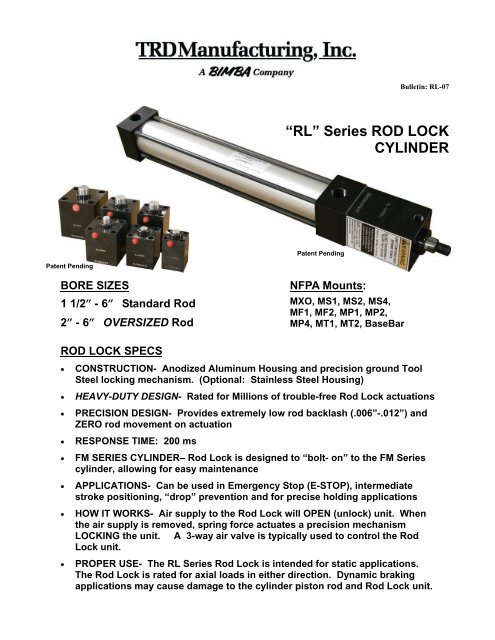
Patent Pending<br />
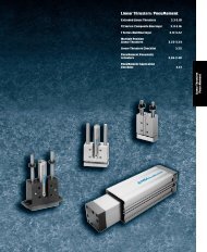
BORE SIZES<br />
1 1/2” - 6” Standard <strong>Rod</strong><br />
2” - 6” OVERSIZED <strong>Rod</strong><br />
ROD LOCK SPECS<br />
“RL” Series ROD LOCK<br />
CYLINDER<br />
• CONSTRUCTION- Anodized Aluminum Housing and precision ground Tool<br />
Steel locking mechanism. (Optional: Stainless Steel Housing)<br />
• HEAVY-DUTY DESIGN- Rated for Millions of trouble-free <strong>Rod</strong> <strong>Lock</strong> actuations<br />
• PRECISION DESIGN- Provides extremely low rod backlash (.006”-.012”) and<br />
ZERO rod movement on actuation<br />
• RESPONSE TIME: 200 ms<br />
Patent Pending<br />
NFPA Mounts:<br />
MXO, MS1, MS2, MS4,<br />
MF1, MF2, MP1, MP2,<br />
MP4, MT1, MT2, BaseBar<br />
• FM SERIES CYLINDER– <strong>Rod</strong> <strong>Lock</strong> is designed to “bolt- on” to the FM Series<br />
cylinder, allowing for easy maintenance<br />
• APPLICATIONS- Can be used in Emergency Stop (E-STOP), intermediate<br />
stroke positioning, “drop” prevention and for precise holding applications<br />
Bulletin: RL-07<br />
• HOW IT WORKS- Air supply to the <strong>Rod</strong> <strong>Lock</strong> will OPEN (unlock) unit. When<br />
the air supply is removed, spring force actuates a precision mechanism<br />
LOCKING the unit. A 3-way air valve is typically used to control the <strong>Rod</strong><br />
<strong>Lock</strong> unit.<br />
• PROPER USE- The RL Series <strong>Rod</strong> <strong>Lock</strong> is intended for static applications.<br />
The <strong>Rod</strong> <strong>Lock</strong> is rated for axial loads in either direction. Dynamic braking<br />
applications may cause damage to the cylinder piston rod and <strong>Rod</strong> <strong>Lock</strong> unit.
SERIES “RL” ROD LOCK<br />
-Construction<br />
1<br />
2<br />
3<br />
4<br />
5<br />
6<br />
13<br />
10<br />
LOCKING COLLAR- Hardened<br />
specialized tool steel, precision<br />
ground, multi-split collar design<br />
provides 4,000,000-5,000,000 cycles<br />
without fatigue or fracture<br />
PISTON-OUTER LOCK HOUSING<br />
Hardened tool steel, precision ground<br />
design also serves as a spring guide<br />
for uniform clamp force distribution<br />
with virtually no wear<br />
SPRING - Oversized for maximum<br />
power, heavy-duty coil spring (low<br />
fatigue) will provide millions of<br />
consistent rod lock actuations at full<br />
rated load<br />
BALL BEARINGS - Hardened,<br />
precision ground (high grade) steel<br />
ball bearings provide total transfer of<br />
spring force to locking collar<br />
ROD LOCK GUIDE (Steel) - Centers<br />
<strong>Rod</strong> <strong>Lock</strong> to cylinder rod bushing and<br />
maintains perfect alignment eliminating<br />
binding or rod scraping or reduced<br />
locking force due to misalignment<br />
PISTON GUIDE - Hardened and<br />
ground steel guide that centers the<br />
piston-outer lock housing and provides<br />
bearing surface for piston/spring<br />
assembly<br />
7<br />
8<br />
9<br />
10<br />
11<br />
12<br />
13<br />
5<br />
1<br />
ROD GUIDE BEARING -<br />
High-load wear strip (PTFE<br />
based), self lubricating<br />
PISTON SEAL - Heavy lip<br />
design Carboxilated Nitrile<br />
construction. Seal is pressure<br />
activated and wear compensating<br />
for extended life (self lubricating<br />
material)<br />
ROD WIPER - Urethane<br />
RETAINING RING (Steel) -<br />
Retains coil spring compression<br />
(under very high spring<br />
force) and internal lock components.<br />
(NOTE: Do not remove)<br />
HOUSING - Precision<br />
machined from 6061-T6 aluminum,<br />
black anodized for corrosion<br />
resistance<br />
SLEEVE NUT (Steel) -<br />
Provides (4) tapped holes for<br />
mounting unit or MF1 flange<br />
FM SERIES CYLINDER -<br />
Refer to TRD catalog pages<br />
19-30 for specifications and<br />
options<br />
14<br />
CYLINDER PISTON ROD<br />
3<br />
4<br />
2<br />
11<br />
8<br />
“100% FILL” Ball Bearing Design<br />
The cavity between the <strong>Lock</strong>ing<br />
Collar and Outer <strong>Lock</strong> Housing is<br />
100% filled with ball bearings,<br />
providing UNIFORM distribution of<br />
<strong>Lock</strong>ing (Clamp / Holding) Force<br />
“UNIFORM” FORCE<br />
LOCKING<br />
COLLAR<br />
BALL<br />
BEARINGS<br />
PISTON<br />
ROD<br />
DESIGN ADVANTAGES<br />
6<br />
9<br />
14<br />
12<br />
• LOW METAL FATIGUE On all<br />
clamping components<br />
• SUPERIOR LOCKING FORCES-<br />
HIGHEST LOCKING FORCES IN<br />
THE INDUSTRY<br />
• NON WEARING- Low component<br />
fatigue eliminates wear and extends<br />
life to 4,000,000-5,000,000 cycles at<br />
full rated load<br />
7
SERIES “RL” ROD LOCK<br />
The TRD difference<br />
TRD’s floating rod bushing design and RL Series <strong>Rod</strong> <strong>Lock</strong> =<br />
OPTIMIZED RESULTS and Superior Performance.<br />
For rod locks to achieve the rated holding force and maximum cycle life, good<br />
alignment must be maintained between the locking mechanism and cylinder<br />
rod. With TRD’s Floating <strong>Rod</strong> Bushing design and accurate rod lock alignment–<br />
superior performance and trouble-free operation are assured.<br />
Note– Faulty alignment will cause rod damage and may drastically reduce<br />
holding force.<br />
Operating Principle<br />
CLAMPED (<strong>Lock</strong>ed) CONDITION<br />
Air Pressure Exhausted<br />
Piston/Outer <strong>Lock</strong> Housing<br />
Ball Bearings<br />
<strong>Lock</strong>ing Collar<br />
UNCLAMPED CONDITION (Free Moving Piston <strong>Rod</strong>)<br />
When air pressure is applied to rod lock, the air pressure<br />
overcomes the spring force, moving Piston/<br />
Outer <strong>Lock</strong>ing Housing. This movement provides<br />
clearance in the tapered mechanism allowing the<br />
<strong>Lock</strong>ing Collar to relax and<br />
provide free rod movement.<br />
Air pressure moves piston,<br />
compressing spring, which<br />
eliminates locking force<br />
When air pressure is exhausted from rod lock,<br />
high spring force is applied to the piston/outer lock<br />
housing which utilizes an ultra-fine tapered wedge<br />
mechanism. Ball bearings transfer the spring<br />
force directly to the locking collar. The locking<br />
collar is designed to flex and securely grip the rod.<br />
Clamping action does not move or disturb the rod,<br />
maintaining rod position during actuation<br />
Spring Force is applied directly<br />
to locking mechanism, clamping<br />
piston rod<br />
60-150 PSI Air Pressure
How to order: CYLINDER WITH ROD LOCK<br />
SERIES<br />
FM - MS4 - 2 X 4 - RL - 063200 - ( )<br />
MOUNT<br />
BORE<br />
STROKE<br />
HOW TO ORDER ROD LOCK PRODUCTS<br />
Note: Refer to TRD catalog pages 19-30 for complete FM Series information and available options<br />
How to order: CYLINDER / ROD LOCK Replacement Parts<br />
REPLACEMENT CYLINDER: FM - MS4 - 2 X 4 - RL - (______)<br />
SERIES<br />
CYLINDER BORE SIZE<br />
CYLINDER ROD SIZE<br />
CYLINDER "READY" FOR ROD LOCK<br />
MOUNT<br />
BORE<br />
STROKE<br />
OPTIONS (IF ANY)<br />
NOTE: <strong>Cylinders</strong> will ship with standard rod end (KK1) and standard rod extention (RLC dimension)<br />
unless otherwised noted by customer. (Refer to <strong>Rod</strong> Extention page for more info.)<br />
REPLACEMENT ROD LOCK (WITH MOUNTING KIT): RL - 063200<br />
ROD LOCK MODEL NUMBER<br />
ROD LOCK ONLY (NO MOUNTING KIT): RL - 063200-1<br />
ROD LOCK MODEL NUMBER<br />
"-1" INDICATES NO MOUNTING KIT<br />
REPLACEMENT MOUNTING KIT: MK - 063200<br />
MOUNTING KIT<br />
ROD LOCK MODEL<br />
OPTIONS (IF ANY)<br />
Patent Pending<br />
CYLINDER "READY" FOR ROD LOCK<br />
Patent Pending<br />
Patent Pending
BORE<br />
ROD LOCK PARTS LIST<br />
RATED<br />
HOLDING<br />
ROD ROD LOCK MODEL FORCE* ROD LOCK (Only) MOUNTING<br />
DIA. (INCLUDES MOUNTING KIT) (POUNDS) (NO MOUNTING KIT) KIT<br />
1 1/2 5/8 RL-063150 200 RL-063150-1 MK-063150<br />
2<br />
5/8<br />
1<br />
RL-063200<br />
RL-100200<br />
400<br />
300<br />
RL-063200-1<br />
RL-100200-1<br />
MK-063200<br />
MK-100200<br />
2 1/2<br />
5/8<br />
1<br />
RL-063250<br />
RL-100250<br />
650<br />
450<br />
RL-063250-1<br />
RL-100250-1<br />
MK-063250<br />
MK-100250<br />
3 1/4<br />
1<br />
1 3/8<br />
RL-100325<br />
RL-138325<br />
950<br />
950<br />
RL-100325-1<br />
RL-138325-1<br />
MK-100325<br />
MK-138325<br />
4<br />
1<br />
1 3/8<br />
RL-100400<br />
RL-138400<br />
1550<br />
1550<br />
RL-100400-1<br />
RL-138400-1<br />
MK-100400<br />
MK-138400<br />
5<br />
1<br />
1 3/8<br />
RL-100500<br />
RL-138500<br />
2150<br />
1950<br />
RL-100500-1<br />
RL-138500-1<br />
MK-100500<br />
MK-138500<br />
6<br />
1 3/8<br />
1 3/4<br />
RL-138600<br />
RL-175600<br />
2650<br />
2450<br />
RL-138600-1<br />
RL-175600-1<br />
MK-138600<br />
MK-175600<br />
NOTES:<br />
*HOLDING FORCE- Is the minumum rating over the entire life of the rod lock.<br />
Initial actual holding forces are higher.<br />
DO NOT disassemble <strong>Rod</strong> <strong>Lock</strong>- UNIT CONTAINS HIGH SPRING FORCE. Return to TRD Mfg. for service.<br />
Replacement <strong>Rod</strong> <strong>Lock</strong>s are shipped with a steel shaft. DO NOT remove 60-150 PSI supply air to <strong>Rod</strong> <strong>Lock</strong><br />
without steel shaft or cylinder rod in place- permanent damage to <strong>Rod</strong> <strong>Lock</strong> may occur.<br />
ROD LOCK WARRANTY- 12 Months from date of shipment<br />
Patent Pending
BORE<br />
ROD EXTENTION DATA<br />
FM CYLINDER WITH STANDARD ROD<br />
DIMENSIONS<br />
ROD ROD LOCK (Ref. Only) SLEEVE NUT<br />
DIA. MODEL RLC L C THREAD<br />
1 1/2 5/8 RL-063150 0.375 3.000 3.312 1/4-28 UNF<br />
2 5/8 RL-063200 0.375 3.000 3.312 5/16-24 UNF<br />
2 1/2 5/8 RL-063250 0.375 3.250 3.562 5/16-24 UNF<br />
3 1/4 1 RL-100325 0.500 4.000 4.313 3/8-24 UNF<br />
BORE<br />
4 1 RL-100400 0.500 4.000 4.313 3/8-24 UNF<br />
5 1 RL-100500 0.500 4.125 4.438 1/2-20 UNF<br />
6 1 3/8 RL-138600 0.625 4.500 4.813 1/2-20 UNF<br />
FM CYLINDER WITH OVERSIZED ROD<br />
DIMENSIONS<br />
ROD ROD LOCK (Ref. Only) SLEEVE NUT<br />
SLEEVE NUT<br />
THREAD<br />
SLEEVE NUT<br />
THREAD<br />
DIA. MODEL RLC L C THREAD FH<br />
2 1 RL-100200 0.500 3.750 4.000 5/16-24 UNF 0.375<br />
2 1/2 1 RL-100250 0.500 3.750 4.000 5/16-24 UNF 0.375<br />
3 1/4 1 3/8 RL-138325 0.625 4.000 4.500 3/8-24 UNF 0.625<br />
4 1 3/8 RL-138400 0.625 4.000 4.500 3/8-24 UNF 0.625<br />
5 1 3/8 RL-138500 0.625 4.125 4.625 1/2-20 UNF 0.625<br />
6 1 3/4 RL-175600 0.750 4.500 5.125 1/2-20 UNF 0.750<br />
HOW TO ORDER ROD EXTENTION NOTE<br />
The "C" dimension (without <strong>Rod</strong> <strong>Lock</strong> installed) is<br />
For a FM - MS4 - 2 X 4 - RL-063200 with 1" additional <strong>Rod</strong> with the "RL BUSHING" installed. "RL" Bushings<br />
Extention (RLC Dim.), the part number would be as follows: are diffferent than standard FM rod bushings.<br />
FM - MS4 - 2 X 4 - RL -063200- RLC = 1.375 The "C" dimension is shown for reference only.
ROD LOCK INSTALLATION INSTRUCTIONS<br />
1.) Apply constant air supply to <strong>Rod</strong> <strong>Lock</strong> port (60-150 PSI).<br />
2.) Remove shipping arbor from inside <strong>Rod</strong> <strong>Lock</strong>. Save for<br />
future use.<br />
3.) Remove excess grease and dirt form cylinder piston rod.<br />
Slide <strong>Rod</strong> <strong>Lock</strong> onto piston rod, using care not to damage<br />
seals or bearings.<br />
4.) Align <strong>Rod</strong> <strong>Lock</strong> to cylinder so that unit is square and flush.<br />
5.) Remove 60-150 PSI air supply to <strong>Rod</strong> <strong>Lock</strong>.<br />
6.) Fasten <strong>Rod</strong> <strong>Lock</strong> to cylinder using (4) Sleeve Nuts & <strong>Rod</strong>s.<br />
Tighten Sleeve Nuts a little at a time, in a clockwise<br />
rotation, finishing with the proper torque specification.<br />
7.) Cycle <strong>Rod</strong> <strong>Lock</strong> by applying 60-150 PSI to <strong>Rod</strong> <strong>Lock</strong> port,<br />
then removing 60-150 PSI pressure; cycle several times in<br />
this manner.<br />
8.) Apply constant 60-150 PSI air supply to <strong>Rod</strong> <strong>Lock</strong>, then<br />
hand-cycle the cylinder piston rod to check for proper<br />
alignment.<br />
9.) If cylinder piston rod does not move freely, remove <strong>Rod</strong><br />
<strong>Lock</strong> and repeat Installation Instructions. If the piston rod<br />
still “drags” or is difficult to move, check the squareness of<br />
the <strong>Rod</strong> <strong>Lock</strong> to the cylinder.<br />
WARNING– DO NOT DISASSEMBLE ROD LOCK -<br />
UNIT CONTAINS HIGH SPRING FORCE. Return to<br />
TRD Mfg. for service.<br />
CAUTION- DO NOT REMOVE 60-150 PSI AIR SUPPLY<br />
TO ROD LOCK UNIT WITHOUT SHIPPING ARBOR<br />
OR CYLINDER PISTON ROD IN PLACE– PERMANENT<br />
DAMAGE MAY OCCUR.<br />
Patent Pending<br />
SLEEVE NUT TORQUE SPECS<br />
BORE TORQUE (FT./LBS)<br />
1 1/2 5—7<br />
2 12—14<br />
2 1/2 12—14<br />
3 1/4 30<br />
4 35<br />
5 45<br />
6 50