Body Builders Info FUSO HD EURO V FPFVFSNZ PART 10.4 10.10 ...
Body Builders Info FUSO HD EURO V FPFVFSNZ PART 10.4 10.10 ...
Body Builders Info FUSO HD EURO V FPFVFSNZ PART 10.4 10.10 ...

Create successful ePaper yourself
Turn your PDF publications into a flip-book with our unique Google optimized e-Paper software.
<strong>Body</strong>/equipment mounting directives<br />
Australia/New Zealand
Inner title<br />
MITSUBISHI <strong>FUSO</strong> Service<br />
<strong>Body</strong>/equipment mounting directives<br />
FP.FV.FS<br />
Australia/New Zealand<br />
KAWASAKI, JAPAN
Contents<br />
1 Introduction<br />
1.1 The aim of these directives 5<br />
1.2 Symbols 7<br />
1.3 Vehicle safety 8<br />
1.4 Operational safety 9<br />
1.5 Accident prevention 10<br />
1.6 Note on copyright 11<br />
2 General<br />
2.1 Vehicle and model designations 12<br />
2.2 Technical advice and contact<br />
persons 14<br />
2.3 Product safety 15<br />
2.4 Ensuring traceability 17<br />
2.5 Mitsubishi three diamonds and<br />
Fuso emblem 18<br />
2.6 Trademarks 19<br />
2.7 Recycling of components 20<br />
2.8 Quality system 21<br />
3 Planning of bodies<br />
3.1 Selecting the chassis 22<br />
3.2 Vehicle modifications 24<br />
3.3 Dimensions, weights, vehicle overall<br />
height 25<br />
3.4 Vehicle type identification data 26<br />
3.5 Tires 27<br />
3.6 Bolted and welded connections 28<br />
3.7 Soundproofing 29<br />
3.8 Exhaust system 30<br />
3.9 Maintenance and repairs 31<br />
3.10 Optional equipment 34<br />
4 Technical threshold values for<br />
planning<br />
4.1 Vehicle overhang and technical<br />
wheelbases 35<br />
4.2 Weight distribution, CoG height,<br />
anti-roll bars 37<br />
4.3 Steerability 38<br />
i<br />
4.4 Clearance for basic vehicle and<br />
bodies 39<br />
4.5 Permissible load on cab roof 45<br />
4.6 Vehicle body incline 46<br />
4.7 Others 47<br />
5 Damage prevention<br />
5.1 Brake hoses/cables and lines 48<br />
5.2 Welding work 49<br />
5.3 Corrosion protection measures 51<br />
5.4 Bolted connections 54<br />
5.5 Painting work 60<br />
5.6 Chassis springs 73<br />
5.7 Tilting the cab 74<br />
5.8 Towing and tow-starting 75<br />
5.9 Risk of fire 76<br />
5.10 Electromagnetic compatibility (EMC) 77<br />
5.11 Storing and handing over the vehicle 78<br />
6 Modifications to the basic vehicle<br />
6.1 General 79<br />
6.2 Chassis frame material 81<br />
6.3 Drilling work on the vehicle frame 82<br />
6.4 Welding work on the vehicle frame 85<br />
6.5 Reinforcements 87<br />
6.6 Modifications to the wheelbase 89<br />
6.7 Frame modifications 90<br />
6.8 Mounting of implements and<br />
auxiliary components 94<br />
6.9 Cab 102<br />
6.10 Seats and seat belts 106<br />
6.11 Power take-offs 107<br />
6.12 Installation of propeller shafts 114<br />
6.13 Brake systems 115<br />
6.14 Exhaust system 128<br />
6.15 Fuel system 132<br />
6.16 Others 135<br />
7 Construction of bodies<br />
7.1 General 149<br />
7.2 Mounting frame 151<br />
7.3 Mounting frame attachment 155<br />
7.4 Others 159<br />
MITSUBISHI <strong>FUSO</strong> body/equipment mounting directives for FP.FV.FS Issue date: 16. 01. 2013<br />
! Only print out complete sections from the current version<br />
2
Contents<br />
8 Electrics/electronics<br />
8.1 Electrical system 172<br />
8.2 Electrical wiring 173<br />
8.3 Handling of electric/electronic<br />
equipment 180<br />
8.4 Power supply 181<br />
8.5 Charging/discharging balance 185<br />
8.6 Electric circuit continuity check 186<br />
8.7 Precautions for electric welding 188<br />
8.8 Locations and identification of<br />
various switches in cab 190<br />
8.9 Lighting 192<br />
8.10 Mobile communications systems 198<br />
8.11 Additional wiring for PTO 200<br />
8.12 Standard electric load limits on<br />
trailers 202<br />
8.13 Others 203<br />
9 Calculations<br />
9.1 Technical wheelbase 207<br />
9.2 Axle load calculation 208<br />
9.3 Connecting devices 216<br />
10 Technical data<br />
10.1 Model line-up 218<br />
10.2 Specifications 219<br />
10.3 Performance curve 225<br />
<strong>10.4</strong> Weight distribution table 274<br />
10.5 Chassis cab drawings 281<br />
10.6 Frame structure 309<br />
10.7 Spring characteristics 334<br />
10.8 Propeller shaft layout 338<br />
10.9 Power take-offs 341<br />
<strong>10.10</strong> Exhaust system layout 348<br />
10.11 Battery mounting layout 350<br />
10.12 Fuel tank mounting layout 354<br />
10.13 Brake systems 357<br />
10.14 Electrical systems 380<br />
10.15 Other equipment 475<br />
i<br />
MITSUBISHI <strong>FUSO</strong> body/equipment mounting directives for FP.FV.FS Issue date: 16. 01. 2013<br />
! Only print out complete sections from the current version<br />
3
1 Introduction<br />
MITSUBISHI <strong>FUSO</strong> TRUCK & BUS CORPORATION, as<br />
the manufacturer of MITSUBISHI <strong>FUSO</strong> vehicles,<br />
publishes this body/equipment mounting directive to<br />
provide body manufacturers with important technical<br />
information about the basic vehicle. This information<br />
must be observed by the body manufacturer in the<br />
production of bodies and equipment, fittings and<br />
modifications for MITSUBISHI <strong>FUSO</strong> vehicles.<br />
Due to the large number of body manufacturers and<br />
body types, MITSUBISHI <strong>FUSO</strong> TRUCK & BUS CORPO-<br />
RATION cannot take into account all the possible<br />
modifications to the vehicle, e.g. performance,<br />
stability, load distribution, center of gravity and<br />
handling characteristics, that may result from the<br />
design of attachments, bodies, equipment or modifications.<br />
For this reason, MITSUBISHI <strong>FUSO</strong> TRUCK &<br />
BUS CORPORATION can accept no body manufacturer<br />
liability for accidents or injuries sustained as a result<br />
of such modifications to the vehicles if such modifications<br />
have a negative impact on the overall vehicle.<br />
Accordingly, MITSUBISHI <strong>FUSO</strong> TRUCK & BUS<br />
CORPORATION will only assume liability as vehicle<br />
manufacturer within the scope of the design, production<br />
and instruction services which it has performed<br />
itself.<br />
i<br />
The body manufacturer is bound to ensure that its<br />
bodies and equipment, fittings and modifications are<br />
themselves not defective, nor capable of causing<br />
defects or hazards to the overall vehicle. If this obligation<br />
is violated in any way, the body manufacturer shall<br />
assume full product liability. The body/equipment<br />
mounting directives enable MITSUBISHI <strong>FUSO</strong> TRUCK<br />
& BUS CORPORATION to instruct the body manufacturer<br />
about important aspects that must be observed<br />
when mounting its bodies and equipment, fittings and<br />
modifications.<br />
These body/equipment mounting directives are<br />
primarily intended for the professional manufacturers<br />
of bodies, equipment, fittings and modifications for<br />
our vehicles. As a result, these body/equipment<br />
mounting directives assume that the body manufacturer<br />
has suitable background knowledge. If you intend<br />
to mount attachments, bodies and equipment on or<br />
carry out modifications to our vehicles, please be<br />
aware that certain types of work (e.g. welding work on<br />
load-bearing components) may only be carried out by<br />
qualified personnel. This will avoid the risk of injury<br />
while also ensuring that the degree of quality required<br />
for the attachments, bodies, equipment and modifications<br />
is given.<br />
MITSUBISHI <strong>FUSO</strong> body/equipment mounting directives for FP.FV.FS Issue date: 16. 01. 2013<br />
! Only print out complete sections from the current version<br />
4
1 Introduction<br />
1.1 The aim of these directives<br />
These directives serve as instructions for the manufacture<br />
of attachments, bodies, equipment and modification<br />
to other make bodies and major assemblies.<br />
These directives are divided into 10 interlinked chapters<br />
to help you find the information you require more<br />
quickly:<br />
1 Introduction ( page 4)<br />
2 General ( page 12)<br />
3 Planning of bodies ( page 22)<br />
4 Technical threshold values for planning<br />
( page 35)<br />
5 Damage prevention ( page 48)<br />
6 Modifications to the basic vehicle ( page 79)<br />
7 Construction of bodies ( page 149)<br />
8 Electrics/electronics ( page 172)<br />
9 Calculations ( page 207)<br />
10 Technical data ( page 218)<br />
Appendix<br />
Index ( page 484)<br />
i<br />
1.1 The aim of these directives<br />
i Additional information<br />
The index, in PDF format, is linked to help you find<br />
the information you require quickly.<br />
Make absolutely sure that you observe the technical<br />
threshold values selected in Section 4 "Technica<br />
l threshold values for planning" ( page 35) as<br />
planning must be based on these values.<br />
Section 6 "Modifications to the basic vehicle"<br />
( page 79) and Section 7 "Construction of<br />
bodies" ( page 149) represent the main source of<br />
technical information contained in these body/<br />
equipment mounting directives.<br />
MITSUBISHI <strong>FUSO</strong> body/equipment mounting directives for FP.FV.FS Issue date: 16. 01. 2013<br />
! Only print out complete sections from the current version<br />
5
1 Introduction<br />
a Risk of accident<br />
Before installing any attachments, special-purpose<br />
bodies, equipment or carrying out any modifications<br />
to the basic vehicle and/or its assemblies,<br />
you must read the relevant sections of the Instruction<br />
Manual, as well as the operating and assembly<br />
instructions issued by the manufacturer of the<br />
accessories and items of optional equipment.<br />
You could otherwise fail to recognize dangers,<br />
which could result in injury to yourself or others.<br />
The illustrations below explain the difference between<br />
"Basic vehicle" and "<strong>Body</strong>":<br />
Basic vehicle<br />
<strong>Body</strong><br />
i<br />
1.1 The aim of these directives<br />
The instructions listed herein must be observed in full<br />
to maintain the operational reliability and road safety<br />
of the chassis and for observance of material defect<br />
claims.<br />
Illustrations and schematic drawings are examples<br />
only and serve to explain the texts and tables.<br />
References to regulations, standards, directives etc.<br />
are given in keywords and serve for information only.<br />
Additional information is available from any<br />
MITSUBISHI <strong>FUSO</strong> Service Center<br />
Your<br />
MITSUBISHI <strong>FUSO</strong> TRUCK & BUS CORPORATION<br />
MITSUBISHI <strong>FUSO</strong> body/equipment mounting directives for FP.FV.FS Issue date: 16. 01. 2013<br />
! Only print out complete sections from the current version<br />
6
1 Introduction<br />
1.2 Symbols<br />
The following symbols are used in these directives:<br />
a Risk of accident<br />
A warning draws your attention to possible risks of<br />
accident and injury to yourself and others.<br />
H Environmental note<br />
An environmental note gives you tips on the protection<br />
of the environment.<br />
! Property damage<br />
This note draws your attention to possible damage<br />
to your vehicle.<br />
i Additional information<br />
This note points out any additional information.<br />
page<br />
This symbol indicates the page on which you will find<br />
further information on the subject. These pages are<br />
cross-linked in the PDF file.<br />
i<br />
1.2 Symbols<br />
MITSUBISHI <strong>FUSO</strong> body/equipment mounting directives for FP.FV.FS Issue date: 16. 01. 2013<br />
! Only print out complete sections from the current version<br />
7
1 Introduction<br />
1.3 Vehicle safety<br />
a Risk of accident and injury<br />
The use of parts, assemblies or conversion parts<br />
and accessories which have not been approved<br />
may jeopardize the safety of the vehicle.<br />
Before installing any attachments, special-purpose<br />
bodies, equipment or carrying out any modifications<br />
to the basic vehicle and/or its assemblies,<br />
you must read the relevant sections of the Instruction<br />
Manual, as well as the operating and assembly<br />
instructions issued by the manufacturer of the<br />
accessories and items of optional equipment.<br />
You could otherwise fail to recognize dangers,<br />
which could result in injury to yourself or others.<br />
Official acceptance by public testing bodies or<br />
official approval does not rule out safety hazards.<br />
Notes on vehicle safety<br />
MITSUBISHI <strong>FUSO</strong> recommends<br />
using appropriate parts only for each particular vehicle<br />
model.<br />
i<br />
1.3 Vehicle safety<br />
In many countries, parts that make extensive changes<br />
to the vehicle can invalidate the general operating<br />
permit. Specifically, this concerns parts which:<br />
• change the vehicle type approved in the general<br />
operating permit<br />
• could endanger road users<br />
• could adversely affect exhaust emissions or noise<br />
levels<br />
i Additional information<br />
Make absolutely sure that you comply with national<br />
registration regulations as attachments, bodies,<br />
equipment on or modifications to the vehicle will<br />
change the vehicle type approved and may<br />
invalidate the general operating permit.<br />
MITSUBISHI <strong>FUSO</strong> body/equipment mounting directives for FP.FV.FS Issue date: 16. 01. 2013<br />
! Only print out complete sections from the current version<br />
8
1 Introduction<br />
1.4 Operational safety<br />
a Risk of accident<br />
Before installing any attachments, special-purpose<br />
bodies, equipment or carrying out any modifications<br />
to the basic vehicle and/or its assemblies,<br />
you must read the relevant sections of the Instruction<br />
Manual, as well as the operating and assembly<br />
instructions issued by the manufacturer of the<br />
accessories and items of optional equipment.<br />
You could otherwise fail to recognize dangers,<br />
which could result in injury to yourself or others.<br />
Work incorrectly carried out on electronic components<br />
and their software could prevent this equipment<br />
from working correctly. Since the electronic<br />
systems are networked, this might also affect<br />
systems that have not been modified.<br />
Malfunctions in the electronic systems could seriously<br />
jeopardize the operating safety of the vehicle.<br />
i<br />
1.4 Operational safety<br />
MITSUBISHI <strong>FUSO</strong> body/equipment mounting directives for FP.FV.FS Issue date: 16. 01. 2013<br />
! Only print out complete sections from the current version<br />
9
1 Introduction<br />
1.5 Accident prevention<br />
Observe the requirements and precautions set out in<br />
this manual when carrying out body-building work or<br />
modification work.<br />
The body, the attached or installed equipment and any<br />
modifications must comply with the applicable laws<br />
and ordinances as well as work safety or accident<br />
prevention regulations, safety rules and accident<br />
insurer requirements.<br />
All technical means shall be used to avoid operating<br />
conditions that may be unsafe or liable to cause an<br />
accident.<br />
All national laws, directives and registration<br />
requirements must be complied with.<br />
The manufacturer of the attachment, body, equipment<br />
or conversion or the device manufacturer is<br />
responsible for compliance with these laws and<br />
regulations.<br />
i<br />
1.5 Accident prevention<br />
MITSUBISHI <strong>FUSO</strong> body/equipment mounting directives for FP.FV.FS Issue date: 16. 01. 2013<br />
! Only print out complete sections from the current version<br />
10
1 Introduction<br />
1.6 Note on copyright<br />
All the text, illustrations and data contained in these<br />
body/equipment mounting directives are protected<br />
by copyright.<br />
This also applies for the editions on CD-ROM, DVD or<br />
other media.<br />
If you have any questions, please contact the department<br />
responsible page 14.<br />
i<br />
1.6 Note on copyright<br />
MITSUBISHI <strong>FUSO</strong> body/equipment mounting directives for FP.FV.FS Issue date: 16. 01. 2013<br />
! Only print out complete sections from the current version<br />
11
2 General<br />
2.1 Vehicle and model designations<br />
2.1.1 Model coding system<br />
<br />
i<br />
FP54SGR3VFAA<br />
Cab style<br />
2.1 Vehicle and model designations<br />
Max.G.V.W & Drive system<br />
Development sequential number<br />
Suspension type<br />
Engine type<br />
Export specification<br />
Export specification<br />
AMT or Not<br />
Engine type<br />
Chassis arrangement for use<br />
Wheelbase (m)<br />
F: Forward cab<br />
P: 4 × 2<br />
S: 8 × 4<br />
V: 6 × 4<br />
1: Standard suspension<br />
2: New front two-axle<br />
4: Rear air suspension<br />
S: OM457<br />
Generation<br />
FA: Australia, New Zealand<br />
DE: Singapore, Hong Kong<br />
DU: China<br />
DB: Taiwan<br />
V: AMT<br />
2: 265 kW (360PS)/1,900 rpm<br />
3: 295 kW (401PS)/1,900 rpm<br />
5: 335 kW (455PS)/1,900 rpm<br />
D: for Dump (Tipper)<br />
M: for Concrete mixer<br />
R: for Semi trailer tractor<br />
K: for Outrigger equiped<br />
D: 2.89 to 3.20<br />
G: 3.80 to 4.10<br />
H: 4.10 to 4.40<br />
J: 4.40 to 4.70<br />
K: 4.70 to 5.00<br />
P: 5.90 to 6.20<br />
S: 6.50 to 6.80<br />
T: 9.80 to 7.10<br />
MITSUBISHI <strong>FUSO</strong> body/equipment mounting directives for FP.FV.FS Issue date: 16. 01. 2013<br />
! Only print out complete sections from the current version<br />
D<br />
C<br />
D<br />
12
C<br />
2 General<br />
<br />
i<br />
FV51J JD3LNRA<br />
Cab Style<br />
Drive system<br />
Development Order<br />
Suspension Type<br />
Engine Type<br />
2.1 Vehicle and model designations<br />
F: Forward cab<br />
1: Leaf suspension (full air brake)<br />
J: 6M70T3, 6M70T4<br />
Export specification Generation<br />
Code Destination<br />
Steering Wheel Location<br />
Engine Type<br />
Chassis arrangement for use<br />
Wheelbase (m)<br />
P: 4 × 2, GVM <strong>10.4</strong> to 13.5 tons<br />
V: 6 × 4, GVM 15.0 to 16.0 tons<br />
NR: Ecuador<br />
NF: Peru<br />
L: Left hand<br />
R: Right hand<br />
6M70 Model<br />
3: 279 kW (380PS)/2,000 rpm<br />
4: 309 kW (420PS)/2,000 rpm<br />
D: For Dump (Tipper)<br />
R: For Semi trailer tractor<br />
G: 3.80 to 4.10<br />
J: 4.40 to 4.70<br />
P: 5.90 to 6.20<br />
MITSUBISHI <strong>FUSO</strong> body/equipment mounting directives for FP.FV.FS Issue date: 16. 01. 2013<br />
! Only print out complete sections from the current version<br />
D<br />
D<br />
13
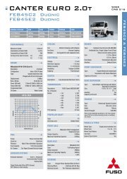
<strong>FUSO</strong> Model LOCAL Model GCW<br />
FP54SGR3VFAA FP410G1 4x2 40.0<br />
FV51SK3VFAA<br />
FV51SK5VFAA<br />
FS52SS5VFAA<br />
FS52SS5VFAB<br />
FV54SJR5VFAB<br />
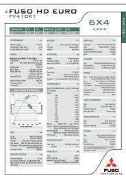
FV410K1 6x4<br />
FV470K1 6x4<br />
FS470S1<br />
8x4<br />
FS470S2<br />
8x4<br />
FV470J1<br />
6x4 Tractor<br />
50<br />
53<br />
60<br />
Engine<br />
OM457 Gross<br />
OM457 12L<br />
413PS/2031Nm<br />
(1495lbft)<br />
OM457 12L<br />
470PS/ 2227Nm<br />
(1644lbft)<br />
<strong>FUSO</strong> <strong>HD</strong> <strong>EURO</strong> 5<br />
T/M Wheels Diff / tyres Diff Options Wheelbas<br />
e mm<br />
G230-<br />
12sp AMT<br />
G330-12<br />
AMT<br />
Steel<br />
Steel<br />
Alloy<br />
Comments<br />
4.222 / 275/70 - 3800 A/SUS<br />
4.625 +<br />
11R22.5<br />
5.142 + 11R22.5<br />
4.222 + 275/70<br />
4.222 + 275/70<br />
5.142 + 11R22.5<br />
- 4300<br />
4300<br />
5870<br />
5870<br />
4.222 + 275/70 - 3860<br />
HIGH<br />
ROOF<br />
HIGH<br />
ROOF +
10 Technical data<br />
<strong>10.4</strong> Weight distribution table<br />
<strong>10.4</strong>.1 Weight distribution table<br />
<br />
Model FP54SGR3VFAA<br />
Technical wheelbase (m) 3.800<br />
Weight (kg)/From front<br />
Parts name<br />
axle center to center of<br />
gravity (m)<br />
Front bumber 99.7 / -1.220<br />
Steering system 97.2 / -0.760<br />
Cooling 120.0 / -0.920<br />
Step 34.4 / -0.820<br />
Engine control system 13.5 / 0.325<br />
Front suspension 20.5 / 0.000<br />
Front stabilizer 40.6 / -0.568<br />
Cab assembly 739.4 / -0.519<br />
Front cab mounting 90.5 / -1.215<br />
Rear cab mounting 69.3 / 0.690<br />
Engine (front) 819.7 / -0.276<br />
Engine (rear) 777.6 / 0.842<br />
Air intake system 33.7 / 0.250<br />
Pipe, electric system 81.3 / 0.539<br />
Enclosure 20.6 / 0.054<br />
Brake system 24.7 / 1.969<br />
Air tank 55.2 / 2.200<br />
Battery 100.5 / 1.436<br />
Exhaust system 202.4 / 1.238<br />
Propeller shaft assembly 0.9 / 2.558<br />
Fuel tank 394.0 / 2.026<br />
SCR system 85.1 / 1.000<br />
SCR air tank 1.0 / 2.000<br />
Frame and others 559.0 / 1.770<br />
Rear suspension 219.1 / 3.613<br />
Rear stabilizer 0.0 / 3.613<br />
Air suspension air tank 2.2 / 1.473<br />
Rear bumper 0.0 / 0.000<br />
Air conditioner unit 15.7 / -1.750<br />
Power take-off 0.0 / 0.000<br />
Transmission oil cooler 10.1 / 0.000<br />
INOMAT system 4.2 / 0.000<br />
Spare tire carrier 0.0 / 0.000<br />
Moment (kgf·m N·m) 2893.0 28380.0<br />
Sprung weight (kg) Front 3827<br />
Rear 905<br />
Total 4732<br />
Unsprung weight (kg) Front 742<br />
Rear 1117<br />
Total 1859<br />
Chassis cab weight (kg) Front 4569<br />
Rear 2022<br />
Total 6591<br />
CoG height (m) (kerb weight) 0.885<br />
i<br />
<strong>10.4</strong> Weight distribution table<br />
MITSUBISHI <strong>FUSO</strong> body/equipment mounting directives for FP.FV.FS Issue date: 16. 01. 2013<br />
! Only print out complete sections from the current version<br />
274
10 Technical data<br />
<br />
i<br />
<strong>10.4</strong> Weight distribution table<br />
Model FV51SK3VFAA FV51SK5VFAA FV51SK2VFAA<br />
Technical wheelbase (m) 4.300 4.300 4.300<br />
Weight (kg)/From front Weight (kg)/From front Weight (kg)/From front<br />
Parts name<br />
axle center to center of axle center to center of axle center to center of<br />
gravity (m)<br />
gravity (m)<br />
gravity (m)<br />
Front bumber 99.7 / -1.220 99.7 / -1.220 99.7 / -1.220<br />
Steering system 97.2 / -0.760 97.2 / -0.760 97.2 / -0.760<br />
Cooling 120.0 / -0.920 120.0 / -0.920 120.0 / -0.920<br />
Step 34.4 / -0.820 34.4 / -0.820 34.4 / -0.820<br />
Engine control system 23.1 / -0.030 23.1 / -0.030 23.1 / -0.030<br />
Front suspension 20.1 / 0.000 20.1 / 0.000 20.1 / 0.000<br />
Front stabilizer 0.0 / 0.000 0.0 / 0.000 0.0 / 0.000<br />
Cab assembly 747.4 / -0.519 747.4 / -0.519 747.4 / -0.519<br />
Front cab mounting 90.5 / -1.215 90.5 / -1.215 90.5 / -1.215<br />
Rear cab mounting 69.3 / 0.690 69.3 / 0.690 69.3 / 0.690<br />
Engine (front) 820.0 / -0.276 806.8 / -0.276 820.0 / -0.276<br />
Engine (rear) 777.6 / 0.842 790.8 / 0.842 777.6 / 0.842<br />
Air intake system 33.7 / 0.250 33.7 / 0.250 33.7 / 0.250<br />
Pipe,electric system 89.3 / 0.850 89.3 / 0.850 89.3 / 0.850<br />
Enclosure 20.6 / 0.054 20.6 / 0.054 20.6 / 0.054<br />
Brake system 24.7 / 1.783 24.7 / 1.783 24.7 / 1.783<br />
Air tank 21.3 / 1.783 21.3 / 1.783 21.3 / 1.783<br />
Battery 103.5 / 1.783 110.1 / 1.783 103.5 / 1.783<br />
Exhaust system 202.8 / 1.238 202.8 / 1.238 202.8 / 1.238<br />
Propeller shaft assembly 24.0 / 2.278 24.0 / 2.278 24.0 / 2.278<br />
Fuel tank 391.1 / 2.209 391.1 / 2.209 391.1 / 2.209<br />
SCR system 85.1 / 1.000 85.1 / 1.000 85.1 / 1.000<br />
SCR air tank 0.9 / 2.000 0.9 / 2.000 0.9 / 2.000<br />
Frame and others 816.3 / 2.864 816.3 / 2.864 816.3 / 2.864<br />
Rear suspension 570.2 / 4.303 570.2 / 4.303 570.2 / 4.303<br />
Rear stabilizer 0.0 / 0.000 0.0 / 0.000 0.0 / 0.000<br />
Air suspension air tank 0.0 / 0.000 0.0 / 0.000 0.0 / 0.000<br />
Rear bumper 0.0 / 0.000 0.0 / 0.000 0.0 / 0.000<br />
Air conditioner unit 15.7 / -0.750 15.7 / -0.750 15.7 / -0.750<br />
Power take-off 0.0 / 0.000 0.0 / 0.000 0.0 / 0.000<br />
Transmission oil cooler 10.1 / 0.000 10.1 / 0.000 10.1 / 0.000<br />
INOMAT system 4.2 / 0.000 4.2 / 0.000 4.2 / 0.000<br />
Spare tire carrier 0.0 / 0.000 0.0 / 0.000 0.0 / 0.000<br />
Moment (kgf·m N·m) 6031.8 59172.0 6058.4 59432.6 6031.9 59172.7<br />
Sprung weight (kg) Front 3945 3655 3903<br />
Rear 1st 684 832 705<br />
2nd 684 832 705<br />
Total 5313 5319 5313<br />
Unsprung weight (kg) Front 705 727 705<br />
Rear 1st 1075 1115 1073<br />
2nd 998 1038 996<br />
Total 2778 2880 2774<br />
Chassis cab weight (kg) Front 4650 4382 4608<br />
Rear 1st 1759 1947 1778<br />
2nd 1682 1870 1701<br />
Total 8091 8199 8087<br />
CoG height (m) (kerb weight) 0.825 0.825 0.825<br />
MITSUBISHI <strong>FUSO</strong> body/equipment mounting directives for FP.FV.FS Issue date: 16. 01. 2013<br />
! Only print out complete sections from the current version<br />
275
A<br />
10 Technical data<br />
i<br />
<strong>10.4</strong> Weight distribution table<br />
Model FV51SK2FAA FV54ST3VFAA FV54STK3VFAA<br />
Technical wheelbase (m) 4.300 6.380 6.380<br />
Weight (kg)/From front Weight (kg)/From front Weight (kg)/From front<br />
Parts name<br />
axle center to center of axle center to center of axle center to center of<br />
gravity (m)<br />
gravity (m)<br />
gravity (m)<br />
Front bumber 99.7 / -1.220 99.7 / -1.220 99.7 / -1.220<br />
Steering system 97.2 / -0.760 97.2 / -0.760 97.2 / -0.760<br />
Cooling 120.0 / -0.920 120.0 / -0.920 120.0 / -0.920<br />
Step 34.4 / -0.820 34.4 / -0.820 34.4 / -0.820<br />
Engine control system 31.4 / -0.030 23.5 / -0.030 23.5 / -0.030<br />
Front suspension 20.1 / 0.000 20.1 / 0.000 20.1 / 0.000<br />
Front stabilizer 0.0 / 0.000 0.0 / -0.568 0.0 / -0.568<br />
Cab assembly 746.1 / -0.519 744.8 / -0.519 744.8 / -0.519<br />
Front cab mounting 90.5 / -1.215 90.5 / -1.215 90.5 / -1.215<br />
Rear cab mounting 68.7 / 0.690 69.3 / 0.690 69.3 / 0.690<br />
Engine (front) 749.6 / -0.276 820.0 / -0.276 820.0 / -0.276<br />
Engine (rear) 1006.4 / 0.842 777.6 / 0.842 777.6 / 0.842<br />
Air intake system 35.6 / 0.250 33.7 / 0.250 33.7 / 0.250<br />
Pipe,electric system 87.9 / 0.850 92.2 / 0.850 92.2 / 0.850<br />
Enclosure 24.9 / 0.054 20.6 / 0.054 20.6 / 0.054<br />
Brake system 17.2 / 1.783 24.7 / 1.783 1.8 / 1.783<br />
Air tank 21.3 / 1.783 21.3 / 1.783 21.1 / 2.052<br />
Battery 110.1 / 1.783 103.5 / 1.783 105.0 / 1.783<br />
Exhaust system 202.8 / 1.238 202.8 / 1.238 231.7 / 2.288<br />
Propeller shaft assembly 100.2 / 2.278 153.9 / 4.220 157.0 / 4.22<br />
Fuel tank 388.7 / 2.209 391.1 / 2.208 391.1 / 3.896<br />
SCR system 86.7 / 1.000 85.1 / 1.000 85.1 / 2.707<br />
SCR air tank 1.8 / 2.000 0.9 / 2.000 0.9 / 2.000<br />
Frame and others 829.9 / 2.864 1057.5 / 3.832 1052.5 / 3.832<br />
Rear suspension 570.2 / 4.303 360.5 / 6.288 360.5 / 6.288<br />
Rear stabilizer 0.0 / 0.000 0.0 / 6.380 0.0 / 6.380<br />
Air suspension air tank 0.0 / 0.000 1.8 / 9.067 1.8 / 9.067<br />
Rear bumper 0.0 / 0.000 0.0 / 0.000 0.0 / 0.000<br />
Air conditioner unit 15.7 / -0.750 15.7 / -0.750 15.7 / -0.750<br />
Power take-off 0.0 / 0.000 0.0 / 0.000 0.0 / 0.000<br />
Transmission oil cooler 6.3 / 0.000 10.1 / 0.000 10.1 / 0.000<br />
INOMAT system 0.0 / 0.000 4.2 / 0.000 4.2 / 0.000<br />
Spare tire carrier 0.0 / 0.000 0.0 / 0.000 0.0 / 0.000<br />
Moment (kgf·m N·m) 6452.5 63298.7 8173.9 80186.0 9219.3 90441.5<br />
Sprung weight (kg) Front 4063 4341 4036<br />
Rear 1st 750 568 723<br />
2nd 750 568 723<br />
Total 5563 5477 5482<br />
Unsprung weight (kg) Front 717 704 731<br />
Rear 1st 976 1120 1047<br />
2nd 1084 1042 986<br />
Total 2777 2866 2764<br />
Chassis cab weight (kg) Front 4780 5045 4767<br />
Rear 1st 1726 1688 1770<br />
2nd 1835 1610 1709<br />
Total 8340 8343 8246<br />
CoG height (m) (kerb weight) 0.825 0.825 0.825<br />
MITSUBISHI <strong>FUSO</strong> body/equipment mounting directives for FP.FV.FS Issue date: 16. 01. 2013<br />
! Only print out complete sections from the current version<br />
E<br />
276
10 Technical data<br />
Model FV54SJR5VFAB FV54SJR5VFAA<br />
Technical wheelbase (m) 3.860 3.860<br />
Weight (kg)/From front Weight (kg)/From front<br />
Parts name<br />
axle center to center of axle center to center of<br />
gravity (m)<br />
gravity (m)<br />
Front bumber 99.7 / -1.220 99.7 / -1.220<br />
Steering system 97.2 / -0.760 97.2 / -0.760<br />
Cooling 120.0 / -0.920 120.0 / -0.920<br />
Step 34.4 / -0.820 34.4 / -0.820<br />
Engine control system 13.9 / -0.030 13.9 / -0.030<br />
Front suspension 20.1 / 0.000 20.1 / 0.000<br />
Front stabilizer 0.0 / -0.568 0.0 / -0.568<br />
Cab assembly 797.0 / -0.519 740.7 / -0.519<br />
Front cab mounting 90.5 / -1.215 90.5 / -1.215<br />
Rear cab mounting 69.3 / 0.690 69.3 / 0.690<br />
Engine (front) 780.3 / -0.276 784.7 / -0.276<br />
Engine (rear) 788.9 / 0.842 784.4 / 0.842<br />
Air intake system 35.8 / 0.250 33.7 / 0.250<br />
Pipe,electric system 82.9 / 0.920 82.9 / 0.920<br />
Enclosure 20.6 / 0.054 20.6 / 0.054<br />
Brake system 24.7 / 1.913 24.7 / 1.913<br />
Air tank 60.8 / 2.052 60.8 / 2.052<br />
Battery 99.6 / 1.436 99.6 / 1.436<br />
Exhaust system 202.4 / 1.238 202.4 / 1.238<br />
Propeller shaft assembly 38.4 / 2.081 38.4 / 2.081<br />
Fuel tank 403.0 / 1.998 403.0 / 1.998<br />
SCR system 85.1 / 1.000 85.1 / 1.000<br />
SCR air tank 1.1 / 2.052 1.1 / 2.052<br />
Frame and others 714.0 / 2.279 714.0 / 2.279<br />
Rear suspension 360.5 / 3.760 360.5 / 3.760<br />
Rear stabilizer 0.0 / 3.860 0.0 / 3.860<br />
Air suspension air tank 1.8 / 1.473 1.8 / 1.473<br />
Rear bumper 0.0 / 0.000 0.0 / 0.000<br />
Air conditioner unit 15.7 / -0.750 15.7 / -0.750<br />
Power take-off 0.0 / 0.000 0.0 / 0.000<br />
Transmission oil cooler 10.1 / 0.000 10.1 / 0.000<br />
INOMAT system 4.2 / 0.000 4.4 / 0.000<br />
Spare tire carrier 0.0 / 0.000 0.0 / 0.000<br />
Moment (kgf·m N·m) 4236.9 41563.6 4260.7 41797.2<br />
Sprung weight (kg) Front 3748 3642<br />
Rear 1st 662 686<br />
2nd 662 686<br />
Total 5072 5014<br />
Unsprung weight (kg) Front 724 723<br />
Rear 1st 1139 1138<br />
2nd 1067 1066<br />
Total 2930 2927<br />
Chassis cab weight (kg) Front 4472 4365<br />
Rear 1st 1801 1824<br />
2nd 1729 1752<br />
Total 8002 7941<br />
CoG height (m) (kerb weight) 0.825 0.825<br />
i<br />
<strong>10.4</strong> Weight distribution table<br />
MITSUBISHI <strong>FUSO</strong> body/equipment mounting directives for FP.FV.FS Issue date: 16. 01. 2013<br />
! Only print out complete sections from the current version<br />
277
10 Technical data<br />
<br />
i<br />
<strong>10.4</strong> Weight distribution table<br />
Model FS52SS3VFAA FS52SS5VFAA FS52SS5VFAB<br />
Technical wheelbase (m) 4.880 4.880 4.880<br />
Weight (kg)/From front Weight (kg)/From front Weight (kg)/From front<br />
Parts name<br />
axle center to center of axle center to center of axle center to center of<br />
gravity (m)<br />
gravity (m)<br />
gravity (m)<br />
Front bumber 99.8 / -2.150 99.8 / -2.150 99.8 / -2.150<br />
Steering system 157.1 / -1.180 157.1 / -1.180 157.1 / -1.180<br />
Cooling 120.0 / -1.850 120.0 / -1.850 120.0 / -1.850<br />
Step 35.0 / -1.750 35.0 / -1.750 35.0 / -1.750<br />
Engine control system 13.5 / -0.960 13.5 / -0.960 13.5 / -0.960<br />
Front suspension 66.9 / 0.000 66.9 / 0.000 66.9 / 0.000<br />
Front stabilizer 41.0 / -1.498 41.0 / -1.498 41.0 / -1.498<br />
Cab assembly 748.1 / -1.458 738.2 / -1.458 796.0 / -1.458<br />
Front cab mounting 90.1 / -2.145 90.1 / -2.145 90.1 / -2.145<br />
Rear cab mounting 69.3 / -0.240 69.3 / -0.240 69.3 / -0.240<br />
Engine (front) 800.7 / -1.281 805.7 / -1.281 814.6 / -1.281<br />
Engine (rear) 776.5 / -0.088 789.7 / -0.088 780.8 / -0.088<br />
Air intake system 33.7 / -0.680 33.7 / -0.680 35.8 / -0.680<br />
Pipe,electric system 99.0 / 0.020 99.0 / 0.020 99.0 / 0.020<br />
Enclosure 20.8 / -0.867 20.8 / -0.867 20.8 / -0.867<br />
Brake system 25.4 / 2.319 25.4 / 2.319 25.4 / 2.319<br />
Air tank 33.5 / 2.775 33.5 / 2.775 33.5 / 2.775<br />
Battery 99.2 / 2.775 99.2 / 2.775 99.2 / 2.775<br />
Exhaust system 222.6 / 2.251 222.6 / 2.251 222.6 / 2.251<br />
Propeller shaft assembly 26.7 / 2.542 26.7 / 2.542 26.7 / 2.542<br />
Fuel tank 453.4 / 3.050 453.4 / 3.050 453.4 / 3.050<br />
SCR system 84.6 / 0.967 84.6 / 0.967 84.6 / 0.967<br />
SCR air tank 2.8 / 2.775 2.8 / 2.775 2.8 / 2.775<br />
Frame and others 1042.0 / 2.808 1042.0 / 2.808 1042.0 / 2.808<br />
Rear suspension 570.2 / 4.880 570.2 / 4.880 537.0 / 4.880<br />
Rear stabilizer 0.0 / 0.000 0.0 / 0.000 0.0 / 0.000<br />
Air suspension air tank 0.0 / 0.000 0.0 / 0.000 0.0 / 0.000<br />
Rear bumper 18.0 / 8.535 18.0 / 8.535 18.0 / 8.535<br />
Air conditioner unit 15.0 / -1.680 0.0 / -1.680 0.0 / -1.680<br />
Power take-off 19.0 / 0.000 19.0 / 0.000 19.0 / 0.000<br />
Transmission oil cooler 11.0 / -0.930 11.0 / -0.930 11.0 / -0.930<br />
INOMAT system 4.2 / -0.930 4.2 / -0.930 4.2 / -0.930<br />
Spare tire carrier 20.0 / 7.033 20.0 / 7.033 20.0 / 7.033<br />
Moment (kgf·m N·m) 5241.1 51397.6 5221.4 51204.6 5014.7 49177.5<br />
Sprung weight (kg) Front 1st 2329 2340 2370<br />
2nd 2329 2340 2370<br />
Rear 1st 542 535 535<br />
2nd 542 535 535<br />
Total 5742 5750 5810<br />
Unsprung weight (kg) Front 1st 729 725 730<br />
2nd 729 725 730<br />
Rear 1st 1080 1040 1075<br />
2nd 1003 963 998<br />
Total 3541 3453 3533<br />
Chassis cab weight (kg) Front 1st 3058 3065 3100<br />
2nd 3058 3065 3100<br />
Rear 1st 1622 1575 1610<br />
2nd 1545 1498 1533<br />
Total 9283 9203 9343<br />
CoG height (m) (kerb weight) 0.790 0.790 0.790<br />
MITSUBISHI <strong>FUSO</strong> body/equipment mounting directives for FP.FV.FS Issue date: 16. 01. 2013<br />
! Only print out complete sections from the current version<br />
278
E<br />
10 Technical data<br />
Model FS52SS3FAA<br />
Technical wheelbase (m) 4.940<br />
Weight (kg)/From front<br />
Parts name<br />
axle center to center of<br />
gravity (m)<br />
Front bumber 99.7 / -2.150<br />
Steering system 157.1 / -1.180<br />
Cooling 120.0 / -1.850<br />
Step 35.0 / -1.750<br />
Engine control system 13.5 / -0.960<br />
Front suspension 66.9 / 0.000<br />
Front stabilizer 41.0 / -1.498<br />
Cab assembly 748.1 / -1.458<br />
Front cab mounting 90.1 / -2.145<br />
Rear cab mounting 69.3 / -0.240<br />
Engine (front) 800.7 / -1.281<br />
Engine (rear) 776.5 / -0.088<br />
Air intake system 33.7 / -0.680<br />
Pipe,electric system 99.0 / 0.020<br />
Enclosure 20.8 / -0.867<br />
Brake system 25.4 / 2.319<br />
Air tank 33.5 / 2.775<br />
Battery 99.2 / 2.775<br />
Exhaust system 222.6 / 2.251<br />
Propeller shaft assembly 26.7 / 2.542<br />
Fuel tank 453.4 / 3.050<br />
SCR system 84.6 / 1.897<br />
SCR air tank 2.8 / 2.775<br />
Frame and others 1032.9 / 2.808<br />
Rear suspension 570.2 / 4.880<br />
Rear stabilizer 0.0 / 0.000<br />
Air suspension air tank 0.0 / 0.000<br />
Rear bumper 18.0 / 8.535<br />
Air conditioner unit 15.0 / -1.680<br />
Power take-off 19.0 / 0.000<br />
Transmission oil cooler 11.0 / -0.930<br />
INOMAT system 4.2 / -0.930<br />
Spare tire carrier 20.0 / 7.033<br />
Moment (kgf·m N·m) 5294.5 51921.8<br />
Sprung weight (kg) Front 1st 2605<br />
2nd 2427<br />
Rear 1st 380<br />
2nd 398<br />
Total 5810<br />
Unsprung weight (kg) Front 1st 748<br />
2nd 749<br />
Rear 1st 1044<br />
2nd 967<br />
Total 3508<br />
Chassis cab weight (kg) Front 1st 3353<br />
2nd 3176<br />
Rear 1st 1424<br />
2nd 1365<br />
Total 9318<br />
CoG height (m) (kerb weight) 0.790<br />
i<br />
<strong>10.4</strong> Weight distribution table<br />
MITSUBISHI <strong>FUSO</strong> body/equipment mounting directives for FP.FV.FS Issue date: 16. 01. 2013<br />
! Only print out complete sections from the current version<br />
279
10 Technical data<br />
<strong>10.4</strong>.2 Option equipment<br />
Group OPT<br />
Note. *1 Distance from Fr. Axle Center ; +: backward, -: forward<br />
*2 G:3800/K:4900/T:7040/J:4520/S:6530<br />
i<br />
<strong>10.4</strong> Weight distribution table<br />
MASS [kg] MASS CENTER POSITION [m]*1<br />
FP-R FV FV-R FS FP-R FV FV-R FS<br />
Chassis LSD — 10 Same as W.B. length*2<br />
Flywheel PTO — 10 — 10 —<br />
11R22.5 — Fr: +4<br />
Re: -16<br />
275/70R22.5 Fr: - 9<br />
Re: +17<br />
Front under run protector<br />
less<br />
Front suspension<br />
Front equalizer less<br />
Front stabilizer<br />
— Fr: -65<br />
Re: -65<br />
— Fr: +7<br />
Re: +27<br />
Fr: - 5<br />
Re: +57<br />
— Fr: 0.000<br />
Re:<br />
(K) 4.300<br />
(T) 6.380<br />
Fr: 0.000<br />
Re: 3.800<br />
— Fr: 0.000<br />
Re: 3.860<br />
— Fr: 0.000<br />
Re: 5.870<br />
Fr: 0.000<br />
Re: 5.870<br />
MITSUBISHI <strong>FUSO</strong> body/equipment mounting directives for FP.FV.FS Issue date: 16. 01. 2013<br />
! Only print out complete sections from the current version<br />
Remark<br />
-36 -1.220 -1.220 -1.220 -2.150 NZ<br />
— — — +3 — — — — NZ<br />
NZ<br />
NZ<br />
280
A<br />
E<br />
E<br />
10 Technical data<br />
10.5 Chassis cab drawings<br />
10.5.1 Chassis cab drawings<br />
i<br />
Model Page Download<br />
FP54SGR3VFAA 282 .dxf<br />
FV51SK3VFAA 283 .dxf<br />
FV51SK5VFAA<br />
FV51SK2VFAA<br />
FV51SK2FAA 284 .dxf<br />
FV54ST3VFAA 285 .dxf<br />
FV54STK3VFAA 286 .dxf<br />
FV54SJR5VFAB 287 .dxf<br />
FV54SJR5VFAA 288 .dxf<br />
FS52SS3VFAA 289 .dxf<br />
FS52SS5VFAA<br />
FS52SS5VFAB 290 .dxf<br />
FS52SS3FAA 291 .dxf<br />
10.5 Chassis cab drawings<br />
MITSUBISHI <strong>FUSO</strong> body/equipment mounting directives for FP.FV.FS Issue date: 16. 01. 2013<br />
! Only print out complete sections from the current version<br />
281
10 Technical data<br />
FP54SGR3VFAA<br />
i<br />
10.5 Chassis cab drawings<br />
MITSUBISHI <strong>FUSO</strong> body/equipment mounting directives for FP.FV.FS Issue date: 16. 01. 2013<br />
! Only print out complete sections from the current version<br />
282
10 Technical data<br />
FV51SK3VFAA<br />
FV51SK5VFAA<br />
FV51SK2VFAA<br />
i<br />
10.5 Chassis cab drawings<br />
MITSUBISHI <strong>FUSO</strong> body/equipment mounting directives for FP.FV.FS Issue date: 16. 01. 2013<br />
! Only print out complete sections from the current version<br />
283
A<br />
10 Technical data<br />
FV51SK2FAA<br />
i<br />
10.5 Chassis cab drawings<br />
MITSUBISHI <strong>FUSO</strong> body/equipment mounting directives for FP.FV.FS Issue date: 16. 01. 2013<br />
! Only print out complete sections from the current version<br />
40<br />
284
10 Technical data<br />
FV54ST3VFAA<br />
i<br />
10.5 Chassis cab drawings<br />
MITSUBISHI <strong>FUSO</strong> body/equipment mounting directives for FP.FV.FS Issue date: 16. 01. 2013<br />
! Only print out complete sections from the current version<br />
285
E<br />
10 Technical data<br />
FV54STK3VFAA<br />
i<br />
10.5 Chassis cab drawings<br />
MITSUBISHI <strong>FUSO</strong> body/equipment mounting directives for FP.FV.FS Issue date: 16. 01. 2013<br />
! Only print out complete sections from the current version<br />
286
10 Technical data<br />
FV54SJR5VFAB<br />
i<br />
10.5 Chassis cab drawings<br />
MITSUBISHI <strong>FUSO</strong> body/equipment mounting directives for FP.FV.FS Issue date: 16. 01. 2013<br />
! Only print out complete sections from the current version<br />
287
10 Technical data<br />
FV54SJR5VFAA<br />
i<br />
10.5 Chassis cab drawings<br />
MITSUBISHI <strong>FUSO</strong> body/equipment mounting directives for FP.FV.FS Issue date: 16. 01. 2013<br />
! Only print out complete sections from the current version<br />
288
10 Technical data<br />
FS52SS3VFAA<br />
FS52SS5VFAA<br />
i<br />
10.5 Chassis cab drawings<br />
MITSUBISHI <strong>FUSO</strong> body/equipment mounting directives for FP.FV.FS Issue date: 16. 01. 2013<br />
! Only print out complete sections from the current version<br />
289
10 Technical data<br />
FS52SS5VFAB<br />
i<br />
10.5 Chassis cab drawings<br />
MITSUBISHI <strong>FUSO</strong> body/equipment mounting directives for FP.FV.FS Issue date: 16. 01. 2013<br />
! Only print out complete sections from the current version<br />
290
E<br />
10 Technical data<br />
FS52SS3FAA<br />
i<br />
10.5 Chassis cab drawings<br />
MITSUBISHI <strong>FUSO</strong> body/equipment mounting directives for FP.FV.FS Issue date: 16. 01. 2013<br />
! Only print out complete sections from the current version<br />
291
A<br />
E<br />
E<br />
10 Technical data<br />
10.5.2 Cab drawings<br />
i<br />
Model Page Download<br />
FP54SGR3VFAA 293 .dxf<br />
FV51SK3VFAA 294 .dxf<br />
FV51SK5VFAA<br />
FV51SK2VFAA<br />
FV51SK2FAA 295 .dxf<br />
FV54ST3VFAA 296 .dxf<br />
FV54STK3VFAA 297 .dxf<br />
FV54SJR5VFAB 298 .dxf<br />
FV54SJR5VFAA 299 .dxf<br />
FS52SS3VFAA 300 .dxf<br />
FS52SS5VFAA<br />
FS52SS5VFAB 301 .dxf<br />
FS52SS3FAA 302 .dxf<br />
10.5 Chassis cab drawings<br />
MITSUBISHI <strong>FUSO</strong> body/equipment mounting directives for FP.FV.FS Issue date: 16. 01. 2013<br />
! Only print out complete sections from the current version<br />
292
10 Technical data<br />
FP54SGR3VFAA<br />
i<br />
10.5 Chassis cab drawings<br />
MITSUBISHI <strong>FUSO</strong> body/equipment mounting directives for FP.FV.FS Issue date: 16. 01. 2013<br />
! Only print out complete sections from the current version<br />
293
10 Technical data<br />
FV51SK3VFAA<br />
FV51SK5VFAA<br />
FV51SK2VFAA<br />
i<br />
10.5 Chassis cab drawings<br />
MITSUBISHI <strong>FUSO</strong> body/equipment mounting directives for FP.FV.FS Issue date: 16. 01. 2013<br />
! Only print out complete sections from the current version<br />
294
A<br />
10 Technical data<br />
FV51SK2FAA<br />
i<br />
10.5 Chassis cab drawings<br />
MITSUBISHI <strong>FUSO</strong> body/equipment mounting directives for FP.FV.FS Issue date: 16. 01. 2013<br />
! Only print out complete sections from the current version<br />
295
10 Technical data<br />
FV54ST3VFAA<br />
i<br />
10.5 Chassis cab drawings<br />
MITSUBISHI <strong>FUSO</strong> body/equipment mounting directives for FP.FV.FS Issue date: 16. 01. 2013<br />
! Only print out complete sections from the current version<br />
296
E<br />
10 Technical data<br />
FV54STK3VFAA<br />
i<br />
10.5 Chassis cab drawings<br />
MITSUBISHI <strong>FUSO</strong> body/equipment mounting directives for FP.FV.FS Issue date: 16. 01. 2013<br />
! Only print out complete sections from the current version<br />
297
10 Technical data<br />
FV54SJR5VFAB<br />
i<br />
10.5 Chassis cab drawings<br />
MITSUBISHI <strong>FUSO</strong> body/equipment mounting directives for FP.FV.FS Issue date: 16. 01. 2013<br />
! Only print out complete sections from the current version<br />
298
10 Technical data<br />
FV54SJR5VFAA<br />
i<br />
10.5 Chassis cab drawings<br />
MITSUBISHI <strong>FUSO</strong> body/equipment mounting directives for FP.FV.FS Issue date: 16. 01. 2013<br />
! Only print out complete sections from the current version<br />
299
10 Technical data<br />
FS52SS3VFAA<br />
FS52SS5VFAA<br />
i<br />
10.5 Chassis cab drawings<br />
MITSUBISHI <strong>FUSO</strong> body/equipment mounting directives for FP.FV.FS Issue date: 16. 01. 2013<br />
! Only print out complete sections from the current version<br />
300
10 Technical data<br />
FS52SS5VFAB<br />
i<br />
10.5 Chassis cab drawings<br />
MITSUBISHI <strong>FUSO</strong> body/equipment mounting directives for FP.FV.FS Issue date: 16. 01. 2013<br />
! Only print out complete sections from the current version<br />
301
E<br />
10 Technical data<br />
FS52SS3FAA<br />
i<br />
10.5 Chassis cab drawings<br />
MITSUBISHI <strong>FUSO</strong> body/equipment mounting directives for FP.FV.FS Issue date: 16. 01. 2013<br />
! Only print out complete sections from the current version<br />
302
10 Technical data<br />
10.5.3 Reference drawing for building the front part of the rear body<br />
Motion of the cab and the snorkel<br />
i<br />
10.5 Chassis cab drawings<br />
MITSUBISHI <strong>FUSO</strong> body/equipment mounting directives for FP.FV.FS Issue date: 16. 01. 2013<br />
! Only print out complete sections from the current version<br />
303
10 Technical data<br />
Around the transmission<br />
FV5SVF (OM457+G230)<br />
i<br />
Chassis center<br />
Crankshaft center<br />
Inclination 103 /1000 5 53’<br />
90<br />
940<br />
205<br />
2090<br />
10.5 Chassis cab drawings<br />
MITSUBISHI <strong>FUSO</strong> body/equipment mounting directives for FP.FV.FS Issue date: 16. 01. 2013<br />
! Only print out complete sections from the current version<br />
Front axle center<br />
850<br />
883<br />
639<br />
50<br />
690 (Cab bridge center)<br />
999<br />
31<br />
420<br />
1975<br />
AdBlue fi tank<br />
3<br />
250<br />
322<br />
Muffler<br />
Back of flywheel housing<br />
221<br />
Battery box<br />
Charge hose<br />
Back of companion flange<br />
No.2 crossmember<br />
840<br />
Fuel hose<br />
Fuel tank<br />
300<br />
Top of frame<br />
Splash sheild rubber 50<br />
940 50<br />
448<br />
1490 448<br />
304
10 Technical data<br />
FS52SSVF (OM457+G230)<br />
i<br />
Chassis center<br />
Crankshaft center<br />
Inclination 103 /1000 5 53’<br />
90<br />
940<br />
205:Standard roof<br />
225:High roof<br />
2090:Standard roof<br />
2420:High roof<br />
10.5 Chassis cab drawings<br />
MITSUBISHI <strong>FUSO</strong> body/equipment mounting directives for FP.FV.FS Issue date: 16. 01. 2013<br />
! Only print out complete sections from the current version<br />
Front axle center<br />
850<br />
883<br />
639<br />
50<br />
690 (Cab bridge center)<br />
930<br />
31<br />
420<br />
2345<br />
250<br />
35<br />
322<br />
Back of flywheel housing<br />
221<br />
Front 2nd axle center<br />
Charge hose<br />
Back of companion flange<br />
Front exhaust pipe<br />
AdBlue fi tank<br />
No.2 crossmember<br />
300<br />
840<br />
Muffler<br />
Top of frame<br />
Splash shield rubber 50<br />
940 50<br />
448<br />
1490 448<br />
305
A<br />
10 Technical data<br />
FV51SK2FAA (OM457+Fuller)<br />
i<br />
Chassis center<br />
940<br />
205<br />
2090<br />
90<br />
Crankshaft center<br />
Inclination 103 /1000 5°53’<br />
Front axle center<br />
10.5 Chassis cab drawings<br />
850 250<br />
MITSUBISHI <strong>FUSO</strong> body/equipment mounting directives for FP.FV.FS Issue date: 16. 01. 2013<br />
! Only print out complete sections from the current version<br />
50<br />
883<br />
690 (Cab bridge center)<br />
639<br />
934<br />
68<br />
1975<br />
AdBlue tank<br />
Muffler<br />
Back of flywheel housing<br />
930<br />
68<br />
Back of companion flange<br />
Battery box<br />
Charge hose<br />
No.2 crossmember<br />
300<br />
840<br />
Fuel hose<br />
Fuel tank<br />
Top of frame<br />
Splash shield rubber<br />
Bridge center<br />
Engine rear cover<br />
448<br />
50<br />
Chassis center<br />
940 50<br />
1490<br />
685<br />
<br />
448<br />
833<br />
Front axle center<br />
306
10 Technical data<br />
i<br />
10.5 Chassis cab drawings<br />
10.5.4 Installation position of the rear body clamping U-bolt in the vicinity of the rear axle<br />
FV51S<br />
FS52S<br />
(Distance between tandems: 1320 mm)<br />
Avoid installing the rear body clamping U-bolt on these sections (for left and right sides).<br />
1350<br />
1060<br />
35<br />
Trunnion base center Trunnion crossmember center<br />
MITSUBISHI <strong>FUSO</strong> body/equipment mounting directives for FP.FV.FS Issue date: 16. 01. 2013<br />
! Only print out complete sections from the current version<br />
307
10 Technical data<br />
FV54S<br />
FV54SR<br />
i<br />
Avoid installing the rear body clamping U-bolt on these sections (for left and right sides).<br />
1600 1300<br />
140<br />
No.4 crossmember center Rear 2nd spring hanger center<br />
10.5 Chassis cab drawings<br />
MITSUBISHI <strong>FUSO</strong> body/equipment mounting directives for FP.FV.FS Issue date: 16. 01. 2013<br />
! Only print out complete sections from the current version<br />
308
10 Technical data<br />
10.6 Frame structure<br />
10.6.1 Details of crossmembers<br />
i<br />
Section Page Download<br />
A1, A2, A3, A4, A5, A6 310 .dxf<br />
B1, B2, B3 311 .dxf<br />
C1, C2, C3 312 .dxf<br />
D1, D2, D3 313 .dxf<br />
E<br />
F1, F2, F3 314 .dxf<br />
G1, G2 315 .dxf<br />
H1, H2, H3 316 .dxf<br />
I1, I2, I3<br />
J1, J2 317 .dxf<br />
K<br />
L1, L2 318 .dxf<br />
M, N 319 .dxf<br />
10.6 Frame structure<br />
MITSUBISHI <strong>FUSO</strong> body/equipment mounting directives for FP.FV.FS Issue date: 16. 01. 2013<br />
! Only print out complete sections from the current version<br />
309
10 Technical data<br />
i<br />
10.6 Frame structure<br />
MITSUBISHI <strong>FUSO</strong> body/equipment mounting directives for FP.FV.FS Issue date: 16. 01. 2013<br />
! Only print out complete sections from the current version<br />
310
10 Technical data<br />
i<br />
10.6 Frame structure<br />
MITSUBISHI <strong>FUSO</strong> body/equipment mounting directives for FP.FV.FS Issue date: 16. 01. 2013<br />
! Only print out complete sections from the current version<br />
311
10 Technical data<br />
i<br />
10.6 Frame structure<br />
MITSUBISHI <strong>FUSO</strong> body/equipment mounting directives for FP.FV.FS Issue date: 16. 01. 2013<br />
! Only print out complete sections from the current version<br />
312
10 Technical data<br />
i<br />
10.6 Frame structure<br />
MITSUBISHI <strong>FUSO</strong> body/equipment mounting directives for FP.FV.FS Issue date: 16. 01. 2013<br />
! Only print out complete sections from the current version<br />
313
10 Technical data<br />
i<br />
10.6 Frame structure<br />
MITSUBISHI <strong>FUSO</strong> body/equipment mounting directives for FP.FV.FS Issue date: 16. 01. 2013<br />
! Only print out complete sections from the current version<br />
314
10 Technical data<br />
i<br />
10.6 Frame structure<br />
MITSUBISHI <strong>FUSO</strong> body/equipment mounting directives for FP.FV.FS Issue date: 16. 01. 2013<br />
! Only print out complete sections from the current version<br />
315
10 Technical data<br />
i<br />
10.6 Frame structure<br />
MITSUBISHI <strong>FUSO</strong> body/equipment mounting directives for FP.FV.FS Issue date: 16. 01. 2013<br />
! Only print out complete sections from the current version<br />
316
10 Technical data<br />
i<br />
10.6 Frame structure<br />
MITSUBISHI <strong>FUSO</strong> body/equipment mounting directives for FP.FV.FS Issue date: 16. 01. 2013<br />
! Only print out complete sections from the current version<br />
317
10 Technical data<br />
i<br />
10.6 Frame structure<br />
MITSUBISHI <strong>FUSO</strong> body/equipment mounting directives for FP.FV.FS Issue date: 16. 01. 2013<br />
! Only print out complete sections from the current version<br />
318
10 Technical data<br />
i<br />
10.6 Frame structure<br />
MITSUBISHI <strong>FUSO</strong> body/equipment mounting directives for FP.FV.FS Issue date: 16. 01. 2013<br />
! Only print out complete sections from the current version<br />
319
A<br />
E<br />
E<br />
10 Technical data<br />
10.6.2 Frame section modulus<br />
i<br />
Model Page<br />
FP54SGR3VFAA 321<br />
FV51SK2VFAA 322<br />
FV51SK2FAA<br />
FV51SK3VFAA<br />
FV51SK5VFAA<br />
FV54ST3VFAA 323<br />
FV54STK3VFAA 324<br />
FV54SJR5VFAB 325<br />
FV54SJR5VFAA<br />
FS52SS3VFAA 326<br />
FS52SS5VFAA 327<br />
FS52SS5VFAB<br />
FS52SS3FAA 328<br />
10.6 Frame structure<br />
MITSUBISHI <strong>FUSO</strong> body/equipment mounting directives for FP.FV.FS Issue date: 16. 01. 2013<br />
! Only print out complete sections from the current version<br />
320
10 Technical data<br />
<br />
i<br />
10.6 Frame structure<br />
MITSUBISHI <strong>FUSO</strong> body/equipment mounting directives for FP.FV.FS Issue date: 16. 01. 2013<br />
! Only print out complete sections from the current version<br />
321
A<br />
10 Technical data<br />
<br />
i<br />
10.6 Frame structure<br />
MITSUBISHI <strong>FUSO</strong> body/equipment mounting directives for FP.FV.FS Issue date: 16. 01. 2013<br />
! Only print out complete sections from the current version<br />
322
10 Technical data<br />
<br />
i<br />
10.6 Frame structure<br />
MITSUBISHI <strong>FUSO</strong> body/equipment mounting directives for FP.FV.FS Issue date: 16. 01. 2013<br />
! Only print out complete sections from the current version<br />
323
E<br />
10 Technical data<br />
<br />
i<br />
<br />
<br />
<br />
<br />
<br />
<br />
<br />
<br />
<br />
<br />
<br />
<br />
<br />
10.6 Frame structure<br />
MITSUBISHI <strong>FUSO</strong> body/equipment mounting directives for FP.FV.FS Issue date: 16. 01. 2013<br />
! Only print out complete sections from the current version<br />
<br />
<br />
<br />
<br />
<br />
<br />
<br />
<br />
<br />
<br />
<br />
<br />
<br />
<br />
<br />
<br />
<br />
<br />
<br />
<br />
<br />
<br />
<br />
<br />
<br />
<br />
<br />
<br />
<br />
<br />
<br />
<br />
<br />
<br />
<br />
<br />
<br />
<br />
<br />
<br />
<br />
<br />
<br />
<br />
<br />
<br />
<br />
<br />
<br />
<br />
<br />
<br />
<br />
<br />
<br />
<br />
324
10 Technical data<br />
<br />
i<br />
10.6 Frame structure<br />
MITSUBISHI <strong>FUSO</strong> body/equipment mounting directives for FP.FV.FS Issue date: 16. 01. 2013<br />
! Only print out complete sections from the current version<br />
325
10 Technical data<br />
<br />
i<br />
10.6 Frame structure<br />
MITSUBISHI <strong>FUSO</strong> body/equipment mounting directives for FP.FV.FS Issue date: 16. 01. 2013<br />
! Only print out complete sections from the current version<br />
326
10 Technical data<br />
<br />
i<br />
10.6 Frame structure<br />
MITSUBISHI <strong>FUSO</strong> body/equipment mounting directives for FP.FV.FS Issue date: 16. 01. 2013<br />
! Only print out complete sections from the current version<br />
327
E<br />
10 Technical data<br />
<br />
i<br />
<br />
<br />
<br />
<br />
<br />
<br />
<br />
<br />
<br />
<br />
<br />
<br />
<br />
<br />
<br />
<br />
<br />
<br />
10.6 Frame structure<br />
MITSUBISHI <strong>FUSO</strong> body/equipment mounting directives for FP.FV.FS Issue date: 16. 01. 2013<br />
! Only print out complete sections from the current version<br />
<br />
<br />
<br />
<br />
<br />
<br />
<br />
<br />
<br />
<br />
<br />
<br />
<br />
<br />
<br />
<br />
<br />
<br />
<br />
<br />
<br />
<br />
<br />
<br />
<br />
<br />
<br />
<br />
<br />
<br />
<br />
<br />
<br />
<br />
<br />
<br />
<br />
<br />
<br />
<br />
<br />
<br />
<br />
<br />
<br />
<br />
<br />
<br />
<br />
<br />
<br />
<br />
<br />
<br />
<br />
<br />
<br />
<br />
<br />
<br />
<br />
<br />
<br />
328
A<br />
E<br />
E<br />
10 Technical data<br />
10.6.3 Positions of the bolts and rivets in the<br />
vicinity of the No. 2 cross member<br />
i<br />
Model Page Download<br />
FP54SGR3VFAA 330 .dxf<br />
FV51SK2VFAA 331 .dxf<br />
FV51SK2FAA<br />
FV51SK3VFAA<br />
FV51SK5VFAA<br />
FV54ST3VFAA<br />
FV54STK3VFAA<br />
FV54SJR5VFAA 332 .dxf<br />
FV54SJR5VFAB<br />
FS52SS3VFAA 333 .dxf<br />
FS52SS5VFAA<br />
FS52SS5VFAB<br />
FS52SS3FAA<br />
10.6 Frame structure<br />
MITSUBISHI <strong>FUSO</strong> body/equipment mounting directives for FP.FV.FS Issue date: 16. 01. 2013<br />
! Only print out complete sections from the current version<br />
329
10 Technical data<br />
<br />
i<br />
10.6 Frame structure<br />
MITSUBISHI <strong>FUSO</strong> body/equipment mounting directives for FP.FV.FS Issue date: 16. 01. 2013<br />
! Only print out complete sections from the current version<br />
330
A<br />
10 Technical data<br />
10.6 Frame structure<br />
<br />
i<br />
MITSUBISHI <strong>FUSO</strong> body/equipment mounting directives for FP.FV.FS Issue date: 16. 01. 2013<br />
! Only print out complete sections from the current version<br />
E<br />
331
10 Technical data<br />
<br />
i<br />
10.6 Frame structure<br />
MITSUBISHI <strong>FUSO</strong> body/equipment mounting directives for FP.FV.FS Issue date: 16. 01. 2013<br />
! Only print out complete sections from the current version<br />
332
10 Technical data<br />
<br />
i<br />
E<br />
10.6 Frame structure<br />
MITSUBISHI <strong>FUSO</strong> body/equipment mounting directives for FP.FV.FS Issue date: 16. 01. 2013<br />
! Only print out complete sections from the current version<br />
333
10 Technical data<br />
10.7 Spring characteristics<br />
10.7.1 Formulas of frame height<br />
Rear leaf suspension<br />
<br />
FV51SK<br />
<br />
FS52SS<br />
i<br />
Model<br />
STD<br />
OPT<br />
(New Zealand only)<br />
Model<br />
STD<br />
with equalizer<br />
OPT<br />
(New Zealand only)<br />
without equalizer<br />
OPT<br />
(New Zealand only)<br />
without equalizer<br />
Dimension (mm)<br />
Length×width×thickness<br />
- No.of leaves<br />
10.7 Spring characteristics<br />
Front Rear<br />
Spring rate<br />
N/mm<br />
{kgf/mm}<br />
Weight<br />
(kg/suspension)<br />
Dimension (mm)<br />
Length×width×thickness<br />
- No.of leaves<br />
Spring rate<br />
N/mm<br />
{kgf/mm}<br />
Tire Tire<br />
Formula of frame height Formula of frame height<br />
1500×90×23-3<br />
354<br />
{36.1}<br />
55 1320×90×30-5<br />
3059<br />
{311.9}<br />
295/80R22.5 11R22.5<br />
Hf = (1090 - 0.0189Wf) 10 Hr = (1068 - 0.00285Wr) 25<br />
1500×90×23-3<br />
354<br />
{36.1}<br />
55 1320×90×30-5<br />
3059<br />
{311.9}<br />
11R22.5 11R22.5<br />
Hf = (1088 - 0.0189Wf) 10 Hr = (1068 - 0.00285Wr) 25<br />
Dimension (mm)<br />
Length×width×thickness<br />
- No.of leaves<br />
Front Rear<br />
Spring rate<br />
N/mm<br />
{kgf/mm}<br />
Weight<br />
(kg/suspension)<br />
Dimension (mm)<br />
Length×width×thickness<br />
- No.of leaves<br />
Spring rate<br />
N/mm<br />
{kgf/mm}<br />
Tire Tire<br />
Formula of frame height Formula of frame height<br />
1500×90×23-3<br />
354<br />
{36.1}<br />
55 1320×90×30-5<br />
3059<br />
{311.9}<br />
295/80R22.5 11R22.5<br />
Hf = (1089 - 0.0095Wf) 10 Hr = (1068 - 0.00285Wr) 25<br />
1500×90×23-3<br />
354<br />
{36.1}<br />
55 1320×90×30-5<br />
3059<br />
{311.9}<br />
275/70R22.5 275/70R22.5<br />
Hff = (1046 - 0.0189Wff) 10 Hr = (1027 - 0.00285Wr) 25<br />
1500×90×23-3<br />
354<br />
{36.1}<br />
55 1320×90×30-5<br />
3059<br />
{311.9}<br />
11R22.5 11R22.5<br />
Hff = (1088 - 0.0189Wff) 10 Hr = (1068 - 0.00285Wr) 25<br />
MITSUBISHI <strong>FUSO</strong> body/equipment mounting directives for FP.FV.FS Issue date: 16. 01. 2013<br />
! Only print out complete sections from the current version<br />
Weight<br />
(kg/suspension)<br />
103<br />
103<br />
Weight<br />
(kg/suspension)<br />
103<br />
103<br />
103<br />
334
10 Technical data<br />
Rear air suspension<br />
<br />
FP54SGR<br />
<br />
FV54ST<br />
FV54SJR<br />
i<br />
Model<br />
STD<br />
OPT<br />
(New Zealand only)<br />
Model<br />
STD<br />
OPT<br />
(New Zealand only)<br />
STD<br />
OPT<br />
(New Zealand only)<br />
Dimension (mm)<br />
Length×width×thickness<br />
- No.of leaves<br />
10.7 Spring characteristics<br />
Front Rear<br />
Spring rate<br />
N/mm<br />
{kgf/mm}<br />
Weight<br />
(kg/suspension)<br />
Dimension (mm)<br />
Length×width×thickness - No.of leaves,<br />
Air spring effective diameter×height<br />
Tire Tire<br />
Formula of frame height Formula of frame height<br />
1650×90×16-4<br />
160<br />
{16.3}<br />
64 1095×90×35-2 φ300×h344<br />
295/80R22.5 11R22.5<br />
Hf = (1120 - 0.0357Wf) 10 Hr = (991 - 0.0025Wr) 25<br />
1650×90×16-4<br />
160<br />
{16.3}<br />
64 1095×90×35-2 φ300×h344<br />
Dimension (mm)<br />
Length×width×thickness<br />
- No.of leaves<br />
275/70R22.5 275/80R22.5<br />
Hf = (1077 - 0.0357Wf) 10 Hr = (950 - 0.0025Wr) 25<br />
Front Rear<br />
Spring rate<br />
N/mm<br />
{kgf/mm}<br />
Weight<br />
(kg/suspension)<br />
Dimension (mm)<br />
Length×width×thickness - No.of leaves,<br />
Air spring effective diameter×height<br />
Tire Tire<br />
Formula of frame height Formula of frame height<br />
1500×90×23-3<br />
354<br />
{36.1}<br />
55 995×80×35-2 φ250×h291<br />
295/80R22.5 11R22.5<br />
Hf = (1090 - 0.0189Wf) 10 Hrr = (1037 - 0.00125Wr) 25<br />
1500×90×23-3<br />
354<br />
{36.1}<br />
55 995×80×35-2 φ250×h291<br />
1500×90×23-3<br />
11R22.5 11R22.5<br />
Hf = (1088 - 0.0189Wf) 10 Hrr = (1037 - 0.00125Wr) 25<br />
354<br />
{36.1}<br />
55 995×80×35-2 φ250×h294<br />
295/80R22.5 11R22.5<br />
Hf = (1090 - 0.0189Wf) 10 Hrr = (1037 - 0.00125Wr) 25<br />
1500×90×23-3<br />
354<br />
{36.1}<br />
55 995×80×35-2 φ250×h294<br />
275/70R22.5 275/80R22.5<br />
Hf = (1046 - 0.0189Wf) 10 Hrr = (996 - 0.00125Wr) 25<br />
MITSUBISHI <strong>FUSO</strong> body/equipment mounting directives for FP.FV.FS Issue date: 16. 01. 2013<br />
! Only print out complete sections from the current version<br />
335
A<br />
10 Technical data<br />
10.7.2 Differential and tire bound height<br />
Rear axle<br />
<br />
i<br />
E<br />
C<br />
Model Tire<br />
FS52SS<br />
A B<br />
*: In case of aluminum wheel, D is 1870.<br />
<br />
*: In case of aluminum wheel, D is 1870.<br />
F<br />
D<br />
Wheel<br />
material<br />
10.7 Spring characteristics<br />
A B C D E F<br />
MITSUBISHI <strong>FUSO</strong> body/equipment mounting directives for FP.FV.FS Issue date: 16. 01. 2013<br />
! Only print out complete sections from the current version<br />
Overall<br />
width<br />
11R22.5 steel 33 196 809.5 1850* 330 1003 2459<br />
275/70R22.5 steel 33 147 808 1850* 330 1003 2456<br />
FV51SK 11R22.5 steel 33 196 809.5 1850 330 1003 2459<br />
E<br />
C<br />
Model Tire<br />
FP54SGR<br />
B<br />
A<br />
F<br />
D<br />
Wheel<br />
material<br />
A B C D E F<br />
Overall<br />
width<br />
11R22.5 steel 15 210 809.5 1850 330 1015 2459<br />
275/70R22.5 steel 15 160 808 1850 330 1015 2456<br />
FV54ST 11R22.5 steel 35 165 809.5 1850 330 1015 2459<br />
FV54SJR<br />
11R22.5 steel 20 165 809.5 1850* 330 1015 2459<br />
275/70R22.5 steel 20 115 808 1850* 330 1015 2456<br />
336
10 Technical data<br />
Second front axle<br />
<br />
i<br />
Model Tire<br />
FS52SS<br />
Front suspension with equalizer<br />
(Standard)<br />
FS52SS<br />
Front suspension without equalizer<br />
(Option)<br />
FS52SS<br />
Front suspension without equalizer<br />
(Option)<br />
10.7 Spring characteristics<br />
Paved road Rough road<br />
A B A B<br />
295/80R22.5 165 635 215 630<br />
275/70R22.5 120 635 170 630<br />
11R22.5 170 635 220 630<br />
MITSUBISHI <strong>FUSO</strong> body/equipment mounting directives for FP.FV.FS Issue date: 16. 01. 2013<br />
! Only print out complete sections from the current version<br />
337
10 Technical data<br />
10.8 Propeller shaft layout<br />
<br />
i<br />
Model<br />
W.B.<br />
(mm)<br />
L<br />
(mm)<br />
FP54SGR3VFAA 3800 1093.5<br />
Front Wheel Center<br />
Chassis Center<br />
H<br />
639<br />
NOTE; Basic Length is calculated when the axle position is unladen<br />
10.8 Propeller shaft layout<br />
C/L Spacer + T/M Propeller shaft R/AXL Distance from lower surface of siderail<br />
C/L<br />
Spacer<br />
(mm)<br />
C12W43P<br />
(31)<br />
T/M<br />
(mm)<br />
G230-12<br />
(1062.5)<br />
Model<br />
(O.D×I.D)<br />
MITSUBISHI <strong>FUSO</strong> body/equipment mounting directives for FP.FV.FS Issue date: 16. 01. 2013<br />
! Only print out complete sections from the current version<br />
L<br />
Upper view<br />
Side view<br />
GW5E2200<br />
(140.0×130.0)<br />
h1<br />
Back of Flywheel Housing<br />
W.B<br />
Basic<br />
Length<br />
L1(mm)<br />
At Full<br />
Stroke<br />
L1<br />
Model<br />
h2<br />
E<br />
(mm)<br />
E<br />
Rear Wheel Center<br />
F<br />
(mm)<br />
G<br />
Lower Surface of Siderail<br />
G<br />
(mm)<br />
H<br />
(mm)<br />
h1<br />
(mm)<br />
Basic<br />
Length<br />
h2 (mm)<br />
1544 1540 D14H 545.5 45 58 89 23.1 201 177<br />
F<br />
At Full<br />
Stroke<br />
338
E<br />
A<br />
10 Technical data<br />
<br />
NOTE; Basic Length is calculated when the axle position is unladen<br />
i<br />
Model<br />
Front Wheel Center<br />
FV51SK2VFAA<br />
W.B.<br />
(mm)<br />
L<br />
(mm)<br />
10.8 Propeller shaft layout<br />
C/L Spacer + T/M Propeller shaft R/AXL Distance from lower surface of siderail<br />
C/L<br />
Spacer<br />
(mm)<br />
T/M<br />
(mm)<br />
G230-12<br />
(1062.5)<br />
Model<br />
(O.D×I.D)<br />
GW5E2200<br />
(140.0×130.0)<br />
A<br />
(mm)<br />
B1<br />
(mm)<br />
B2<br />
(mm)<br />
L1<br />
(mm)<br />
L2<br />
(mm)<br />
MITSUBISHI <strong>FUSO</strong> body/equipment mounting directives for FP.FV.FS Issue date: 16. 01. 2013<br />
! Only print out complete sections from the current version<br />
Basic<br />
Length<br />
L3 (mm) L4(mm)<br />
At Full<br />
Stroke<br />
Basic<br />
Length<br />
At Full<br />
Stroke<br />
Model<br />
E1<br />
(mm)<br />
R/F AXLE R/R AXLE<br />
F1<br />
(mm)<br />
G1<br />
(mm)<br />
E2<br />
(mm)<br />
F2<br />
(mm)<br />
G2<br />
(mm)<br />
H<br />
(mm)<br />
h1<br />
(mm)<br />
h2<br />
(mm)<br />
h3<br />
(mm)<br />
Basic<br />
Length<br />
h4 (mm) h5 (mm)<br />
FV51SK3VFAA 4960 1093.5<br />
- - - - - 1176 1175 486 544<br />
1108<br />
472.5<br />
22.1 - - 57.9 -45.1 172.2 71.3<br />
FV51SK5VFAA<br />
C12W43P<br />
(31)<br />
D10HT<br />
/D10H<br />
109.91<br />
27<br />
13<br />
FV54ST3VFAA<br />
FV54STK3VFAA<br />
7040 1079.5<br />
G230-12<br />
(1048.5)<br />
P140<br />
(114.3×106.3)<br />
165<br />
14<br />
0<br />
14<br />
1056<br />
1256<br />
1081<br />
881<br />
1135<br />
1134<br />
1131<br />
1130<br />
545 574 1065<br />
109.9<br />
446.5<br />
45<br />
90<br />
20.7<br />
70.5<br />
71.9<br />
81.8<br />
82.0<br />
59.8 58.9 133 39.6<br />
FV54SJR5VFAA<br />
FV54SJR5VFAB<br />
Chassis Center<br />
H<br />
639<br />
4520 1118.5 MFZ2×400<br />
(0)<br />
FV51SK2FAA 4960 1097.8 C14W40T<br />
(68)<br />
Upper view<br />
L<br />
Side view<br />
G330-12<br />
(1118.5)<br />
Fuller<br />
RTLO-14913<br />
(1029.8)<br />
h1<br />
Back of Flywheel Housing<br />
GW5E2200<br />
(140.0×130.0)<br />
GW5E2200<br />
(140.0x130.0)<br />
L<br />
B1<br />
A<br />
h2<br />
B2<br />
Bearing center<br />
L2<br />
W.B.<br />
- - - - - 664 661 434 456<br />
- - - - - 1171 1170 486 544<br />
A<br />
h3<br />
L3<br />
D12HT<br />
/D12H<br />
D10HT<br />
/D10H<br />
h4<br />
F1<br />
E1<br />
R/F Wheel Center<br />
h5<br />
G1<br />
L4<br />
1320<br />
E2<br />
Lower Surface of Siderail<br />
At Full<br />
Stroke<br />
Basic<br />
Length<br />
At Full<br />
Stroke<br />
1177 109.91 28 498 12 24.6 - - 13.0 11.4 133.8 61.9<br />
1108 109.9 27 472.5 45 13 90 22.5 - - 57.9 -45.1 172.2 71.3<br />
R/R Wheel Center<br />
G2<br />
F2<br />
339
E<br />
10 Technical data<br />
<br />
i<br />
Model<br />
Front Wheel Center<br />
FS52SS3VFAA<br />
FS52SS5VFAA<br />
FS52SS5VFAB<br />
Chassis Center<br />
W.B.<br />
(mm)<br />
6530<br />
H<br />
639<br />
L<br />
(mm)<br />
FS52SS3FAA 967.8<br />
NOTE; Basic Length is calculated when the axle position is unladen<br />
10.8 Propeller shaft layout<br />
C/L Spacer + T/M Propeller shaft R/AXL Distance from lower surface of siderail<br />
C/L<br />
Spacer<br />
(mm)<br />
1093.5 C12W43P<br />
(31)<br />
TC541<br />
(0)<br />
Upper view<br />
L<br />
Side view<br />
T/M<br />
(mm)<br />
G230-12<br />
(1062.5)<br />
Allison4000<br />
(967.8)<br />
Model<br />
(O.D×I.D)<br />
A<br />
(mm)<br />
B1<br />
(mm)<br />
B2<br />
(mm)<br />
L1<br />
(mm)<br />
L2<br />
(mm)<br />
MITSUBISHI <strong>FUSO</strong> body/equipment mounting directives for FP.FV.FS Issue date: 16. 01. 2013<br />
! Only print out complete sections from the current version<br />
h1<br />
Back of Flywheel Housing<br />
GW5E2200<br />
(140.0×130.0)<br />
L1<br />
220<br />
B1<br />
14<br />
A<br />
-<br />
h2<br />
1645<br />
B2<br />
Bearing center<br />
-<br />
L2<br />
Basic<br />
Length<br />
W.B.<br />
A<br />
L3 (mm) L4(mm)<br />
At Full<br />
Stroke<br />
h3<br />
Basic<br />
Length<br />
L3<br />
At Full<br />
Stroke<br />
1099 1104 486 544<br />
Model<br />
D10HT<br />
/D10H<br />
E1<br />
(mm)<br />
h4<br />
R/F AXLE R/R AXLE<br />
F1<br />
(mm)<br />
F1<br />
E1<br />
G1<br />
(mm)<br />
E2<br />
(mm)<br />
F2<br />
(mm)<br />
G2<br />
(mm)<br />
H<br />
(mm)<br />
1108 109.91 27 472.5 45 13 90<br />
h1<br />
(mm)<br />
h2<br />
(mm)<br />
22.1 86.2<br />
Lower Surface of Siderail<br />
h3<br />
(mm)<br />
-<br />
Basic<br />
Length<br />
h4 (mm) h5 (mm)<br />
At Full<br />
Stroke<br />
Basic<br />
Length<br />
At Full<br />
Stroke<br />
57.9 -45.1 172.2 71.3<br />
-14 1770 1090 1095 493 546 9.2 53.3 75.1 -27.9 163.8 62.9<br />
R/F Wheel Center<br />
h5<br />
G1<br />
L4<br />
1320<br />
E2<br />
R/R Wheel Center<br />
G2<br />
F2<br />
340
A<br />
E<br />
A<br />
10 Technical data<br />
10.9 Power take-offs<br />
10.9.1 Transmission driven power take-off<br />
Taking out center of transmission driven power take-off<br />
G230-12 Transmission<br />
Fuller RTLO-14913 Transmission<br />
Note:There is no option of genuine transmission driven power take-off.<br />
i<br />
Front axle center<br />
Frame bottom face<br />
Vehicle model Clutch model<br />
Transmission<br />
model<br />
10.9 Power take-offs<br />
Taking out center of PTO<br />
Dimension<br />
L H<br />
FP54SGR3VFAA<br />
FV51SK3VFAA<br />
FV51SK5VFAA<br />
FV51SK2VFAA<br />
FV54ST3VFAA<br />
FV54STK3VFAA<br />
FS52SS3VFAA<br />
FS52SS5VFAA<br />
FS52SS5VFAB<br />
C12W43P G230-12 1263 86<br />
FV51SK2FAA C14W40T Fuller RTLO-14913 852 118<br />
MITSUBISHI <strong>FUSO</strong> body/equipment mounting directives for FP.FV.FS Issue date: 16. 01. 2013<br />
! Only print out complete sections from the current version<br />
341
A<br />
10 Technical data<br />
i<br />
10.9 Power take-offs<br />
MITSUBISHI <strong>FUSO</strong> body/equipment mounting directives for FP.FV.FS Issue date: 16. 01. 2013<br />
! Only print out complete sections from the current version<br />
342
E<br />
10 Technical data<br />
G230-12 Model<br />
i<br />
10.9 Power take-offs<br />
G230-12 Model for heavy duty vehicles<br />
Relationship drawing for PTO out-put<br />
shaft companion flange.<br />
MITSUBISHI <strong>FUSO</strong> body/equipment mounting directives for FP.FV.FS Issue date: 16. 01. 2013<br />
! Only print out complete sections from the current version<br />
343
10 Technical data<br />
10.9.2 Engine driven power take-off<br />
• The engines are fitted with an optional, one or two<br />
gear-driven power take-off (PTO).<br />
• Both propeller shaft connections and flanged<br />
connections (SAE A, SAE B) with toothed sleeves<br />
for the corresponding hydraulic pumps are<br />
available for the PTO.<br />
• The specifications in the "Propeller shafts" section<br />
must be taken into consideration for PTO via<br />
propeller shafts.<br />
• When attaching hydraulic pumps, greasing the<br />
tooting off the adapter with lubricating paste<br />
(Optimol White T, DBL 6880.10, DC No. A 000 989<br />
80 51) is vital.<br />
• All engines are supplied without hydraulic pumps.<br />
These must be installed by the vehicle<br />
manufacturer.<br />
• The hydraulic pipes for the pumps must<br />
compensate relative movements between the<br />
engine and vehicle (body), be vibration-resistant<br />
and be located sufficiently far away from hot parts;<br />
a shield to the hot exhaust gas leading components<br />
may be necessary.<br />
• All PTO leading from the engine must be calculated<br />
or checked by MITSUBISHI <strong>FUSO</strong> in terms of<br />
technical, torsional vibrations.<br />
• Retrofitting a PTO involves a great deal of effort,<br />
because the engine has to be dismantled to do this.<br />
Output Torques<br />
The engine scope of delivery must contain the codes<br />
specified for the maximum possible output torques<br />
listed in the following.<br />
OM 457<br />
• Maximum rated torque 600 Nm on continuous<br />
operation<br />
• Maximum peak torque 720 Nm for short-term<br />
operation (e.g. starting and shifting)<br />
• To prevent the maximum permissible torque from<br />
being exceeded, suitable overload protection must<br />
be fitted (e.g. pressure limitation, blocking<br />
protection, overload clutch).<br />
i<br />
10.9 Power take-offs<br />
MITSUBISHI <strong>FUSO</strong> body/equipment mounting directives for FP.FV.FS Issue date: 16. 01. 2013<br />
! Only print out complete sections from the current version<br />
344
10 Technical data<br />
PTO Layout<br />
Variant 1 Rigid attachment<br />
Variant 2 With propeller shaft<br />
Variant 3 With propeller shaft and elastic clutch<br />
1 Engine<br />
2 Power take-off<br />
3 Driven unit<br />
4 Propeller shaft<br />
5 Elastic clutch, drawing : A 444 250 00 01<br />
i<br />
10.9 Power take-offs<br />
A Mass moment of inertia of driven major unit<br />
B Mass moment of inertia of driven major unit plus<br />
propeller shaft<br />
C Mass moment of inertia of propeller shaft plus<br />
propeller shaft-side part of the elastic clutch<br />
Consider permissible block bending moment<br />
(max. 60 Nm), from rear edge flywheel housing<br />
D1 Mass moment of inertia of propeller shaft-side<br />
part of the elastic clutch<br />
D2 Mass moment of inertia aggregate-lateral part of<br />
the elastic clutch<br />
E Mass moment of inertia of flange plus driven<br />
aggregate plus aggregate lateral part of the<br />
flexible clutch<br />
MITSUBISHI <strong>FUSO</strong> body/equipment mounting directives for FP.FV.FS Issue date: 16. 01. 2013<br />
! Only print out complete sections from the current version<br />
345
10 Technical data<br />
Maximum permissible mass moments of inertia<br />
i<br />
Engine<br />
Table values are applicable only with key data for the<br />
released clutch A 906 250 00 01 or A 444 250 00 01<br />
Attachment with elastic clutch (variant 3)<br />
• Clutch A 444 250 00 01<br />
10.9 Power take-offs<br />
note:<br />
1) Both flexible clutches must be arranged on unit side<br />
2) When the power take-off is running at full capacity, the engine’s speed must not fall below 1200 rpm.<br />
PTO Gear drive<br />
Variant 1 Variant 2 Variant 3<br />
A (kgm 2 ) B (kgm 2 ) C (kgm 2 )<br />
Rotational direction and transmission ratios (looking at the flywheel)<br />
D (kgm 2 )<br />
D1 D2<br />
Definition of the transmission ratio: i = N driving / N driven (over engine speed)<br />
or i = Z driven / Z driving (over the number of teeth)<br />
E (kgm 2 )<br />
OM 457 0.01 0.01 0.026 0.014 0.034 0.11<br />
MITSUBISHI <strong>FUSO</strong> body/equipment mounting directives for FP.FV.FS Issue date: 16. 01. 2013<br />
! Only print out complete sections from the current version<br />
346
10 Technical data<br />
i<br />
Detailed view of A<br />
10.9 Power take-offs<br />
MITSUBISHI <strong>FUSO</strong> body/equipment mounting directives for FP.FV.FS Issue date: 16. 01. 2013<br />
! Only print out complete sections from the current version<br />
347
E<br />
E<br />
10 Technical data<br />
<strong>10.10</strong> Exhaust system layout<br />
<strong>10.10</strong>.1 Urea tank mounting layout<br />
40-liter tank (Front 1 axle vehicle)<br />
<br />
Front axle center<br />
<br />
i<br />
Front<br />
Front axle center<br />
Front<br />
999<br />
2707<br />
346<br />
200<br />
340<br />
200<br />
Urea tank center<br />
Urea tank center<br />
<strong>10.10</strong> Exhaust system layout<br />
MITSUBISHI <strong>FUSO</strong> body/equipment mounting directives for FP.FV.FS Issue date: 16. 01. 2013<br />
! Only print out complete sections from the current version<br />
707<br />
759<br />
6<br />
25.5<br />
637<br />
637<br />
348
10 Technical data<br />
40-liter tank (Front 2 axle vehicle)<br />
Front axle center<br />
i<br />
Front<br />
2827<br />
316<br />
200<br />
Urea tank center<br />
<strong>10.10</strong> Exhaust system layout<br />
MITSUBISHI <strong>FUSO</strong> body/equipment mounting directives for FP.FV.FS Issue date: 16. 01. 2013<br />
! Only print out complete sections from the current version<br />
707<br />
6<br />
637<br />
349
Index<br />
A<br />
Accident prevention . . . . . . . . . . . . . . . . . . . . . . . . . . . . . . . . . . 10<br />
Additional wiring for PTO . . . . . . . . . . . . . . . . . . . . . . . . . . . . . . . 200<br />
Additional work and modification of cab . . . . . . . . . . . . . . . . . . . . . . . . . 105<br />
Air piping nylon tube . . . . . . . . . . . . . . . . . . . . . . . . . . . . . . . . . 116<br />
Air tank . . . . . . . . . . . . . . . . . . . . . . . . . . . . . . . . . . . . . . 357<br />
Anti-lock brake system (ABS) . . . . . . . . . . . . . . . . . . . . . . . . . . . . . . 139<br />
Attaching the roof deck and ladder . . . . . . . . . . . . . . . . . . . . . . . . . . . 102<br />
Attachment above cab . . . . . . . . . . . . . . . . . . . . . . . . . . . . . . . . . 44<br />
Axle load calculation . . . . . . . . . . . . . . . . . . . . . . . . . . . . . . . . . 208<br />
B<br />
Battery maintenance and storage . . . . . . . . . . . . . . . . . . . . . . . . . . . . . 32<br />
Battery mounting layout . . . . . . . . . . . . . . . . . . . . . . . . . . . . . . . . 350<br />
BlueTec ® system . . . . . . . . . . . . . . . . . . . . . . . . . . . . . . . . . . 128<br />
<strong>Body</strong> mounting methods. . . . . . . . . . . . . . . . . . . . . . . . . . . . . . . . 150<br />
Bolted and welded connections . . . . . . . . . . . . . . . . . . . . . . . . . . . . . . 28<br />
Bolted connections . . . . . . . . . . . . . . . . . . . . . . . . . . . . . . . . . . . 54<br />
Brake hoses/cables and lines . . . . . . . . . . . . . . . . . . . . . . . . . . . . . . 48<br />
Brake piping diagram . . . . . . . . . . . . . . . . . . . . . . . . . . . . . . . . . 371<br />
Brake systems. . . . . . . . . . . . . . . . . . . . . . . . . . . . . . . . . . 115, 357<br />
Braking performance calculation . . . . . . . . . . . . . . . . . . . . . . . . . . . . 377<br />
C<br />
Cab . . . . . . . . . . . . . . . . . . . . . . . . . . . . . . . . . . . . . . . . 102<br />
Cab back engine control . . . . . . . . . . . . . . . . . . . . . . . . . . . . . . . . 110<br />
Cab drawings . . . . . . . . . . . . . . . . . . . . . . . . . . . . . . . . . . . . 292<br />
Cargo trucks . . . . . . . . . . . . . . . . . . . . . . . . . . . . . . . . . . . . 161<br />
Charging/Discharging Balance . . . . . . . . . . . . . . . . . . . . . . . . . . . . . 185<br />
Chassis cab drawings . . . . . . . . . . . . . . . . . . . . . . . . . . . . . . . . . 281<br />
Chassis frame material . . . . . . . . . . . . . . . . . . . . . . . . . . . . . . . . . 81<br />
Chassis springs . . . . . . . . . . . . . . . . . . . . . . . . . . . . . . . . . . . . 73<br />
Clearance for basic vehicle and bodies . . . . . . . . . . . . . . . . . . . . . . . . . . . 39<br />
CoG height . . . . . . . . . . . . . . . . . . . . . . . . . . . . . . . . . . . . . . 37<br />
Corrosion protection measures . . . . . . . . . . . . . . . . . . . . . . . . . . . . . . 51<br />
D<br />
Details of crossmembers . . . . . . . . . . . . . . . . . . . . . . . . . . . . . . . 309<br />
Differential and tire bound height . . . . . . . . . . . . . . . . . . . . . . . . . . . . 336<br />
Dimensions, weights, vehicle overall length, height, and width . . . . . . . . . . . . . . . . . . 25<br />
Drilling work on the vehicle frame . . . . . . . . . . . . . . . . . . . . . . . . . . . . . 82<br />
Dump trucks . . . . . . . . . . . . . . . . . . . . . . . . . . . . . . . . . . . . 159<br />
i<br />
MITSUBISHI <strong>FUSO</strong> body/equipment mounting directives for FP.FV.FS Issue date: 16. 01. 2013<br />
! Only print out complete sections from the current version<br />
484
Index<br />
E<br />
Electric circuit continuity check . . . . . . . . . . . . . . . . . . . . . . . . . . . . . 186<br />
Electrical system. . . . . . . . . . . . . . . . . . . . . . . . . . . . . . . . . . . 172<br />
Electrical systems . . . . . . . . . . . . . . . . . . . . . . . . . . . . . . . . . . 380<br />
Electrical wiring . . . . . . . . . . . . . . . . . . . . . . . . . . . . . . . . . . . 173<br />
Electrical wiring diagram. . . . . . . . . . . . . . . . . . . . . . . . . . . . . . . . 383<br />
Electromagnetic compatibility (EMC) . . . . . . . . . . . . . . . . . . . . . . . . . . . . 77<br />
Engine driven power take-off . . . . . . . . . . . . . . . . . . . . . . . . . . . . . . 344<br />
Engine performance curve . . . . . . . . . . . . . . . . . . . . . . . . . . . . . . . 271<br />
Engine power take-off. . . . . . . . . . . . . . . . . . . . . . . . . . . . . . . . . 108<br />
Ensuring traceability . . . . . . . . . . . . . . . . . . . . . . . . . . . . . . . . . . 17<br />
Exhaust gas purification devices (BlueTec ® system) and sensors . . . . . . . . . . . . . . . . 128<br />
Exhaust system . . . . . . . . . . . . . . . . . . . . . . . . . . . . . . . . . . 30, 128<br />
Exhaust system layout . . . . . . . . . . . . . . . . . . . . . . . . . . . . . . . . 348<br />
Extension or shortening of frame . . . . . . . . . . . . . . . . . . . . . . . . . . . . . 91<br />
F<br />
Fastening mounting frame to chassis frame (securing mounted body) . . . . . . . . . . . . . . 155<br />
Floor mat. . . . . . . . . . . . . . . . . . . . . . . . . . . . . . . . . . . . . . 105<br />
Formulas of frame height . . . . . . . . . . . . . . . . . . . . . . . . . . . . . . . 334<br />
Frame modifications . . . . . . . . . . . . . . . . . . . . . . . . . . . . . . . . . . 90<br />
Frame section modulus . . . . . . . . . . . . . . . . . . . . . . . . . . . . . . . . 320<br />
Frame structure . . . . . . . . . . . . . . . . . . . . . . . . . . . . . . . . . . . 309<br />
Front underrun protection . . . . . . . . . . . . . . . . . . . . . . . . . . . . . . . . 98<br />
Fuel system. . . . . . . . . . . . . . . . . . . . . . . . . . . . . . . . . . . . . 132<br />
Fuel tank mounting layout . . . . . . . . . . . . . . . . . . . . . . . . . . . . . . . 354<br />
Fuel tanks . . . . . . . . . . . . . . . . . . . . . . . . . . . . . . . . . . . . . 132<br />
G<br />
General . . . . . . . . . . . . . . . . . . . . . . . . . . . . . . . . . . . . . 79, 149<br />
H<br />
Handling of electric/electronic equipment. . . . . . . . . . . . . . . . . . . . . . . . . 180<br />
Hill start assist system . . . . . . . . . . . . . . . . . . . . . . . . . . . . . . . . 137<br />
Hydraulic and pneumatic pipings . . . . . . . . . . . . . . . . . . . . . . . . . . . . 118<br />
I<br />
INOMAT-II (mechanical automatic transmission) . . . . . . . . . . . . . . . . . . . . . . 141<br />
Installation of propeller shafts . . . . . . . . . . . . . . . . . . . . . . . . . . . . . 114<br />
Installation position of the rear body clamping U-bolt in the vicinity of the rear axle . . . . . . . . 307<br />
L<br />
Labels and markings . . . . . . . . . . . . . . . . . . . . . . . . . . . . . . . . . 477<br />
Leaf springs. . . . . . . . . . . . . . . . . . . . . . . . . . . . . . . . . . . . . . 73<br />
Lighting . . . . . . . . . . . . . . . . . . . . . . . . . . . . . . . . . . . . 192, 475<br />
i<br />
MITSUBISHI <strong>FUSO</strong> body/equipment mounting directives for FP.FV.FS Issue date: 16. 01. 2013<br />
! Only print out complete sections from the current version<br />
485
Index<br />
Location of sound proofing plates . . . . . . . . . . . . . . . . . . . . . . . . . . . . 483<br />
Locations and identification of various switches in cab . . . . . . . . . . . . . . . . . . . . 190<br />
M<br />
Maintenance and repairs . . . . . . . . . . . . . . . . . . . . . . . . . . . . . . . . 31<br />
Maintenance instructions . . . . . . . . . . . . . . . . . . . . . . . . . . . . . . . . 31<br />
Maximum rear body width . . . . . . . . . . . . . . . . . . . . . . . . . . . . . . . . 47<br />
Maximum vehicle overhangs . . . . . . . . . . . . . . . . . . . . . . . . . . . . . . . 36<br />
Mitsubishi three diamonds and Fuso emblem . . . . . . . . . . . . . . . . . . . . . . . . 18<br />
Mobile communications systems . . . . . . . . . . . . . . . . . . . . . . . . . . . . 198<br />
Model coding system . . . . . . . . . . . . . . . . . . . . . . . . . . . . . . . . . . 12<br />
Model line-up . . . . . . . . . . . . . . . . . . . . . . . . . . . . . . . . . . . . 218<br />
Modifications to the wheelbase . . . . . . . . . . . . . . . . . . . . . . . . . . . . . . 89<br />
Mounting equipment on the side rail . . . . . . . . . . . . . . . . . . . . . . . . . . . . 94<br />
Mounting frame . . . . . . . . . . . . . . . . . . . . . . . . . . . . . . . . . . . 151<br />
Mounting frame attachment . . . . . . . . . . . . . . . . . . . . . . . . . . . . . . 155<br />
Mounting of implements and auxiliary components . . . . . . . . . . . . . . . . . . . . . . 94<br />
Mudguards and wheel arches . . . . . . . . . . . . . . . . . . . . . . . . . . . . . . . 96<br />
O<br />
Operational safety . . . . . . . . . . . . . . . . . . . . . . . . . . . . . . . . . . . 9<br />
Option equipment . . . . . . . . . . . . . . . . . . . . . . . . . . . . . . . . . . 280<br />
Optional equipment . . . . . . . . . . . . . . . . . . . . . . . . . . . . . . . . . . 34<br />
Other equipment. . . . . . . . . . . . . . . . . . . . . . . . . . . . . . . . . . . 475<br />
Other points to be noted. . . . . . . . . . . . . . . . . . . . . . . . . . . . . . . . . 93<br />
Others . . . . . . . . . . . . . . . . . . . . . . . . . . . . . . . . . . 47, 135, 159, 203<br />
P<br />
Painting work . . . . . . . . . . . . . . . . . . . . . . . . . . . . . . . . . . . . . 60<br />
Performance curve . . . . . . . . . . . . . . . . . . . . . . . . . . . . . . . . . . 225<br />
Permissible load on cab roof . . . . . . . . . . . . . . . . . . . . . . . . . . . . . . . 45<br />
Positions of the bolts and rivets in the vicinity of the No. 2 cross member . . . . . . . . . . . . 329<br />
Power supply . . . . . . . . . . . . . . . . . . . . . . . . . . . . . . . . . . . . 181<br />
Power take-offs . . . . . . . . . . . . . . . . . . . . . . . . . . . . . . . . . 107, 341<br />
Precautions for electric welding . . . . . . . . . . . . . . . . . . . . . . . . . . . . . 188<br />
Precautions for modification . . . . . . . . . . . . . . . . . . . . . . . . . . . . . . . 90<br />
Preparation for storing the vehicle . . . . . . . . . . . . . . . . . . . . . . . . . . . . . 32<br />
Procedure for installing and removing the air intake snorkel . . . . . . . . . . . . . . . . . . 482<br />
Product safety. . . . . . . . . . . . . . . . . . . . . . . . . . . . . . . . . . . . . 15<br />
Prohibition on modifying the propeller shaft . . . . . . . . . . . . . . . . . . . . . . . . . 89<br />
Propeller shaft layout . . . . . . . . . . . . . . . . . . . . . . . . . . . . . . . . . 338<br />
Q<br />
Quality system . . . . . . . . . . . . . . . . . . . . . . . . . . . . . . . . . . . . 21<br />
i<br />
MITSUBISHI <strong>FUSO</strong> body/equipment mounting directives for FP.FV.FS Issue date: 16. 01. 2013<br />
! Only print out complete sections from the current version<br />
486
Index<br />
R<br />
Rear hooks . . . . . . . . . . . . . . . . . . . . . . . . . . . . . . . . . . . . . 101<br />
Rear underrun protection . . . . . . . . . . . . . . . . . . . . . . . . . . . . . . . 100<br />
Recycling of components . . . . . . . . . . . . . . . . . . . . . . . . . . . . . . . . 20<br />
Reference drawing for building the front part of the rear body . . . . . . . . . . . . . . . . . 303<br />
Reinforcements . . . . . . . . . . . . . . . . . . . . . . . . . . . . . . . . . . . . 87<br />
Risk of fire . . . . . . . . . . . . . . . . . . . . . . . . . . . . . . . . . . . . . . 76<br />
S<br />
Seats and seat belts . . . . . . . . . . . . . . . . . . . . . . . . . . . . . . . . . 106<br />
Selecting the chassis . . . . . . . . . . . . . . . . . . . . . . . . . . . . . . . . . . 22<br />
Side underrun protections . . . . . . . . . . . . . . . . . . . . . . . . . . . . . . . 100<br />
Soundproofing. . . . . . . . . . . . . . . . . . . . . . . . . . . . . . . . . . . . . 29<br />
Spacer (liner) . . . . . . . . . . . . . . . . . . . . . . . . . . . . . . . . . . . . 155<br />
Spare tire carrier. . . . . . . . . . . . . . . . . . . . . . . . . . . . . . . . . . . . 95<br />
Specifications . . . . . . . . . . . . . . . . . . . . . . . . . . . . . . . . . . . . 219<br />
Spring characteristics . . . . . . . . . . . . . . . . . . . . . . . . . . . . . . . . . 334<br />
Stabilizers roll control . . . . . . . . . . . . . . . . . . . . . . . . . . . . . . . . . . 37<br />
Standard electric load limits on trailers . . . . . . . . . . . . . . . . . . . . . . . . . . 202<br />
Steerability . . . . . . . . . . . . . . . . . . . . . . . . . . . . . . . . . . . . . . 38<br />
Storing and handing over the vehicle . . . . . . . . . . . . . . . . . . . . . . . . . . . . 78<br />
Supplemental restraint system(SRS)-air bag . . . . . . . . . . . . . . . . . . . . . . . . 135<br />
Symbols . . . . . . . . . . . . . . . . . . . . . . . . . . . . . . . . . . . . . . . 7<br />
T<br />
Tank truck, powder carrying vehicle . . . . . . . . . . . . . . . . . . . . . . . . . . . 163<br />
Technical wheelbase . . . . . . . . . . . . . . . . . . . . . . . . . . . . . . . . . 207<br />
The aim of these directives. . . . . . . . . . . . . . . . . . . . . . . . . . . . . . . . 5<br />
Tilting the cab . . . . . . . . . . . . . . . . . . . . . . . . . . . . . . . . . . . . . 74<br />
Tires . . . . . . . . . . . . . . . . . . . . . . . . . . . . . . . . . . . . . . . . 27<br />
Towing and tow-starting . . . . . . . . . . . . . . . . . . . . . . . . . . . . . . . . . 75<br />
Tractor. . . . . . . . . . . . . . . . . . . . . . . . . . . . . . . . . . . . . . . 166<br />
Transmission driven power take-off . . . . . . . . . . . . . . . . . . . . . . . . . . . 341<br />
Transmission-driven power take-off . . . . . . . . . . . . . . . . . . . . . . . . . . . 107<br />
Types of angular offset . . . . . . . . . . . . . . . . . . . . . . . . . . . . . . . . 114<br />
U<br />
Urea tank mounting layout . . . . . . . . . . . . . . . . . . . . . . . . . . . . . . . 348<br />
V<br />
Vehicle and model designations . . . . . . . . . . . . . . . . . . . . . . . . . . . . . . 12<br />
Vehicle body incline . . . . . . . . . . . . . . . . . . . . . . . . . . . . . . . . . . 46<br />
Vehicle modifications . . . . . . . . . . . . . . . . . . . . . . . . . . . . . . . . . . 24<br />
Vehicle overhang and technical wheelbases . . . . . . . . . . . . . . . . . . . . . . . . . 35<br />
i<br />
MITSUBISHI <strong>FUSO</strong> body/equipment mounting directives for FP.FV.FS Issue date: 16. 01. 2013<br />
! Only print out complete sections from the current version<br />
487
Index<br />
Vehicle performance curve . . . . . . . . . . . . . . . . . . . . . . . . . . . . . . . 225<br />
Vehicle safety . . . . . . . . . . . . . . . . . . . . . . . . . . . . . . . . . . . . . 8<br />
W<br />
Weight distribution . . . . . . . . . . . . . . . . . . . . . . . . . . . . . . . . . . . 37<br />
Weight distribution table. . . . . . . . . . . . . . . . . . . . . . . . . . . . . . . . 274<br />
Weight distribution, CoG height, anti-roll bars . . . . . . . . . . . . . . . . . . . . . . . . 37<br />
Welded connections . . . . . . . . . . . . . . . . . . . . . . . . . . . . . . . . . . 28<br />
Welding work . . . . . . . . . . . . . . . . . . . . . . . . . . . . . . . . . . . . . 49<br />
Welding work on the vehicle frame. . . . . . . . . . . . . . . . . . . . . . . . . . . . . 85<br />
Wheel chocks . . . . . . . . . . . . . . . . . . . . . . . . . . . . . . . . . . . . . 95<br />
Work before handing over the modified vehicle . . . . . . . . . . . . . . . . . . . . . . . . 33<br />
i<br />
MITSUBISHI <strong>FUSO</strong> body/equipment mounting directives for FP.FV.FS Issue date: 16. 01. 2013<br />
! Only print out complete sections from the current version<br />
488
Revision record<br />
E<br />
D<br />
C<br />
B<br />
A<br />
16. Jan. 2013 Other models added<br />
24. Aug. 2012 Other models added<br />
02. July. 2012 Other models added<br />
25. Jan. 2012 Added notices for wiring<br />
14. Dec. 2011 Other models added<br />
– 29. July. 2011 Newly issued<br />
Rev. code Date issued Remarks<br />
NOTE:<br />
1, Chapter 1-9 is Common Section for all markets and to be revised without any special notification.<br />
Therefore, please note that this version is not necessarily the latest one.<br />
2, Chapter 10 is for specific market(s). MFTBC will distribute the latest version whenever it will be<br />
revised.<br />
<strong>Body</strong>/equipment mounting directives<br />
Australia/New Zealand<br />
Jan. 2013 BH1201