50 Amp/with Alarm
50 Amp/with Alarm
50 Amp/with Alarm

You also want an ePaper? Increase the reach of your titles
YUMPU automatically turns print PDFs into web optimized ePapers that Google loves.
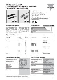
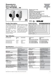
RJCS<br />
<strong>Alarm</strong> Operation<br />
1.1 Current Setpoint<br />
The current setpoint is the<br />
nominal operating current that<br />
is expected when all the heater<br />
loads are functioning properly.<br />
If the heater loads are faulty or<br />
the supply voltage is not close<br />
to the nominal level, the wrong<br />
setpoint will be stored.<br />
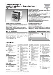
1.2 Initialisation<br />
When the device is shipped,<br />
no setpoint is stored in the<br />
flash memory. Both green<br />
and red LEDs will flash intermittently<br />
to indicate that a<br />
setpoint must be stored<br />
using the TEACH procedure.<br />
The load will not go on when<br />
the control is applied so long<br />
as a TEACH command is<br />
succesful.<br />
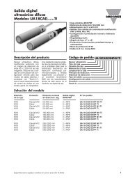
1.3 Local Functions<br />
Local functions can be activated<br />
by using the push<br />
button on the front of the<br />
device. While an alarm is<br />
being issued by any SSR<br />
connected to the common<br />
alarm line or a remote command<br />
is being issued, no<br />
local commands are accepted.<br />
the device will return to normal<br />
operation. If the alarm<br />
condition is still active, the<br />
device will automatically go<br />
back to alarm status.<br />
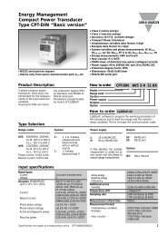
1.3.3 Local TEST<br />
In the absence of a signal on<br />
the “control input” terminal, a<br />
local TEST can be made by<br />
pressing and holding the button<br />
for 5 seconds. After the red<br />
LED flashes 5 times, release<br />
the button. The device will<br />
switch ON the loads for 1 second.<br />
This test detects if there is<br />
an under-current or heater<br />
break alarm condition.<br />
1.4 Remote Setup<br />
Procedure<br />
Remote functions can be<br />
activated <strong>with</strong> a PLC or any<br />
other logic controller by<br />
applying timed pulses to the<br />
alarm terminal: >10V for<br />
RJCS...PO and