50 Amp/with Alarm
50 Amp/with Alarm
50 Amp/with Alarm

You also want an ePaper? Increase the reach of your titles
YUMPU automatically turns print PDFs into web optimized ePapers that Google loves.
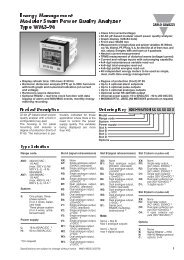
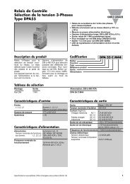
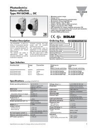
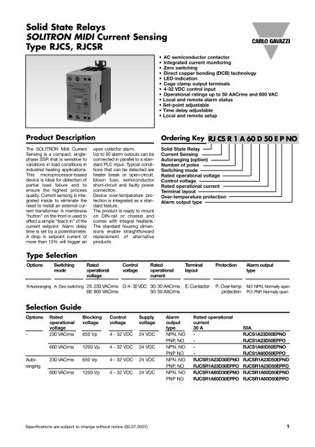
Solid State Relays<br />
SOLITRON MIDI Current Sensing<br />
Type RJCS, RJCSR<br />
Product Description Ordering Key<br />
The SOLITRON Midi Current<br />
Sensing is a compact, singlephase<br />
SSR that is sensitive to<br />
variations in load conditions in<br />
industrial heating applications.<br />
This microprocessor-based<br />
device is ideal for detection of<br />
partial load failure and to<br />
ensure the highest process<br />
quality. Current sensing is integrated<br />
inside to eliminate the<br />
need to install an external current<br />
transformer. A membrane<br />
“button” on the front is used to<br />
effect a simple “teach in” of the<br />
current setpoint. <strong>Alarm</strong> delay<br />
time is set by a potentiometer.<br />
A drop in setpoint current of<br />
more than 13% will trigger an<br />
Type Selection<br />
open collector alarm.<br />
Up to <strong>50</strong> alarm outputs can be<br />
connected in parallel to a standard<br />
PLC input. Typical conditions<br />
that can be detected are<br />
heater break or open-circuit,<br />
blown fuse, semiconductor<br />
short-circuit and faulty power<br />
connection.<br />
Device over-temperature protection<br />
is integrated as a standard<br />
feature.<br />
The product is ready to mount<br />
on DIN-rail or chassis and<br />
comes <strong>with</strong> integral heatsink.<br />
The standard housing dimensions<br />
enable straightforward<br />
replacement of alternative<br />
products.<br />
• AC semiconductor contactor<br />
• Integrated current monitoring<br />
• Zero switching<br />
• Direct copper bonding (DCB) technology<br />
• LED-indication<br />
• Cage clamp output terminals<br />
• 4-32 VDC control input<br />
• Operational ratings up to <strong>50</strong> AACrms and 600 VAC<br />
• Local and remote alarm status<br />
• Set-point adjustable<br />
• Time delay adjustable<br />
• Local and remote setup<br />
Solid State Relay<br />
Current Sensing<br />
Autoranging (option)<br />
Number of poles<br />
Switching mode<br />
Rated operational voltage<br />
Control voltage<br />
Rated operational current<br />
Terminal layout<br />
Over-temperature protection<br />
<strong>Alarm</strong> output type<br />
Options Switching Rated Control Rated Terminal Protection <strong>Alarm</strong> output<br />
mode operational voltage operational layout type<br />
voltage current<br />
R:Autoranging A: Zero switching 23: 230 VACrms D: 4 - 32 VDC 30: 30 AACrms E: Contactor P: Over-temp. NO: NPN, Normally open<br />
60: 600 VACrms <strong>50</strong>: <strong>50</strong> AACrms protection PO: PNP, Normally open<br />
Selection Guide<br />
RJ CS R 1 A 60 D <strong>50</strong> E P NO<br />
Options Rated Blocking Control Supply <strong>Alarm</strong> Rated operational<br />
operational voltage voltage voltage output current<br />
voltage type 30 A <strong>50</strong>A<br />
- 230 VACrms 6<strong>50</strong> Vp 4 - 32 VDC 24 VDC NPN, NO - RJCS1A23D<strong>50</strong>EPNO<br />
PNP, NO - RJCS1A23D<strong>50</strong>EPPO<br />
600 VACrms 1200 Vp 4 - 32 VDC 24 VDC NPN, NO - RJCS1A60D<strong>50</strong>EPNO<br />
PNP NO - RJCS1A60D<strong>50</strong>EPPO<br />
Auto- 230 VACrms 6<strong>50</strong> Vp 4 - 32 VDC 24 VDC NPN, NO RJCSR1A23D30EPNO RJCSR1A23D<strong>50</strong>EPNO<br />
ranging PNP, NO RJCSR1A23D30EPPO RJCSR1A23D<strong>50</strong>EPPO<br />
600 VACrms 1200 Vp 4 - 32 VDC 24 VDC NPN, NO RJCSR1A60D30EPNO RJCSR1A60D<strong>50</strong>EPNO<br />
PNP NO RJCSR1A60D30EPPO RJCSR1A60D<strong>50</strong>EPPO<br />
Specifications are subject to change <strong>with</strong>out notice (05.07.2007) 1
RJCS<br />
General Specifications<br />
Input Specifications<br />
Control voltage range 4 - 32 VDC<br />
Pick-up voltage 3.8 VDC<br />
Reverse voltage A1-A4, A2-A4 32 VDC<br />
Drop-out voltage 1.2 VDC<br />
Maximum control input current 1.5 mA<br />
Response time pick-up ≤ 1/2 cycle<br />
Response time drop-out ≤ 1/2 cycle<br />
Supply Specifications<br />
Power supply voltage, Vcc 24 VDC ± 15%<br />
Max. supply current 22 mA (per device)<br />
Max. PLC current @ 24VDC 275 µA (per device)<br />
during normal conditions<br />
<strong>Alarm</strong> Specifications<br />
Output current, io<br />
Output voltage<br />
≤<strong>50</strong> mADC<br />
NPN 1 + 0.15io<br />
PNP Vcc - 1 - 0.15io<br />
No. of outputs in parallel ≤<strong>50</strong><br />
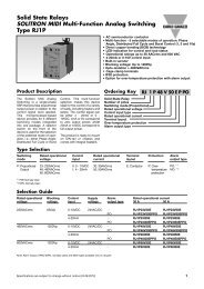
Dissipation Curve<br />
RJCS.1.23.. RJCS.1.60..<br />
Operational voltage range 24 to 265 VAC 42 to 660 VAC<br />
Blocking voltage 6<strong>50</strong> Vp 1200 Vp<br />
Operational frequency range 45 to 65 Hz 45 to 65 Hz<br />
Power factor ≥ 0.5 @ 230 VACrms ≥ 0.5 @ 600 VACrms<br />
Approvals UL, cUL<br />
CE-marking Yes<br />
Supply status indication Green LED, half intensity<br />
Control status indication Green LED<br />
Over-temperature alarm trip indication Red LED, intermittent<br />
<strong>Alarm</strong> indication (excpect for over-temperature trip) Red LED<br />
45W<br />
40W<br />
35W<br />
30W<br />
25W<br />
20W<br />
15W<br />
10W<br />
5W<br />
0W<br />
0A 5A 10A 15A 20A 25A 30A 35A 40A 45A <strong>50</strong>A<br />
30A<br />
<strong>50</strong>A<br />
Housing Specifications<br />
Weight Approx. 4<strong>50</strong> g<br />
Housing material PBT Flame retardant<br />
Control terminal cable size<br />
Min 1 x 0.5 mm 2 (1 x AWG20)<br />
Max 1 x 4.0 mm 2 (1 x AWG12) or<br />
2 x 2.5 mm 2 (2 x AWG14)<br />
Mounting torque max. 0.6 Nm Posidriv 0 bit<br />
Control terminal screws M3<br />
Power terminal cable size<br />
Min 1 x 4 mm 2 (1 x AWG12)<br />
Max 1 x 25 mm 2 (1 x AWG3) or<br />
2 x 10 mm 2 (2 x AWG6)<br />
Mounting torque max. 2.5 Nm Posidriv 2 bit<br />
Power terminal screws M5<br />
Thermal Specifications<br />
Operating temperature -20 to +70ºC (-4 to +158 ˚F)<br />
Storage temperature -40 to +100ºC (-40 to +212 ˚F)<br />
Isolation<br />
Rated isolation voltage<br />
Input to output ≥ 4000 VACrms<br />
Output to case ≥ 4000 VACrms<br />
2 Specifications are subject to change <strong>with</strong>out notice (05.07.2007)
RJCS<br />
Output Specifications<br />
RJCS.1...30 RJCS.1...<strong>50</strong><br />
Rated operational current<br />
AC51 @Ta=25ºC 30 AACrms <strong>50</strong> AACrms<br />
Measuring range RJCS1A... - 8 - <strong>50</strong> ACrms<br />
RJCSR1A... 0.3 - 30 AACrms 0.5 - <strong>50</strong> AACrms<br />
Min. TEACH current RJCS1A... - 8 AACrms<br />
RJCSR1A... 0.3 AACrms 0.5 AACrms<br />
Min. partial load current RJCS1A... - 1.3 AACrms<br />
RJCSR1A... 0.05 AACrms 0.083 AACrms<br />
Non rep. surge current (t=10ms) 600 Ap 1900 Ap<br />
Off-state leakage current @rated voltage and frequency < 5 mArms < 5 mArms<br />
I2t for fusing (t = 10 ms) 1800 A2s 18000 A2s On-state voltage drop @ rated current 1.6 Vrms 1.6 Vrms<br />
Critical dV/dt off-state 1000 V/µs 1000 V/µs<br />
Connection Examples<br />
~<br />
~<br />
LOAD<br />
3A1: Control input 4-32VDC<br />
5A3: <strong>Alarm</strong> output PNP open<br />
collector<br />
6A4: Supply 24VDC<br />
4A2: GND 0V<br />
24 VDC<br />
+<br />
_<br />
<strong>Alarm</strong>/Remote<br />
1L1 5A3 3A1<br />
2T1 6A4 4A2<br />
+ 4-32VDC<br />
24 VDC + - 0V<br />
1L1 Alm Ctrl<br />
1<strong>50</strong>E<br />
2T1 24V GND<br />
Notes:<br />
1. Control input (terminal A1) and 24VDC supply (terminal A3) must have common ground<br />
2. RJCSc ... and PLC should be sourced from the same 24VDC supply<br />
3. RJCSc ... PO and RJCSc ...NO should not be connected to the same alarm line<br />
4. It is recommended that up to 6 identical loads are connected in parallel<br />
100k<br />
~<br />
~<br />
LOAD<br />
3A1: Control input 4-32VDC<br />
5A3: <strong>Alarm</strong> output NPN open<br />
collector<br />
6A4: Supply 24VDC<br />
4A2: GND 0V<br />
1L1 Alm Ctrl<br />
2T1 24V GND<br />
<strong>Alarm</strong>/Remote<br />
1L1 5A3 3A1<br />
2T1 6A4 4A2<br />
+ 4-32VDC<br />
24 VDC + - 0V<br />
Specifications are subject to change <strong>with</strong>out notice (05.07.2007) 3<br />
100k<br />
1<strong>50</strong>E<br />
OUTPUT INPUT<br />
OUTPUT<br />
OUTPUT<br />
24V<br />
PLC<br />
GND
RJCS<br />
<strong>Alarm</strong> Operation<br />
1.1 Current Setpoint<br />
The current setpoint is the<br />
nominal operating current that<br />
is expected when all the heater<br />
loads are functioning properly.<br />
If the heater loads are faulty or<br />
the supply voltage is not close<br />
to the nominal level, the wrong<br />
setpoint will be stored.<br />
1.2 Initialisation<br />
When the device is shipped,<br />
no setpoint is stored in the<br />
flash memory. Both green<br />
and red LEDs will flash intermittently<br />
to indicate that a<br />
setpoint must be stored<br />
using the TEACH procedure.<br />
The load will not go on when<br />
the control is applied so long<br />
as a TEACH command is<br />
succesful.<br />
1.3 Local Functions<br />
Local functions can be activated<br />
by using the push<br />
button on the front of the<br />
device. While an alarm is<br />
being issued by any SSR<br />
connected to the common<br />
alarm line or a remote command<br />
is being issued, no<br />
local commands are accepted.<br />
the device will return to normal<br />
operation. If the alarm<br />
condition is still active, the<br />
device will automatically go<br />
back to alarm status.<br />
1.3.3 Local TEST<br />
In the absence of a signal on<br />
the “control input” terminal, a<br />
local TEST can be made by<br />
pressing and holding the button<br />
for 5 seconds. After the red<br />
LED flashes 5 times, release<br />
the button. The device will<br />
switch ON the loads for 1 second.<br />
This test detects if there is<br />
an under-current or heater<br />
break alarm condition.<br />
1.4 Remote Setup<br />
Procedure<br />
Remote functions can be<br />
activated <strong>with</strong> a PLC or any<br />
other logic controller by<br />
applying timed pulses to the<br />
alarm terminal: >10V for<br />
RJCS...PO and
RJCS<br />
Example<br />
Let the alarm delay setting be<br />
2s (min). If the full load current<br />
is set at 30A, then there will be<br />
an alarm condition if the current<br />
is under 26.1A for more<br />
<strong>Alarm</strong> Operation<br />
Panel Mounting<br />
120 mm<br />
22,5 mm<br />
than 2s. (Any fluctutation in<br />
the load current that is present<br />
for
RJCS<br />
Derating vs. Spacing Curves<br />
Load Current (AACrms)<br />
Note: Based on 100% duty cycle<br />
Load Current (AACrms)<br />
Note: Based on 100% duty cycle<br />
Surrounding temp. (˚C)<br />
RJCS......30....<br />
Surrounding temp. (˚C) RJCS......<strong>50</strong>....<br />
6 Specifications are subject to change <strong>with</strong>out notice (05.07.2007)
RJCS<br />
Setup and <strong>Alarm</strong>s<br />
Current under-range<br />
detected during TEACH<br />
Heater break alarm<br />
Note: Above shows pulses for PNP device<br />
Specifications are subject to change <strong>with</strong>out notice (05.07.2007) 7