Groove Welds Unit 16 - Goodheart-Willcox
Groove Welds Unit 16 - Goodheart-Willcox
Groove Welds Unit 16 - Goodheart-Willcox

Create successful ePaper yourself
Turn your PDF publications into a flip-book with our unique Google optimized e-Paper software.
This sample chapter is for review purposes only. Copyright © The <strong>Goodheart</strong>-<strong>Willcox</strong> Co., Inc. All rights reserved.<br />
After completing <strong>Unit</strong> <strong>16</strong>, you will be able to:<br />
❍ Differentiate a groove weld from other types of welds.<br />
❍ Interpret dimensions for preparing groove welds, including the depth of<br />
preparation, groove angle, bevel angle, and root opening size.<br />
❍ Determine the preparation size and effective throat of groove welds.<br />
❍ Apply groove weld dimensioning standards.<br />
❍ Interpret surface finish and contour symbols.<br />
❍ Interpret melt-through, back, and backing weld symbols.<br />
❍ Explain uses for backing, joint spacers, and runoff weld tabs.<br />
Key Words<br />
backing<br />
bevel angle<br />
effective throat<br />
flare-groove welds<br />
groove angle<br />
groove face<br />
<strong>Unit</strong> <strong>16</strong><br />
<strong>Groove</strong> <strong>Welds</strong><br />
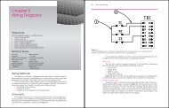
<strong>Groove</strong> welds are made in the space between two sections of metal, Figure <strong>16</strong>-1.<br />
With the exception of the square-groove and flare-groove joints, one or more of<br />
the members being joined is prepared by removing metal to form a V-, J-, or<br />
U-shaped trough. This joint preparation provides for deeper or full penetration of<br />
Square-groove<br />
welds<br />
Single-bevel-groove weld Double-bevel-groove weld Single-V-groove weld<br />
Double-V-groove weld Double-J-groove weld<br />
Single-J-groove weld<br />
Figure <strong>16</strong>-1.<br />
Single-groove and double-groove weld joints are shown.<br />
groove radii<br />
joint root<br />
joint spacers<br />
root faces<br />
root opening<br />
runoff weld tabs<br />
197<br />
198 Welding Print Reading<br />
the weld into the joint and provides clearance for the electrode.<br />
Burning, grinding, arc gouging, chiseling, or<br />
machining removes the metal.<br />
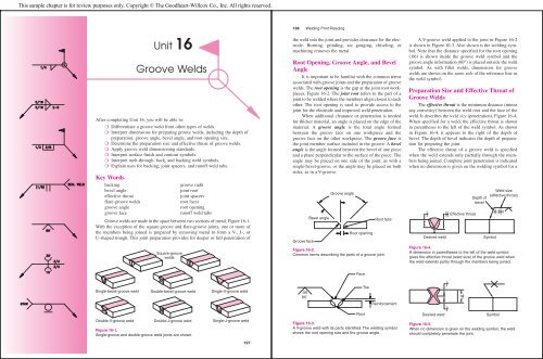
Root Opening, <strong>Groove</strong> Angle, and Bevel<br />
Angle<br />
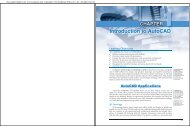
It is important to be familiar with the common terms<br />
associated with groove joints and the preparation of groove<br />
welds. The root opening is the gap at the joint root workpieces,<br />
Figure <strong>16</strong>-2. The joint root refers to the part of a<br />
joint to be welded where the members align closest to each<br />
other. The root opening is used to provide access to the<br />
joint for the electrode and improved weld penetration.<br />
When additional clearance or penetration is needed<br />
for thicker material, an angle is placed on the edge of the<br />
material. A groove angle is the total angle formed<br />
between the groove face on one workpiece and the<br />
groove face on the other workpiece. The groove face is<br />
the joint member surface included in the groove. A bevel<br />
angle is the angle formed between the bevel of one piece<br />
and a plane perpendicular to the surface of the piece. The<br />
angle may be placed on one side of the joint, as with a<br />
single-bevel-groove, or the angle may be placed on both<br />
sides, as in a V-groove.<br />
<strong>Groove</strong> face<br />
Bevel angle<br />
<strong>Groove</strong> angle<br />
Root opening<br />
Root face<br />
Figure <strong>16</strong>-2.<br />
Common terms describing the parts of a groove joint.<br />
.06<br />
60˚<br />
Face<br />
Root<br />
Toe<br />
Reinforcement<br />
Figure <strong>16</strong>-3.<br />
A V-groove weld with its parts identified. The welding symbol<br />
shows the root opening size and the groove angle.<br />
A V-groove weld applied to the joint in Figure <strong>16</strong>-2<br />
is shown in Figure <strong>16</strong>-3. Also shown is the welding symbol.<br />
Note that the distance specified for the root opening<br />
(.06) is shown inside the groove weld symbol and the<br />
groove angle information (60°) is placed outside the weld<br />
symbol. As with fillet welds, dimensions for groove<br />
welds are shown on the same side of the reference line as<br />
the weld symbol.<br />
Preparation Size and Effective Throat of<br />
<strong>Groove</strong> <strong>Welds</strong><br />
The effective throat is the minimum distance (minus<br />
any convexity) between the weld root and the face of the<br />
weld. It describes the weld size (penetration), Figure <strong>16</strong>-4.<br />
When specified for a weld, the effective throat is shown<br />
in parentheses to the left of the weld symbol. As shown<br />
in Figure <strong>16</strong>-4, it appears to the right of the depth of<br />
bevel. The depth of bevel indicates the depth of preparation<br />
for preparing the joint.<br />
The effective throat of a groove weld is specified<br />
when the weld extends only partially through the members<br />
being joined. Complete joint penetration is indicated<br />
when no dimension is given on the welding symbol for a<br />
3<br />
4<br />
15 Effective throat<br />
<strong>16</strong><br />
Depth of<br />
bevel<br />
Desired weld Symbol<br />
Weld size<br />
(effective throat)<br />
3 15<br />
4 ( <strong>16</strong> )<br />
Figure <strong>16</strong>-4.<br />
A dimension in parentheses to the left of the weld symbol<br />
gives the effective throat (weld size) of the groove weld when<br />
the weld extends partly through the members being joined.<br />
Desired weld<br />
3<br />
4<br />
3<br />
4<br />
1<br />
12<br />
Symbol<br />
Figure <strong>16</strong>-5.<br />
When no dimension is given on the welding symbol, the weld<br />
should completely penetrate the joint.
This sample chapter is for review purposes only. Copyright © The <strong>Goodheart</strong>-<strong>Willcox</strong> Co., Inc. All rights reserved.<br />
single-groove or a symmetrical double-groove weld.<br />
Figure <strong>16</strong>-5 illustrates complete weld penetration for a<br />
double-groove joint.<br />
A dimension not in parentheses on the left of a<br />
bevel-, V-, J-, or U-groove weld symbol (in cases where<br />
the effective throat is not specified, or is specified elsewhere<br />
on the print) indicates the size of the weld preparation<br />
only, Figure <strong>16</strong>-6. No such dimension is needed<br />
with a square-groove weld.<br />
Optional groove preparation with complete penetration<br />
is indicated when the letters CJP are shown in the tail<br />
of the reference line. No weld symbol is used, as in<br />
Figure <strong>16</strong>-7.<br />
The weld size of a flare-groove weld is considered<br />
only to the tangent point (the point where the curved surfaces<br />
meet), Figure <strong>16</strong>-8.<br />
30° 7<br />
7 8<br />
8 30°<br />
Joint preparation Symbol<br />
Figure <strong>16</strong>-6.<br />
Weld preparation only is indicated if no dimension is in<br />
parentheses to the left of the bevel-, V-, J-, or U-groove<br />
weld symbol.<br />
Desired weld Symbol<br />
CJP<br />
Figure <strong>16</strong>-7.<br />
The letters CJP in the tail of the reference line indicate optional<br />
groove preparation with complete weld penetration.<br />
General Use of <strong>Groove</strong> Weld Symbol<br />
Different conventions are used for groove welding<br />
symbols depending on the dimensions that are specified<br />
and the information required. As previously discussed,<br />
dimensions for the preparation of groove welds are<br />
shown on the same side of the reference line as the weld<br />
symbol. See Figure <strong>16</strong>-9. This example shows a J-groove<br />
weld. The information specified includes the depth of<br />
preparation, groove angle, and root opening.<br />
0<br />
3<br />
4<br />
30°<br />
Depth of<br />
preparation<br />
<strong>Unit</strong> <strong>16</strong> <strong>Groove</strong> <strong>Welds</strong> 199<br />
Figure <strong>16</strong>-8.<br />
Flare-groove weld size extends only to the tangent points of<br />
the joint members.<br />
Root<br />
opening<br />
3<br />
0<br />
4 30°<br />
Desired preparation Symbol<br />
<strong>Groove</strong><br />
angle<br />
3<br />
0<br />
4 30°<br />
Figure <strong>16</strong>-9.<br />
Specifications for the preparation of an arrow side J-groove weld.<br />
Double-groove welds are dimensioned on both<br />
sides of the reference line if no general note appears<br />
on the print, Figure <strong>16</strong>-10. If the welds differ in size,<br />
they are dimensioned as in Figure <strong>16</strong>-11. <strong>Groove</strong><br />
welding symbols will not include dimensions when a<br />
general note determining groove weld size appears on<br />
2<br />
2<br />
30°<br />
R<br />
R<br />
30°<br />
0<br />
E<br />
R = User's standard<br />
Figure <strong>16</strong>-10.<br />
Unless there is a general note on the print, double-groove<br />
welds are dimensioned on both sides of the reference line.<br />
S<br />
S(E)<br />
S = Depth extends from<br />
point of tangency<br />
to top of member<br />
E = Effective throat<br />
Desired weld Symbol<br />
2<br />
2<br />
30°<br />
0<br />
0<br />
30°<br />
Desired weld Symbol<br />
200 Welding Print Reading<br />
the print, Figure <strong>16</strong>-12. When a break in the arrow is used<br />
with bevel- and J-groove welds, the arrow points toward<br />
the member to be beveled, Figure <strong>16</strong>-13.<br />
60°<br />
60°<br />
3<br />
4 7 8<br />
Weld specified<br />
3 1 90°<br />
8(<br />
2)<br />
3<br />
4(<br />
)<br />
60°<br />
7<br />
8<br />
3<br />
1 8<br />
2<br />
90°<br />
Desired weld Symbol<br />
Figure <strong>16</strong>-11.<br />
<strong>Groove</strong> welds differing in size are dimensioned in the manner<br />
shown.<br />
NOTE-<br />
ALL V-GROOVE WELDS SHALL<br />
HAVE A 60° GROOVE ANGLE<br />
UNLESS OTHERWISE NOTED.<br />
Note and symbol<br />
Figure <strong>16</strong>-12.<br />
If a general note indicating weld size is on the print, no groove<br />
weld dimensions are given with the welding symbol.<br />
<strong>Groove</strong> Dimensions<br />
Many companies have established their own standards<br />
for groove weld dimensions. These standards are<br />
observed unless otherwise noted on the print. When company<br />
standards for groove welds are not indicated, the<br />
following applies:<br />
❍ The root opening is indicated inside the weld<br />
symbol, Figure <strong>16</strong>-14.<br />
❍ The groove angle or bevel angle is specified,<br />
Figure <strong>16</strong>-15.<br />
❍ The groove radii (used to form the shape of<br />
J- or U-groove welds) and root faces (the parts<br />
of the groove face within the joint root) are shown<br />
by cross section, detail, or other means with a<br />
reference on the welding symbol, Figure <strong>16</strong>-<strong>16</strong>.<br />
Figure <strong>16</strong>-13.<br />
A break in an arrow always points toward the member of the<br />
single-bevel-groove or J-groove joint to be beveled.<br />
1<br />
8<br />
Figure <strong>16</strong>-14.<br />
The root opening of a groove weld is specified inside the weld<br />
symbol when standards are not otherwise indicated.<br />
1<br />
8<br />
Desired weld Symbol<br />
15°<br />
50°<br />
60°<br />
90°<br />
45°<br />
45°<br />
Other side bevel-groove<br />
weld symbol<br />
Desired weld Symbol<br />
Figure <strong>16</strong>-15.<br />
Study how groove angles of groove welds are specified.<br />
50°<br />
15°<br />
Desired welds Symbols<br />
45°<br />
45°<br />
90°<br />
60°
This sample chapter is for review purposes only. Copyright © The <strong>Goodheart</strong>-<strong>Willcox</strong> Co., Inc. All rights reserved.<br />
1<br />
TO<br />
3<br />
<strong>16</strong> <strong>16</strong><br />
ANGLE X<br />
45° MIN<br />
20° MIN<br />
12° MIN<br />
X<br />
R 1 4 MIN<br />
3<br />
<strong>16</strong> MAX.<br />
POSITION<br />
ALL<br />
F, V, O<br />
F<br />
DETAIL E<br />
(EXCEPT FROM DWG B2345,<br />
"GROOVE WELD STANDARDS")<br />
Figure <strong>16</strong>-<strong>16</strong>.<br />
<strong>Groove</strong> radii and root faces of U- and J-groove welds are<br />
shown by cross section, detail, or other means with a welding<br />
symbol reference.<br />
Surface Finish and Contour of <strong>Groove</strong><br />
<strong>Welds</strong><br />
The buildup of the groove weld above the surface of<br />
the base material is called reinforcement. Sometimes the<br />
welding symbol specifies that the reinforcement be minimized<br />
or removed.<br />
<strong>Groove</strong> welds to be made approximately flush (but<br />
not generally finished flush mechanically) are specified<br />
by a flush contour symbol. This symbol is placed above<br />
the weld symbol, as in Figure <strong>16</strong>-17. <strong>Groove</strong> welds to be<br />
Weld deposited<br />
flush with<br />
base metal<br />
SEE DWG B2345<br />
DETAIL E<br />
Symbol<br />
Desired weld Symbol<br />
Figure <strong>16</strong>-17.<br />
A flush contour symbol is placed above the weld symbol when<br />
the groove weld is to be made approximately flush<br />
and without the use of grinding, chipping, hammering, or<br />
machining.<br />
made flush by mechanical means are specified with a<br />
flush contour symbol and the method of making the weld<br />
flush, Figure <strong>16</strong>-18. <strong>Groove</strong> welds to be finished mechanically<br />
with a convex contour are specified by a convex<br />
contour symbol. The method of finishing the weld to a<br />
convex contour is also given, Figure <strong>16</strong>-19.<br />
Weld made flush<br />
with base metal<br />
by grinding<br />
Desired weld Symbol<br />
Figure <strong>16</strong>-18.<br />
<strong>Groove</strong> welds to be made flush mechanically are specified by<br />
a flush contour symbol and by the method to use to make the<br />
weld flush.<br />
Finished to smooth<br />
convex contour<br />
by machining<br />
<strong>Unit</strong> <strong>16</strong> <strong>Groove</strong> <strong>Welds</strong> 201<br />
Desired weld Symbol<br />
Figure <strong>16</strong>-19.<br />
When groove welds are to be finished mechanically to a flush<br />
contour, they are specified by a convex contour symbol and<br />
the method of finishing.<br />
Melt-Through, Back, and Backing <strong>Welds</strong><br />
The melt-through, back, and backing weld symbols<br />
show that a melt-through to the other side, bead-type<br />
back, or backing weld is needed with a single-groove<br />
weld. Points to remember include:<br />
❍ A back weld is made after the groove weld.<br />
❍ A backing weld is made before the groove weld.<br />
❍ A melt-through is a visible reinforcement produced<br />
in a groove weld from one side.<br />
A note states whether a back or backing weld is to<br />
be made. This note is placed in the tail of the welding<br />
symbol, Figure <strong>16</strong>-20. As shown, a back or backing weld<br />
symbol is located on the side of the reference line that is<br />
opposite the groove weld symbol.<br />
A flush contour symbol, added to the back or backing<br />
weld symbol, indicates the weld should be approximately<br />
flush with the base metal, Figure <strong>16</strong>-21.<br />
If the back or backing weld is to be made flush by<br />
mechanical means, the method of making the weld flush<br />
is added to the flush contour symbol, Figure <strong>16</strong>-22.<br />
When a back or backing weld is to be finished to<br />
a convex contour by mechanical means, a convex contour<br />
symbol and finish symbol are added to the weld<br />
symbol.<br />
G<br />
M<br />
M<br />
202 Welding Print Reading<br />
NOTE-<br />
1. GROOVE WELD MADE BEFORE<br />
WELDING OTHER SIDE.<br />
2.<br />
(ABOVE FOUND ELSEWHERE ON PRINT)<br />
Back weld<br />
Desired welds<br />
Backing weld machined<br />
flush with base metal<br />
Weld deposited flush<br />
with base metal<br />
Symbol<br />
Desired welds Symbol<br />
Desired welds Symbol<br />
Figure <strong>16</strong>-22.<br />
A symbol added above the flush contour symbol identifies the<br />
mechanical method used to finish the weld flush.<br />
With the exception of height, which is optional, no<br />
other back or backing weld dimensions are shown with<br />
the weld symbol, Figure <strong>16</strong>-23. If other dimensions are<br />
required, they are shown on the drawing.<br />
A melt-through weld assures full joint penetration.<br />
The melt-through weld symbol is similar to the back or<br />
backing weld symbol with the bead filled in as shown in<br />
Figure <strong>16</strong>-24. A dimension to the left of the symbol specifies<br />
the amount of melt-through.<br />
M<br />
NOTE 1<br />
Figure <strong>16</strong>-20.<br />
Specifications for a back weld. A note in the tail of the reference<br />
line indicates whether to make a back or backing weld.<br />
NOTE 1<br />
Figure <strong>16</strong>-21.<br />
A flush contour symbol indicates the weld is to be finished<br />
approximately flush with the base metal.<br />
NOTE 2<br />
1<br />
<strong>16</strong><br />
1<br />
<strong>16</strong><br />
Desired weld Symbol<br />
Figure <strong>16</strong>-23.<br />
Only the back or backing weld height dimension is shown on<br />
the welding symbol. If other dimensions are needed, they are<br />
given elsewhere on the print.<br />
1<br />
8<br />
Desired weld Symbol<br />
Figure <strong>16</strong>-24.<br />
The melt-through weld symbol resembles the back or backing<br />
weld symbol, but the bead is filled in. The height of root reinforcement<br />
may appear as a dimension specified to the left of<br />
the melt-through symbol. (American Welding Society)<br />
Backing, Joint Spacers, and Runoff Weld<br />
Tabs<br />
Backing is material placed against the back side of a<br />
joint to withstand molten weld metal, Figure <strong>16</strong>-25. It is<br />
employed when full penetration groove welds are<br />
required and welding can only be done from one side.<br />
Backing is thoroughly penetrated by the weld and usually<br />
left in place.<br />
Backing<br />
Desired weld Symbol<br />
Figure <strong>16</strong>-25.<br />
Backing used in a joint. A specification indicating its use is<br />
shown in the tail of the reference line.<br />
1<br />
8<br />
B-3
This sample chapter is for review purposes only. Copyright © The <strong>Goodheart</strong>-<strong>Willcox</strong> Co., Inc. All rights reserved.<br />
Joint spacers are metal parts inserted in the joint<br />
root as backing and to maintain the root opening during<br />
welding, Figure <strong>16</strong>-26. Joint spacers are sometimes used,<br />
especially if the weld is in thick material and the minimum<br />
possible V-angle is specified. In such welds, the root<br />
must be gouged out completely, including the spacer bar,<br />
before the second side of the groove is welded.<br />
Runoff weld tabs provide an extension of the groove<br />
beyond the pieces being joined when a full-length groove<br />
weld is specified, Figure <strong>16</strong>-27. Runoff tabs provide a<br />
place to strike the arc and material at the end of the weld<br />
to eliminate the weld crater. The angle or contour of the<br />
runoff weld tab must be identical to that of the groove.<br />
Since welding symbols give no indication of the<br />
backing, spacer, or extension bar requirements, note that<br />
unless covered by reference to AWS prequalified joints or<br />
fabricators’ standards, special sketches of the weld profile<br />
are provided.<br />
Flare-<strong>Groove</strong> <strong>Welds</strong><br />
Flare-groove welds are used to join round or formed<br />
metal parts. The groove that is formed when curved surfaces<br />
are placed together does not have straight sides on one or<br />
both members. Two round steel bars laid side-by-side, such<br />
as reinforcing rod, have sides that are curved. The joint that<br />
is formed does not have straight sides like a V-groove weld.<br />
Desired weld<br />
Symbol<br />
Joint<br />
SPEC. 35A<br />
Figure <strong>16</strong>-26.<br />
Joint spacers may be specified when thick sections are welded.<br />
In such welds, the root and joint spacers are gouged out<br />
before the second side of the groove is welded. Specifications<br />
are shown in the reference line tail.<br />
Runoff<br />
bar<br />
Runout plate<br />
or backing<br />
extension<br />
Runoff<br />
tab<br />
Figure <strong>16</strong>-27.<br />
A runoff weld tab is used when a full-length groove weld is<br />
specified. Specifications in the reference line tail or sketches<br />
on the drawing may be used to indicate a runoff weld tab.<br />
Figure <strong>16</strong>-28 shows an example of a flare-V-groove<br />
weld. Either two round parts (members) or two formed<br />
parts (members) can be used to form the V-groove. The<br />
symbol for the flare-V-groove weld can be placed on a<br />
single side, or the symbol can indicate that the weld<br />
should be made on both sides.<br />
The depth dimension for a flare-V-groove weld is<br />
given as the distance from the top of the member to the<br />
point of tangency (where it touches the other member or<br />
part). Figure <strong>16</strong>-29 shows a dimension of .31 to the point<br />
of tangency and a weld size of .25. Notice that the weld<br />
size is placed in parentheses. The weld size is the distance<br />
from the surface of the part to the root of the weld.<br />
1.00<br />
<strong>Unit</strong> <strong>16</strong> <strong>Groove</strong> <strong>Welds</strong> 203<br />
1.00 (.75)<br />
Figure <strong>16</strong>-28.<br />
A flare-V-groove weld applied to a joint formed by two round<br />
parts.<br />
.75<br />
204 Welding Print Reading<br />
For round parts, the first dimension is the radius of<br />
the round part. Figure <strong>16</strong>-28 shows the round bar has a<br />
radius of 1.00 and a weld size of .75.<br />
If only one part is round or formed, then the formed<br />
part and a straight part form a flare-bevel-groove weld.<br />
Figure <strong>16</strong>-30 shows a formed part welded to a straight<br />
.25<br />
<strong>Groove</strong> weld size<br />
Top of<br />
member (part)<br />
Figure <strong>16</strong>-29.<br />
Dimensions for a flare-V-groove weld.<br />
.50 (.25)<br />
.25<br />
Point of<br />
tangency<br />
.31 (.25)<br />
Point of<br />
tangency<br />
Figure <strong>16</strong>-30.<br />
A flare-bevel-groove weld can be formed by one round, or<br />
formed, part, and a straight part.<br />
part. The dimensions used to describe the flare-bevelgroove<br />
weld have the same meaning as those used for the<br />
flare-V-groove weld. The first dimension indicates the<br />
distance from the top of the part to the point of tangency<br />
and the second dimension indicates the size of the weld.<br />
Notice that the first dimension for round parts indicates<br />
the radius of the round part. See Figure <strong>16</strong>-31.<br />
.31<br />
.50<br />
Combination Weld Symbols<br />
Combination weld symbols are used when other types<br />
of welds are required with groove welds. Figure <strong>16</strong>-32<br />
shows a flare-bevel-groove weld with two fillet welds.<br />
The weld symbols specify a fillet weld over the flarebevel-groove<br />
weld on the arrow side, and a fillet weld on<br />
the other side. The dimensions for the combination symbol<br />
are applied in the same manner as those used for the<br />
flare-groove weld symbol and the fillet weld symbol.<br />
0.75<br />
1.00 (.75)<br />
1.00<br />
Figure <strong>16</strong>-31.<br />
Dimensions for a flare-bevel-groove weld joining a round part<br />
to a straight part. The first dimension in the welding symbol<br />
indicates the distance from the top of the part to the point of<br />
tangency (the radius of the round part) and the second dimension<br />
indicates the size of the weld.<br />
.25<br />
.38 (.18)<br />
.25<br />
Figure <strong>16</strong>-32.<br />
A welding symbol with combination weld symbols for a flarebevel-groove<br />
weld and two fillet welds. The dimensions for<br />
combination weld symbols are applied in the same manner as<br />
those for each type of weld symbol.
This sample chapter is for review purposes only. Copyright © The <strong>Goodheart</strong>-<strong>Willcox</strong> Co., Inc. All rights reserved.<br />
Print Reading Activities<br />
Part I<br />
Identify the groove weld joints shown below. Write your answers in the spaces provided.<br />
1.<br />
3.<br />
5.<br />
7.<br />
9.<br />
<strong>Unit</strong> <strong>16</strong> <strong>Groove</strong> <strong>Welds</strong> 205<br />
Part II<br />
Sketch in the correct welding symbol for each groove weld shown in Part I. Sketch the symbol in the correct location<br />
on the view.<br />
2.<br />
4.<br />
6.<br />
8.<br />
206 Welding Print Reading<br />
Part III<br />
Study the drawings shown and sketch in the welding symbol(s) that will describe each joint.<br />
1.<br />
3.<br />
5.<br />
7.<br />
WELDED<br />
FLUSH<br />
1<br />
2<br />
1<br />
8<br />
GROOVE ANGLES 45°<br />
60°<br />
1<br />
<strong>16</strong><br />
0<br />
9.<br />
7<br />
8 1<br />
GROOVE ANGLE 15°<br />
2.<br />
4.<br />
6.<br />
8.<br />
BEVEL ANGLE 45°<br />
WELDS GROUND FLUSH<br />
1<br />
8<br />
1<br />
<strong>16</strong><br />
1<br />
8<br />
30°<br />
5<br />
1<br />
8<br />
BEVEL ANGLES 45°<br />
FIELD WELD<br />
2
This sample chapter is for review purposes only. Copyright © The <strong>Goodheart</strong>-<strong>Willcox</strong> Co., Inc. All rights reserved.<br />
Part IV<br />
Carefully study the drawing (B577891) below and<br />
answer the following questions.<br />
1. List the name and drawing number.<br />
A.<br />
B.<br />
2. What parts are to be joined by welding?<br />
A.<br />
B.<br />
3. Interpret the types of welds required to make the<br />
weldment (joint of two sections.)<br />
A.<br />
B.<br />
<strong>Unit</strong> <strong>16</strong> <strong>Groove</strong> <strong>Welds</strong> 207<br />
4. Joint and weld specifications can be found _____.<br />
5. What type of welding rod is to be used? _________<br />
6. What special requirements must be observed after<br />
the weldments are made?<br />
A.<br />
B.<br />
7. Have any changes been issued against the drawing?<br />
If there have been, list the number made. ________<br />
208 Welding Print Reading<br />
Part V<br />
Carefully study the drawing (L-725) below and<br />
answer the following questions.<br />
1. List the name and drawing number of the print.<br />
A.<br />
B.<br />
2. How many parts make up the assembly? ________<br />
3. What are the names of the parts that make up the<br />
assembly? _________________________________<br />
4. Is more than one size unit indicated on the print?<br />
5. If more than one size unit is indicated, how many are<br />
there and how is each unit identified?<br />
A.<br />
B.<br />
6. List the stock size required to make each part of the<br />
assembly.<br />
Holder (1)<br />
Holder (2)<br />
Base plate<br />
7. Interpret the type of weld(s) required to make the<br />
weldment(s).<br />
8. What heat treatment is required after welding? ____<br />
9. How is each weld to be inspected? _____________<br />
10. How many holes are drilled in the base? _________<br />
11. The diameter of these holes is _____. ___________<br />
12. How many threaded holes are indicated in the holder?<br />
13. The thread size is _____ and is tapped _____″ deep.<br />
14. Describe how the large hole in the holder is to be made.<br />
15. Is a tolerance indicated for the final diameter? _____<br />
If so, what is it? _____<br />
<strong>16</strong>. What is the size of the key on the base? _________
This sample chapter is for review purposes only. Copyright © The <strong>Goodheart</strong>-<strong>Willcox</strong> Co., Inc. All rights reserved.<br />
Part VI<br />
Explain each of the following welding symbols.<br />
1.<br />
2.<br />
3.<br />
60˚<br />
.38<br />
4.<br />
5.<br />
.12<br />
30˚<br />
<strong>Unit</strong> <strong>16</strong> <strong>Groove</strong> <strong>Welds</strong> 209<br />
G<br />
210 Welding Print Reading<br />
Part VII<br />
Draw the correct weld(s) as indicated by the welding<br />
symbol.<br />
1.<br />
Part VIII<br />
Use print 1104-wrp to answer the following<br />
questions.<br />
1. List the overall length of the support bracket. _____<br />
2. Determine the total number of holes required for the<br />
part.______________________________________<br />
3. Determine the overall maximum height of the part.<br />
4. List the center-to-center distance of the .50 diameter<br />
holes._____________________________________<br />
5. List the typical plate thickness for the support bracket.<br />
6. Determine the maximum angle for the 27° angle of<br />
the gusset. _________________________________<br />
7. What surface requires finishing? _______________<br />
8. Explain the welding symbol at K. ______________<br />
9. Explain the welding symbol at L. ______________<br />
10. Explain the welding symbol at M. ______________<br />
Part IX<br />
Use print 1104-wrp to determine the following<br />
dimensions indicated on the print.<br />
1. A _______________________________________<br />
2. B _______________________________________<br />
3. C _______________________________________<br />
4. D _______________________________________<br />
5. E _______________________________________<br />
6. F _______________________________________<br />
7. G _______________________________________<br />
8. H _______________________________________<br />
9. I _______________________________________<br />
10. J _______________________________________
This sample chapter is for review purposes only. Copyright © The <strong>Goodheart</strong>-<strong>Willcox</strong> Co., Inc. All rights reserved.<br />
<strong>Unit</strong> <strong>16</strong> <strong>Groove</strong> <strong>Welds</strong> 211 212 Welding Print Reading<br />
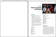
Pipe welding also extends to the auto industry. Shown are stainless steel exhaust manifolds fabricated mainly by welding.<br />
Each unit is carefully inspected because of danger of exhaust gas leakage to the vehicle’s driver and passengers.<br />
(American Iron and Steel Institute)