
You also want an ePaper? Increase the reach of your titles
YUMPU automatically turns print PDFs into web optimized ePapers that Google loves.
759 2<br />
5AB2MAHA@ 5K>MBAH<br />
5AHE= K>AHI '& =@ =>LA<br />
+FOHECDJ ''%<br />
AOAH 5K@ =>H=JHEAI 1?<br />
) HECDJI HAIAHLA@<br />
2=HJ # %& & 4AL )<br />
Keep these important operating instructions.<br />
FAH=JEC 1IJHK?JEI
1JH@K?JE !<br />
)+ 2MAH !<br />
6DA @K=H 4A=H 2=A #<br />
)FEBE?=JE EEJEC =@ +EC 5OIJA $<br />
4ECCEC $<br />
K4=CA 5OIJAI %<br />
2KH E@EGKAH AI HEIGKAI<br />
HIKJ=J @A JAIEI<br />
@=CAHAKIAI<br />
K @EA CAB=DHA L<br />
CABDHE?DA IF=EC AECA<br />
1FHJ=J FAH=JEC<br />
EIJHK?JEI<br />
2KH E@AGKAH EFHJ=J<br />
EIJHK?JEI<br />
K ME?DJECA >AJHEA>I<br />
=MAEIKC K@ KJAH<br />
D=JI=MAEIKC AECA<br />
+JAJI<br />
6DAIA IO>I E@E?=JA EFHJ=J I=BAJO H FAH=JEC BA=JKHAI E JDEI >AJ =@ JDA ?D=IIEI<br />
,=CAHKI LJ=CAI<br />
HEI B AA?JHE? ID?<br />
2=H= E@E?=H ==HAI FHLAC<br />
@A FAECHI LJ=AI<br />
The Manufacturer:<br />
Safety: EN60065: 1994<br />
EMC: EN55103-1 emmission<br />
2=H= E@E?=H EFHJ=JA<br />
BK?E=H O =JAEEAJ<br />
EIJHK??EAI<br />
5O>I 7IA@<br />
8AHEBOEC ,HELAH 2=HEJO '<br />
6HK>AIDJEC<br />
5=BAJO 5K=HO <br />
4A=H 2=A =@ 1FKJ @KAI ,H=MECI <br />
,EAIEI *=? +LAH<br />
H=A H ?D=IIEI<br />
=IIA ?DIIEI<br />
4=DA @AH ?D=IIEI<br />
2HJA?JELA A=HJD CHK@<br />
6AHHA @A FHJA?JE<br />
,EA I?DKJAH@A<br />
)H=@KH= ?D=IIEI 6EAHH= FHJA??EEIJ=<br />
Declaration of Conformity According to ISO/IEC Guide and EN 45014<br />
Name: Meyer Sound Laboratories, Inc.<br />
Address: 2832 San Pablo Avenue<br />
Berkeley, California 94702-2204, USA<br />
Conforms to the following Product Specifications:<br />
EN55103-2 immunity<br />
The product herewith complies with the requirements<br />
of the Low Voltage Directive 73 / 23 / EEC and<br />
the EMC Directive 89 / 336 / EEC.<br />
Office of Quality Manager<br />
Berkeley, California USA<br />
October 1, 1994<br />
Declares that the product:<br />
Product Name: UPA-<strong>1P</strong>, UPA-2P, UM-<strong>1P</strong>, <strong>USW</strong>-<strong>1P</strong>, UM-100P<br />
Product Options: All<br />
Environmental Specifications for<br />
Meyer Sound Electronics Products:<br />
<strong>Operating</strong> temperature: 0 o to + 45 o<br />
Nonoperating temperature: < -40 o C or > +75 o C<br />
Humidity: to 95% at 35 o C<br />
<strong>Operating</strong> Altitude: to 4600 m (15,000 ft)<br />
Nonoperating altitude: to 6300 m (25,000 ft)<br />
Shock: 30g 11 msec half-sine<br />
on each of 6 sides<br />
Vibration: 10 Hz to 55 Hz (0.010m<br />
peak-to-peak excursion)<br />
Made by Meyer Sound Laborat<br />
Berkeley, California USA<br />
European Office:<br />
Meyer Sound Lab. GmbH<br />
Carl Zeiss Strasse 13<br />
56751 Polch, Germany<br />
U L<br />
U L<br />
LISTED<br />
3K59 C<br />
COMMERCIAL<br />
AUDIO SYSTEM<br />
® ®
1JH@K?JE<br />
6DA 1JACH=JA@ ,AIEC<br />
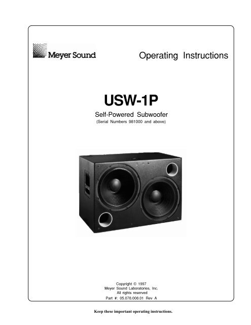
The Meyer <strong>USW</strong>-<strong>1P</strong> self-powered subwoofer is composed of:<br />
• Two 15 inch cone drivers.<br />
phase-corrected, optimized control electronics;<br />
a two-channel amplifier (350 Wrms/ch).<br />
The drivers, control electronics, and amplifier are integrated<br />
into a compact enclosure. The <strong>USW</strong>-<strong>1P</strong> paired with the UPA-P<br />
Series is ideally suited for compact, high-powered PA applications,<br />
such as main PA, churches, 5.1 systems, and theatres.<br />
The <strong>USW</strong>-<strong>1P</strong> is more than a powered version of the Meyer<br />
<strong>USW</strong>-1, The powered <strong>USW</strong>-<strong>1P</strong> implements these significant<br />
design improvements:<br />
The gain structure between the control electronics and<br />
amplifier is perfectly matched.<br />
The amplifier is optimized for the system, providing substantial<br />
power without endangering the drivers.<br />
The integrated design simplifies setup and installation,<br />
eliminates amp racks, and extends the durability<br />
and reliability of the loudspeaker.<br />
)+ 2MAH<br />
The <strong>USW</strong>-<strong>1P</strong> uses a PowerCon locking 3-pole AC mains<br />
connector that prevents inadvertent disconnection. The unit<br />
must have the correct power plug for the AC power in the area<br />
in which it will be used.<br />
Engagement<br />
2<br />
1<br />
Separation<br />
When AC power is applied to the <strong>USW</strong>-<strong>1P</strong>, an Intelligent AC<br />
supply automatically selects the correct operating voltage, allowing<br />
the <strong>USW</strong>-<strong>1P</strong> to be used internationally without manually<br />
setting voltage switches. The Intelligent AC supply performs<br />
the following protective functions to compensate for<br />
hostile conditions on the AC mains:<br />
1<br />
2<br />
3<br />
suppresses high voltage transients up to several kilovolts<br />
filters EMI (radio frequencies and noise present on the<br />
AC line)<br />
sustains operation during low-voltage periods, which<br />
minimizes audio discontinuity<br />
provides soft-start power-up, which eliminates high<br />
inrush current<br />
The <strong>USW</strong>-<strong>1P</strong> can withstand continuous voltages up to 264V<br />
and allows any combination of voltage to GND (i.e. Neutral-<br />
Hot-GND, Hot-Hot-GND). Continuous voltages higher than<br />
264V may damage the unit.<br />
8J=CA 4AGKEHAAJI<br />
The <strong>USW</strong>-<strong>1P</strong> operates safely and without audio discontinuity<br />
if the AC voltage stays within the range 88–264V, 47–63 Hz.<br />
After applying AC power, the system is muted while the circuitry<br />
charges up and stabilizes. After two seconds, the On/<br />
Temp. LED on the user panel illuminates green, the system<br />
unmutes and is ready to pass audio signals. If the On/Temp.<br />
LED does not illuminate or the system does not respond to<br />
audio input after ten seconds, consult the 6HK>AIDJEC<br />
section.<br />
The <strong>USW</strong>-<strong>1P</strong>’s power supply uses stored energy to continue<br />
functioning for about 10 AC cycles if the voltage decreases<br />
below 88V (a condition known as brownout). The precise<br />
length of time the unit functions during brownout depends<br />
on the operating level and how low the voltage drops. The unit<br />
turns off if the voltage does not increase above 88V for 1 to<br />
5 seconds. If the <strong>USW</strong>-<strong>1P</strong> shuts down due to brownout, the<br />
power supply automatically turns on if the voltage returns to<br />
the normal operating range. If the <strong>USW</strong>-<strong>1P</strong> does not turn back<br />
on after ten seconds, consult the 6HK>AIDJEC section.<br />
6- 9A HA?A@ JD=J JDA IKFFO >A FAH=JA@ =J<br />
A=IJ = BAM LJI =M=O BH JDA KFFAH =@ MAH<br />
>K@I B JDA FAH=JEC H=CA J =LE@ FIIE>A<br />
IDKJ@M<br />
!
+KHHAJ 4AGKEHAAJI<br />
Each <strong>USW</strong>-<strong>1P</strong> requires approximately 3 Arms @115V (1.5<br />
Arms@230V) for proper operation, allowing up to five <strong>USW</strong>-<br />
<strong>1P</strong> to be powered from one 15 A circuit. However, we recommend<br />
powering no more than three <strong>USW</strong>-<strong>1P</strong>s per 15 A branch<br />
to allow a 30% margin for peak voltages. The <strong>USW</strong>-<strong>1P</strong><br />
presents a dynamic load to the AC mains which causes the<br />
amount of current to fluctuate between quiet and loud operating<br />
levels. This affects the number of <strong>USW</strong>-<strong>1P</strong>s that can be<br />
used for a given breaker type. Since different types of cables<br />
and circuit breakers heat up and trip at varying rates, it is<br />
essential to understand the types of current ratings and how<br />
they correspond to circuit breaker and cable specifications.<br />
The maximum continuous RMS current is the maximum<br />
RMS current over a duration of at least 10 seconds. It is used<br />
to calculate the temperature increase in cables, which is used<br />
to select cables that conform to electrical code standards. It is<br />
also used to select the rating for slow-reacting thermal breakers.<br />
The maximum burst RMS current is the maximum RMS<br />
current over a one second duration. It is used to select the<br />
rating for most magnetic breakers.<br />
The maximum instantaneous peak current during burst is<br />
used to select the rating for fast-reacting magnetic breakers<br />
and to calculate the peak voltage drop in long AC cables<br />
according to the formula<br />
"<br />
Vpk drop = Ipk x Rtotal cable<br />
Use the table below as a guide to select cables and circuit<br />
breakers with appropriate ratings for your operating voltage<br />
<strong>USW</strong>-<strong>1P</strong> Current Ratings<br />
115V 230V 100V<br />
Idle RMS<br />
0. 25A<br />
0. 13A<br />
0.<br />
3A<br />
Max. Continuous<br />
RMS<br />
8A 4A 10A<br />
Max. Burst<br />
RMS<br />
15A 8A 18A<br />
Max Peak<br />
during<br />
Burst<br />
22A 11A 25A<br />
To determine the minimum total service power required by a<br />
system of <strong>USW</strong>-<strong>1P</strong>s, or other Meyer self-powered speakers,<br />
add their maximum continuous RMS currents together. We<br />
recommend allowing an additional 30% above the minimum<br />
amperage to prevent peak voltage drops at the service entry<br />
and nuisance tripping.<br />
2MAH +A?JH 9EHEC<br />
Use the following AC cable wiring diagram to create international<br />
or special-purpose power connectors:<br />
)+ ?=>A ?H ?@A<br />
If the colors referred to in the diagram don't correspond to the<br />
terminals in your plug, use the following guidelines:<br />
Connect the blue wire to the terminal marked with an<br />
N or colored black.<br />
Connect the brown wire to the terminal marked with an<br />
L or colored red.<br />
Connect the green and yellow wire to the terminal<br />
marked with an E (or ) or colored green (or green and<br />
yellow).<br />
5=BAJO 1IIKAI<br />
, J KIA = CHK@EBJEC =@=FJAH H ?KJ JDA )+<br />
?=>A CHK@ FE<br />
AAF = EGKE@I =M=O BH JDA 759 2 J =LE@<br />
D==H@I BH AA?JHE?= ID?<br />
, J FAH=JA JDA KEJ MEJD MH H BH=OA@ ?=>AI<br />
HAF=?A JDA EA@E=JAO<br />
1B JDA 759 2 ME >A EIJ=A@ KJ@HI ?J=?J<br />
AOAH 5K@ BH EBH=JE =>KJ JDA FJE= H=E<br />
D@ MDE?D FHJA?JI JDA =FEBEAH =@ DA=J IE BH<br />
H=E 9A=JDAH FHJA?JE BH JDA @HELAHI EI =I =L=E<br />
=>A
6DA @K=H 4A=H 2=A<br />
The rear panel of the <strong>USW</strong>-<strong>1P</strong> has two slots for processor<br />
modules. The top slot contains the Audio Input and Control<br />
Module; the bottom slot contains the optional Remote Monitoring<br />
System (RMS) Module. A blank plate covers the<br />
bottom slot if RMS is not installed.<br />
)K@E 1FKJ<br />
There are three, interchangeable Audio Input and Control<br />
Modules with optimized connectors and controls for different<br />
applications. Each module has a 24V Fan connector to power<br />
an optional fan (see fan section on page 6).<br />
Each module uses a three-pin, female XLR audio input<br />
connector with a 10 kΩ balanced input impedance wired with<br />
the following convention:<br />
Pin 1 — 220 kΩ to chassis and earth ground (ESD clamped)<br />
Pin 2 —<br />
Pin 3 —<br />
Signal<br />
Signal<br />
Differential Inputs<br />
Case — Earth (AC) ground and chassis<br />
Pins 2 and 3 carry the input as a differential signal. Use<br />
standard audio cables with XLR connectors for balanced<br />
signal sources. A single audio source can drive multiple <strong>USW</strong>-<br />
<strong>1P</strong>s with a paralleled input loop, creating an unbuffered hardwired<br />
loop connection, with negligible loss in signal level.<br />
For example, since the input impedance of one <strong>USW</strong>-<strong>1P</strong> is 10<br />
kΩ, looping 20 <strong>USW</strong>-<strong>1P</strong> produces a balanced input impedance<br />
of 500Ω. With a 150Ω audio source, the 500Ω load<br />
results in only a 2.28 dB loss.<br />
For drawings of the modules refer to page 12.<br />
FEC )K@E 1FKJ @KA<br />
This standard module uses a balanced, female XLR connector<br />
for audio input and a male XLR loop connector to interconnect<br />
multiple speakers. The audio input connector is hardwired<br />
with pin 2 hot to comply with audio industry standards. The<br />
loop connector, wired in parallel to the audio input, transmits<br />
the input signal even if the <strong>USW</strong>-<strong>1P</strong> is turned off for any<br />
reason.<br />
5KEC )K@E 1FKJ @KA<br />
This module has two balanced female XLR connectors. The<br />
second female XLR connector functions as a summing input.<br />
Applying a signal to one of the inputs results in a normal<br />
signal level. Utilizing both summing inputs creates a correctly<br />
summed mono signal with each input 6 dB below the<br />
level of a single input. This is an effective method for distributing<br />
both sides of a stereo signal to a single <strong>USW</strong>-<strong>1P</strong> without<br />
requiring external level control.<br />
FEC 2=HEJO =@ )JJAK=JEC )K@E<br />
1FKJ @KA<br />
This module has a balanced, female XLR audio input connector,<br />
a male XLR loop connector, an input polarity switch, and<br />
a level attenuator knob. The input polarity switch offers a<br />
convenient method of reversing the phase of the speaker.<br />
When the input polarity switch is in the up (+) position, pin<br />
2 is hot relative to pin 3, resulting in a positive pressure wave<br />
when a positive signal is applied to pin 2. When the switch is<br />
down (-), pin 3 is hot relative to pin 2, resulting in a positive<br />
pressure wave when a positive signal is applied to pin 3. The<br />
level attenuator knob operates between 0 dB (no level attenuation)<br />
in a fully clockwise position to –12 dB in a fully<br />
counterclockwise position.<br />
4AJA EJHEC 5OIJA<br />
The <strong>USW</strong>-<strong>1P</strong> can be equipped to operate with the Remote<br />
Monitoring System (RMS) network and software application.<br />
RMS displays signal and power levels, driver and cooling<br />
fan status, limiter activity, the state of the polarity switch,<br />
attenuator level, and amplifier temperature for all speakers in<br />
the network on a Windows-based PC. RMS can also be configured<br />
to enable speaker muting. RMS is an excellent fielddiagnostic<br />
tool that removes the guesswork from troubleshooting<br />
during a performance. All Meyer Speakers with<br />
RMS can be integrated on the same network. Installing an<br />
RMS module requires only a Phillips screwdriver. Contact<br />
Meyer Sound for more information about RMS.<br />
)FEBE?=JE EEJEC =@<br />
+EC 5OIJA<br />
)FEBE?=JE =@ EEJEC<br />
Each driver in the <strong>USW</strong>-<strong>1P</strong> is powered by one channel of a<br />
proprietary Meyer Sound amplifier utilizing complementary<br />
power MOSFET output stages (class AB, bridged, 350 Wrms/<br />
ch). The <strong>USW</strong>-<strong>1P</strong> employs two separate methods of limiting:<br />
Excursion Limiting which protects the drivers from over<br />
excursion and Sub Channel Limiting which prevents the<br />
drivers from damage due to thermal overload.<br />
Limiter activity for the Excursion and Sub channel is indicated<br />
by two yellow Limit LEDs on the rear panel (the EXC.<br />
Limit LED is above the SUB limit LED). See page 12 for a<br />
diagram of the user panel.<br />
The <strong>USW</strong>-<strong>1P</strong> performs within its acoustical specifications<br />
and operates at a normal temperature if the limit LEDs are on<br />
for no longer than two seconds, and off for at least one second.<br />
#
If either LED remains on for longer than three seconds, that<br />
channel incurs these consequences:<br />
Increasing the input level will not increase the volume.<br />
The system distorts due to clipping and nonlinear<br />
driver operation.<br />
While the <strong>USW</strong>-<strong>1P</strong> limiters fully protect the system under<br />
overload conditions and exhibit smooth sonic characteristics;<br />
we recommend that you do not intentionally drive the<br />
<strong>USW</strong>-<strong>1P</strong> into continuous limiting to attain compression effects.<br />
For applications where large amounts of compression are<br />
required, we recommend using an outboard compressor/limiter<br />
for greater control of limit and compressor effects.<br />
)FEBEAH =JKH= +LA?JE +EC 5OIJA<br />
The <strong>USW</strong>-<strong>1P</strong>’s amplifier employs a natural convection cooling<br />
system that is cooled by the air flowing over the<br />
heatsink. Allow for proper ventilation of fresh air when<br />
using the speaker in tightly packed conditions.<br />
If the temperature of the heatsink reaches 85°C (185°F), the<br />
On/Temp. LED on the rear panel turns from green (On) to red<br />
(Temp.) and the limiter threshold is lowered to a safe level to<br />
prevent the system from overheating. Under high temperature<br />
conditions the output level is reduced 6 dB. When the heatsink<br />
temperature decreases to 75°C (167°F), the On/Temp. LED<br />
changes from red to green and the limiter threshold returns to<br />
normal.<br />
$<br />
6DA DA=JIE HA=?DAI JAFAH=JKHAI KF J &#°<br />
&#°+ @KHEC H= FAH=JE 7IA ANJHAA<br />
?=KJE MDA =FFH=?DEC JDA HA=H B JDA ?=>EAJ<br />
= )IIA>O EJ<br />
While convection cooling is adequate for most applications,<br />
<strong>USW</strong>-<strong>1P</strong>s when driven into continuous limiting under severe<br />
temperature conditions, or where ventilation is restricted,<br />
may benefit from the optional fan kit which increases air flow<br />
to maintain a safe operating temperature.<br />
The easy-to-install fan, powered by the 24V Fan rear panel<br />
connector, blows air directly onto the heatsink. The fan speed<br />
increases as the heatsink temperature rises, which maintains a<br />
safe operating temperature with minimal fan noise. Contact<br />
Meyer Sound to order the fan kit.<br />
2MAH 5KFFO =<br />
The power supply is cooled by a single small internal fan that<br />
turns on low when the unit is first powered up. The fan doubles<br />
its speed as the system is driven with audio. Since the fan<br />
draws air in from, and exhausts it out the back of the cabinet,<br />
there must be at least six inches clearance behind the cabinet,<br />
and adequate air flow.<br />
4ECCEC<br />
The <strong>USW</strong>-<strong>1P</strong> weighs 137 lb (62 kg). The maximum recommended<br />
load for an <strong>USW</strong>-<strong>1P</strong> with aircraft pan fittings is 420<br />
lb (191 kg). This working load is based on a 5:1 safety factor.<br />
The <strong>USW</strong>-<strong>1P</strong> has six rigging brackets (two on top, two on<br />
bottom of the cabinet); each bracket is capable of supporting<br />
the full working load of the cabinet.<br />
There are four types of interchangeable rigging brackets, each<br />
fastened by six Phillips screws:<br />
aircraft pan fittings (ring and stud)<br />
3 /8”-16 nut plates<br />
M-10 x 1.5 metric nut plates<br />
blank plates (if no rigging brackets are requested)<br />
6- 7EJI MEJD KJ F=JAI =HA H=JA@ BH JDA MAECDJ B<br />
A ?=>EAJ O<br />
Rigging load ratings assume a straight tensile pull and that the<br />
cabinet is in new condition with aircraft pan fittings. If these<br />
conditions are not met, the load ratings can be reduced significantly.<br />
Load ratings can also be reduced by age, wear, and<br />
damage. It is important to inspect the rigging hardware regularly<br />
and replace worn or damaged components immediately.<br />
6- ) AOAH 5K@ FH@K?JI KIJ >A KIA@ E<br />
=??H@=?A MEJD ?= IJ=JA BA@AH= =@ E@KIJHO<br />
HACK=JEI 1J EI JDA MAH\I =@H KIAH\I HAIFIE>EEJO<br />
J AL=K=JA JDA HAE=>EEJO B =O HECCEC AJD@ BH<br />
JDAEH =FFE?=JE 4ECCEC IDK@ >A @A O >O<br />
ANFAHEA?A@ FHBAIIE=I
K4=CA 5OIJAI<br />
1JH@K?JHO +?AFJI<br />
The <strong>USW</strong>-<strong>1P</strong> is used to add low frequency SPL to sound<br />
systems. It is optimized to be used with the Meyer UPA-P<br />
series self-powered loudspeakers. It can also be used with<br />
all Meyer Sound loudspeakers. For information on integrating<br />
the <strong>USW</strong>-<strong>1P</strong> with the UPA-P, see the UPA-P Series<br />
<strong>Operating</strong> <strong>Instructions</strong>. For information on using the <strong>USW</strong>-<strong>1P</strong><br />
with other Meyer Sound products please contact Meyer Sound<br />
Technical Support.<br />
Using the <strong>USW</strong>-<strong>1P</strong> in a full-range system is straight forward but<br />
the following concepts are important to consider before installing<br />
a system.<br />
4=@EC<br />
The placement of the <strong>USW</strong>-<strong>1P</strong> in a room or a space is critically<br />
important to the response of the speaker system. A <strong>USW</strong>-<strong>1P</strong><br />
hung in the air with no boundary conditions would not add any<br />
SPL from room loading.<br />
A <strong>USW</strong>-<strong>1P</strong> placed on a floor (half-space loading) will gain<br />
approximately 6 dB compared to its free field response.<br />
6 dB low frequency gain compared to free field.<br />
A <strong>USW</strong>-<strong>1P</strong> placed on a floor and against a wall (quarter-space<br />
loading) will gain approximately 12 dB compared to its free<br />
field response.<br />
12 dB low frequency gain compared to free field.<br />
A <strong>USW</strong>-<strong>1P</strong> placed on the floor in a corner (one-eighth space<br />
loading) will gain approximately 18 dB compared to its free<br />
field response.<br />
18 dB low frequency gain compared to free field.<br />
%
52 LI ,EIJ=?A J *K@=HO<br />
As we have seen on the previous page, the placement of a<br />
<strong>USW</strong>-<strong>1P</strong> on a floor or against a boundary significantly changes<br />
the low frequency response when compared to free field<br />
measurement of the same speaker.<br />
The graph below represents the change in dB SPL for frequencies<br />
under 125 Hz of a single <strong>USW</strong>-<strong>1P</strong> as it is moved away<br />
from a boundary. Distance measured in meters, is based on the<br />
distance from the wall behind the speaker to the acoustical<br />
center of the <strong>USW</strong>-<strong>1P</strong>. All dB SPL measurements are made<br />
with the microphone on axis to the speaker.<br />
Distance to Boundary vs. dB SPL below 125 Hz<br />
&<br />
dB SPL relative to free-space response.<br />
4<br />
2<br />
0<br />
-2<br />
-4<br />
-6<br />
-8<br />
0 0.5 1 1.5 2 2.5 3 3.5 4 4.5<br />
Distance in meters between wall and acoustical center of speaker.<br />
To better understand the graph above, imagine a <strong>USW</strong>-<strong>1P</strong><br />
with a wall behind it. As you move the <strong>USW</strong>-<strong>1P</strong> away from<br />
the wall the graph above shows how the response of the<br />
speaker will change. For example if the <strong>USW</strong>-<strong>1P</strong> is placed 1<br />
meter from a wall and is measured on axis to the speaker, you<br />
will see a -5 dB change in the low frequency as illustrated by<br />
the dotted lines on the graph.<br />
2=HEJO<br />
With the <strong>USW</strong>-<strong>1P</strong> in close-proximity to, and coplanar with,<br />
the UPA-P, or other Meyer Speakers, both speakers should be<br />
set to the same polarity. Separating the subwoofers and main<br />
cabinets in a speaker system by more than 5 feet may require<br />
polarity reversal or a delay line to compensate for the propagation<br />
delay between the speakers and the measurement position.<br />
A=IKHAAJ =@ +HHA?JE 6I<br />
It is recommended that even the most carefully assembled<br />
sound systems be analyzed with precise measurement tools.<br />
We recommend using the Meyer SIM® System II Sound<br />
Analyzer and CP-10 Parametric Equalizer to<br />
choose, place, and array speakers;<br />
measure propagation delays between speakers to set<br />
the correct polarity and delay times;<br />
measure and equalize variations in frequency response<br />
caused by the acoustical environment and the<br />
placement and interaction of speakers.<br />
6DA 8: <br />
The VX-1 is an ideal control option for <strong>USW</strong>-<strong>1P</strong> systems. The<br />
VX-1 is a stereo virtual crossover which allows the user to<br />
adjust the gain, switch between stereo and mono distribution<br />
of two inputs and make shelving EQ adjustments to the left<br />
and right sides of the system.<br />
759 2 MEJD JDA 72)2<br />
The <strong>USW</strong>-<strong>1P</strong> and UPA-P can be configured in a wide variety<br />
of array configurations to suit specific application needs.<br />
Refer to the UPA-P <strong>Operating</strong> <strong>Instructions</strong> for recommended<br />
arrays; or for additional system design ideas, contact Meyer<br />
Sound for the following TechNotes documents on UPA-P<br />
array design:<br />
Two UPA-<strong>1P</strong>s @ 70° Horizontal Splay<br />
(Doc #: 01.990.101.90 A)<br />
Two UPA-<strong>1P</strong>s @ 85° Horizontal Splay<br />
(Doc #: 01.990.101.91 A)<br />
Two UPA-2Ps Tight-pack (Doc #: 01.990.101.92 A).<br />
Three UPA-2Ps Tight-pack (Doc #: 01.990.101.93 A).<br />
These documents are also available on the Meyer Sound<br />
website: http://www.meyersound.com.
8AHEBOEC ,HELAH 2=HEJO<br />
Incorrect driver polarity impairs system performance and<br />
may damage the drivers. All Meyer loudspeakers are shipped<br />
with the drivers in correct alignment.<br />
2=HEJO 1 )@=?AJ K@IFA=AHI<br />
Use the following test procedure to verify the polarity between<br />
two <strong>USW</strong>-<strong>1P</strong>.<br />
1. Establish a reference <strong>USW</strong>-<strong>1P</strong>, a speaker that has not<br />
been tampered with or damaged. Mark this speaker as<br />
the reference.<br />
2. Place the <strong>USW</strong>-<strong>1P</strong> you want to test next to the reference<br />
<strong>USW</strong>-<strong>1P</strong>.<br />
3. Place a measurement microphone 3 feet from the speakers<br />
on the axis between the speakers. See drawing at<br />
bottom of page.<br />
4. Connect a signal source to reference speaker and note<br />
the frequency response and overall level.<br />
5. Apply the same signal to the <strong>USW</strong>-<strong>1P</strong> under test with<br />
the first speaker still connected.<br />
The polarity is correct if the frequency response remains<br />
constant with a 5 to 6 dB SPL increase in amplitude. Broadband<br />
cancellation (decreased overall level) indicates polarity<br />
reversal between cabinets. A 2 to 3 dB SPL increase may<br />
indicate that one of the drivers in the <strong>USW</strong>-<strong>1P</strong> under test is out<br />
of phase, in this case, proceed to the next section.<br />
5E?A F=HEJO HALAHI= ?=KIAI AN?AIIELA @HELAH<br />
AN?KHIE =J DECD IKH?A ALAI KIA @AH=JA<br />
ALAI MDA ?@K?JEC JDAIA JAIJI<br />
Reference<br />
<strong>USW</strong>-<strong>1P</strong><br />
<strong>USW</strong>-<strong>1P</strong><br />
under test<br />
Front of Speaker<br />
Front of Speaker<br />
2=HEJO MEJDE = 759 2<br />
If the driver or circuit wiring has been removed or disassembled<br />
it is essential to check the polarity between drivers<br />
and between adjacent loudspeakers.<br />
Use the following test procedure to verify polarity between<br />
drivers in the same loudspeaker :<br />
1. Place the reference <strong>USW</strong>-<strong>1P</strong> and the <strong>USW</strong>-<strong>1P</strong> under<br />
test side to side so that the drivers are facing the same<br />
direction.<br />
2. Place a measurement microphone 3 feet from the<br />
speakers on the axis between the speakers. See drawing<br />
at bottom of page.<br />
3. Connect a full range signal to the reference <strong>USW</strong>-<strong>1P</strong><br />
loudspeaker and note the frequency response and<br />
sound pressure level.<br />
4. Compare the reference and test <strong>USW</strong>-<strong>1P</strong> results<br />
one at a time. A significant decrease in energy from<br />
40 to 100 Hz in the <strong>USW</strong>-<strong>1P</strong> under test indicates a<br />
driver reversal. Contact Meyer Sound Technical<br />
Support for information on Service Center or field<br />
correction.<br />
5. If the reference and <strong>USW</strong>-<strong>1P</strong> under test have similar<br />
responses, then there is no internal polarity error within<br />
the loudspeaker.<br />
3 feet<br />
Microphone<br />
'
6HK>AIDJEC<br />
This section suggests several possible solutions to some common<br />
problems encountered by <strong>USW</strong>-<strong>1P</strong> users and is not<br />
intended to be a thorough troubleshooting guide. Contact<br />
Meyer Sound for additional information and documentation.<br />
6DA 6AF -, @AI J EKE=JA JDAHA<br />
EI =K@E =@ JDA FMAH IKFFO B= EI<br />
BB<br />
1. Make sure the AC power cable is the correct type for the<br />
regional voltage and that it is securely connected to the<br />
AC inlet then unplug and reconnect the AC cable.<br />
2. Use an AC voltmeter to verify that the AC voltage is<br />
within the ranges 88–264V, 47–63 Hz.<br />
3. Call Meyer Sound Technical Support.<br />
6DA 6AF -, EI EKE=JA@ >KJ JDAHA EI<br />
IK@<br />
1. Verify that the audio source (mixer, EQ, delay) is sending<br />
a valid signal.<br />
2. Make sure the XLR cable is securely fastened to the<br />
XLR audio input connector.<br />
3. Verify that the XLR cable is functioning by substituting<br />
another cable or by using the cable in question in a<br />
working system.<br />
4. Send the audio signal to another speaker to insure signal<br />
presence and that the level is within the proper range.<br />
Turn the source level down before reconnecting the<br />
audio input and increase the level slowly to avoid a<br />
sudden blast of sound.<br />
5. If possible, monitor the audio source with headphones.<br />
0K H EIA EI FH@K?A@ >O JDA IFA=AH<br />
1. Disconnect the audio input. If the noise persists, the<br />
problem is within the <strong>USW</strong>-<strong>1P</strong>. In this case return the<br />
unit to the factory or nearest authorized service center. If<br />
the hum ceases, the noise originates somewhere earlier<br />
in the signal path.<br />
2. Make sure the XLR cable is securely fastened to the<br />
XLR audio input connector.<br />
3. Send the audio signal to another speaker to insure signal<br />
presence and that the level is within the proper range.<br />
Turn the source level down before reconnecting the<br />
audio input and increase the level slowly to avoid a<br />
sudden blast of sound.<br />
5. Hum or noise can be produced by a ground loop. Since<br />
the <strong>USW</strong>-<strong>1P</strong> is effectively ground-lifted, the loop must<br />
be broken elsewhere in the system.<br />
6DA =K@E FH@K?A@ >O JDA IFA=AH EI @EI<br />
JHJA@ H ?FHAIIA@ >KJ JDA EEJ ECDJ EI<br />
J EKE=JA@<br />
1. Make sure the XLR cable is securely fastened to the<br />
XLR audio input connector.<br />
2. Send the audio signal to another speaker to insure that<br />
the level is within the proper range. Turn the source level<br />
down before reconnecting the audio input and increase<br />
the level slowly to avoid a sudden blast of sound.<br />
3. Monitor the audio source with headphones.<br />
6DA =K@E FH@K?A@ >O JDA IFA=AH EI DECDO<br />
?FHAIIA@ =@ JDA EEJ ECDJ EI ?IJ=JO<br />
HA@<br />
1. Turn down the level of the input signal to the speaker<br />
system.<br />
6DAHA EI IK@ >KJ EJ EI @AI J IAA J<br />
>A =J BK FMAH =@ JDA 6AF -, EI<br />
OAM<br />
This occurs in conditions where the heatsink temperature<br />
reaches 85°C (185°F), indicating that the amplifier is thermally<br />
overloaded. The limiter threshold has dropped to a safe<br />
level, so the audio level is reduced.<br />
1. Make sure there is enough clearance above, below, and<br />
behind the unit.<br />
2. Make sure there is sufficient air flow around the unit.<br />
3. Avoid exposing the heatsink to direct sunlight if the<br />
ambient temperature is high.<br />
4. If the ambient temperature is greater than 30° C and this<br />
condition occurs frequently, contact Meyer Sound to<br />
order the optional Fan Kit.<br />
See the section )FEBE?=JE EEJEC =@ +EC<br />
5OIJA on page 6 for a complete discussion about the<br />
cooling system.<br />
6DAHA EI IK@ JDA 6AF -, EI<br />
@E H BB =@ JDA FMAH IKFFO B= EI <br />
DECD IFAA@<br />
This extremely rare event occurs when the power supply overheats,<br />
causing a 1-2 minute interruption in operation. The unit<br />
turns on again when the power supply has cooled sufficiently.<br />
1. Make sure there is at least six inches clearance behind<br />
the unit.<br />
2. Make sure there is sufficient air flow around the unit.<br />
See the section )FEBE?=JE EEJEC =@ +EC<br />
5OIJA on page 6 for a more information about the power<br />
supply’s internal fan and cooling system.
5=BAJO 5K=HO<br />
-CEID H==EI<br />
To reduce the risk of electric shock, disconnect the loudspeaker<br />
from the AC mains before installing audio cable. Reconnect the<br />
power cord only after making all signal connections.<br />
Connect the loudspeaker to a two-pole, three wire grounding mains<br />
receptacle. The receptacle must be connected to a fuse or circuit<br />
breaker. Connection to any other type of receptacle poses a<br />
shock hazard and may violate local electrical codes.<br />
Do not install the loudspeaker in wet or humid locations<br />
without using weather protection equipment from Meyer Sound.<br />
Do not allow water or any foreign object to get inside the<br />
loudspeaker. Do not put objects containing liquid on, or near,<br />
the unit.<br />
To reduce the risk of overheating the loudspeaker, avoid exposing<br />
it to direct sunlight. Do not install the unit near heat emitting<br />
appliances, such as a room heater or stove.<br />
This loudspeaker contains potentially hazardous voltages. Do<br />
not attempt to disassemble the unit. The unit contains no user<br />
serviceable parts. Repairs should be performed only by factory<br />
trained service personnel.<br />
,AKJI?D -IF=<br />
Um die Gefahr eines elektrischen Schlages auf ein Minimum zu<br />
reduzieren, den Lautsprecher vom Stromnetz trennen, bevor<br />
ggf. ein Audio-Schnittstellensignalkabel angeschlossen wird.<br />
Das Netzkabel erst nach Herstellung aller Signalverbindungen<br />
wieder einstecken.<br />
Der Lautsprecher an eine geerdete zweipolige Dreiphasen-<br />
Netzsteckdose anschließen. Die Steckdose muß mit einem<br />
geeigneten Abzweigschutz (Sicherung oder Leistungsschalter)<br />
verbunden sein. Der Anschluß der unterbrechungsfreien<br />
Stromversorgung an einen anderen Steckdosentyp kann zu<br />
Stromschlägen führen und gegen die örtlichen Vorschriften<br />
verstoßen.<br />
Der Lautsprecher nicht an einem Ort aufstellen, an dem sie mit<br />
Wasser oder übermäßig hoher Luftfeuchtigkeit in Berührung<br />
kommen könnte.<br />
Darauf achten, daß weder Wasser noch Fremdkörper in das<br />
Innere den Lautsprecher eindringen. Keine Objekte, die<br />
Flüssigkeit enthalten, auf oder neben die unterbrechungsfreie<br />
Stromversorgung stellen.<br />
Um ein Überhitzen dem Lautsprecher zu verhindern, das Gerät<br />
vor direkter Sonneneinstrahlung fernhalten und nicht in der<br />
Nähe von wärmeabstrahlenden Haushaltsgeräten (z.B. Heizgerät<br />
oder Herd) aufstellen.<br />
Im Inneren diesem Lautsprecher herrschen potentiell gefährliche<br />
Spannungen. Nicht versuchen, das Gerät zu öffnen. Es enthält<br />
keine vom Benutzer reparierbaren Teile. Reparaturen dürfen<br />
nur von ausgebildetem Kundenienstpersonal durchgeführt<br />
werden.<br />
Pour réduire le risque d’électrocution, débrancher la prise<br />
principale de l’haut-parleur, avant d’installer le câble d’interface<br />
allant à l’audio. Ne rebrancher le bloc d’alimentation qu’après<br />
avoir effectué toutes les connections.<br />
Branchez l’haut-parleur dans une prise de courant à 3 dérivations<br />
(deux pôles et la terre). Cette prise doit être munie d’une<br />
protection adéquate (fusible ou coupe-circuit). Le branchement<br />
dans tout autre genre de prise pourrait entraîner un risque<br />
d’électrocution et peut constituer une infraction à la<br />
réglementation locale concernant les installations électriques.<br />
Ne pas installer l’haut-parleur dans un endroit où il y a de l’eau<br />
ou une humidité excessive.<br />
Ne pas laisser de l’eau ou tout objet pénétrer dans l’hautparleur.<br />
Ne pas placer de r´cipients contenant un liquide sur cet<br />
appareil, ni à proximité de celui-ci.<br />
Pour éviter une surchauffe de l’haut-parleur, conserver-la à<br />
l’abri du soleil. Ne pas installer à proximité d’appareils dégageant<br />
de la chaleur tels que radiateurs ou appareils de chauffage.<br />
Ce haut-parleur contient des circuits haute tension présentant<br />
un danger. Ne jamais essayer de le démonter. Il n’y a aucun<br />
composant qui puisse être réparé par l’utilisateur. Toutes les<br />
réparations doivent être effectuées par du personnel qualifié et<br />
agréé par le constructeur.<br />
Para reducir el riesgo de descarga eléctrica, desconecte de la red<br />
el altoparlante antes de instalar el cable de señalización de<br />
interfaz de la segnale. Vuelva a conectar el conductor flexible<br />
de alimentación solamente una vez efectuadas todas las<br />
interconexiones de señalizatción.<br />
Conecte el altoparlante a un tomacorriente bipolar y trifilar con<br />
neutro de puesta a tierra. El tomacorriente debe estar conectado<br />
a la protección de derivación apropiada (ya sea un fusible o un<br />
disyuntor). La conexión a cualquier otro tipo de tomacorriente<br />
puede constituir peligro de descarga eléctrica y violar los<br />
códigos eléctricos locales.<br />
No instale el altoparlante en lugares donde haya agua o humedad<br />
excesiva.<br />
No deje que en el altoparlante entre agua ni ningún objeto<br />
extraño. No ponga objetos con líquidos encima de la unidad ni<br />
cerca de ella.<br />
Para reducir el riesgo de sobrecalentamiento, no exponga la<br />
unidad a los rayos directos del sol ni la instale cerca de<br />
artefactos que emiten calor, como estufas o cocinas.<br />
Este altoparlante contiene niveles de voltaje peligrosos en<br />
potencia. No intente desarmar la unidad, pues no contiene<br />
piezas que puedan ser repardas por el usuario. Las reparaciones<br />
deben efectuarse únicamente por parte del personal de<br />
mantenimiento capacitado en la fábrica.
Rain Hood<br />
screw<br />
Female XLR Input<br />
Male XLR Loop<br />
Rain Hood<br />
screw<br />
4A=H 2=A =@ FJE= @KAI<br />
The user panel and optional modules are described on page 5 of this guide.<br />
! Meyer<br />
Earth /<br />
Chassis<br />
GND Circuit 1<br />
2<br />
3<br />
220k Ω<br />
Case<br />
Push<br />
1<br />
2<br />
3<br />
Fan Connectors<br />
User Panel with RMS option and Standard Looping Audio Input Module.<br />
Case<br />
Earth /<br />
Chassis<br />
24VFan<br />
Input Loop<br />
On / Temp.<br />
Service Wink<br />
Reset<br />
Looping, Polarity, and Attenuating Input Module<br />
Activity<br />
Remote Monitor System<br />
CAUTION: See instruction manual<br />
ATTENTION: Voir le cahier d'instruction<br />
GND Circuit 1 1 10k Ω Balanced<br />
2 2 Ω<br />
3 +<br />
3 -<br />
220k Ω<br />
Input<br />
Push Push<br />
Loop<br />
-<br />
Summing Audio Input Module<br />
+<br />
24VFan<br />
GND Circuit<br />
220k Ω<br />
1<br />
1k Ω Each<br />
Push Ω Each<br />
2<br />
2<br />
1 25k Ω Balanced<br />
+ Ω<br />
-<br />
Push<br />
3 3<br />
Earth /<br />
Chassis<br />
Case<br />
24VFan<br />
Inputs<br />
Summing Inputs<br />
-<br />
+<br />
Looping Audio Input<br />
Network<br />
Limit<br />
Sound, Berkeley, CA. USA<br />
AC Input<br />
100-240V ~<br />
50-60Hz 4A MAX<br />
UX RATING LABEL<br />
A/W 30.076.069.01,<br />
REVISION. A<br />
11/12/97 cmc<br />
Looping Polarity & Attn. Audio Input<br />
+<br />
-<br />
-<br />
+<br />
Polarity<br />
-9<br />
Attn dB<br />
-6<br />
-12 0<br />
Summing Audio Input<br />
-3<br />
Limit<br />
On / Temp.<br />
Rain Hood<br />
screw<br />
Hi Limit LED<br />
Low Limit LED<br />
On/Temp. LED<br />
RMS LEDs<br />
RMS Network<br />
Connectors<br />
PowerCon Locking<br />
AC Mains Inlet<br />
Rain Hood<br />
screw<br />
High Limit LED Low Limit LED<br />
High Limit LED Low Limit LED<br />
Limit<br />
On / Temp.
Top and Bottom<br />
12.75 ± .12<br />
Typical<br />
CL 31.00<br />
Front<br />
15.50<br />
2.63<br />
14.00<br />
± .12<br />
21.56<br />
AOAH 5K@ =>H=JHEAI 1?<br />
&! 5= 2=> )LAKA<br />
*AHAAO +=EBHE= '"%<br />
6AAFDA # "&$ $$<br />
): # "&$ &!#$<br />
-=E JA?DIKFFHJ(AOAHIK@?<br />
DJJFMMMAOAHIK@?<br />
,EAIEI<br />
E E?DAI<br />
11.00<br />
21.30<br />
19.25<br />
11.88<br />
Sides<br />
11.00<br />
Contact Information<br />
9.77<br />
11.00<br />
GND Circuit 1<br />
1<br />
Looping Audio Input<br />
2<br />
2<br />
3<br />
3<br />
Push<br />
Limit<br />
220k Ω<br />
Case<br />
24VFan<br />
Earth /<br />
Chassis<br />
Input Loop<br />
On / Temp.<br />
Network<br />
Service Wink<br />
Remote Monitor System<br />
CAUTION: See instruction manual<br />
ATTENTION: Voir le cahier d'instruction<br />
Sound, Berkeley, CA. USA<br />
AC Input<br />
100-240V ~<br />
50-60Hz 4A MAX<br />
AOAH 5K@ -KHFA<br />
,=IJ 0KIA<br />
!'"' 0=IJECI 5JHAAJ<br />
KJ *A@BH@IDEHA 7 #*-<br />
7EJA@ EC@<br />
6AAFDA "" #& % &"<br />
): "" #& % &"!"<br />
! Meyer<br />
+ -<br />
Reset<br />
Activity<br />
Back<br />
Screw<br />
for<br />
fan<br />
WARNINGS: THIS APPARATUS MUST BE EARTHED. IMPORTANT:<br />
The wires in this mains lead are coloured in accordance with the<br />
following code --green-and-yellow: earth --blue:neutral --brown: live<br />
ATENCIÓN: ACCESO INTERNO SOLO AUTORIZADO A PERSONAL TÉ CNICO CALIFICADO<br />
ACHTUNG: GEHÄ USE NICHT Ö FFNEN WARTUNG UND REPARATUR NUR DURCH ELEKTROFACHKRÄ FTE<br />
ATTENTION: ENTRETIEN ET REPARATIONS INTERNES NE SONT AUTORISEES QU'AU PERSONNEL TECHNIQUE QUALIFIÉ<br />
!<br />
!<br />
Screw<br />
for<br />
fan<br />
CALIENTE<br />
CHAUD<br />
HEISS<br />
CAUTION: The heatsink surface may reach high temperatures<br />
CAUTION<br />
while in use. To ensure proper operation, allow at least 6 inches<br />
clearance from this surface and adequate ventilation.<br />
HOT<br />
WARNING: To reduce the risk of fire<br />
or electric shock do not expose this<br />
appliance to rain or moisture.<br />
CAUTION RISK OF ELECTRIC SHOCK-- DO NOT OPEN<br />
This equipment must be grounded.<br />
Screw<br />
for<br />
fan<br />
!<br />
!<br />
Screw<br />
for<br />
fan<br />
!