L10-D - blain hydraulics Gmbh
L10-D - blain hydraulics Gmbh
L10-D - blain hydraulics Gmbh

Create successful ePaper yourself
Turn your PDF publications into a flip-book with our unique Google optimized e-Paper software.
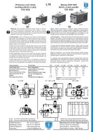
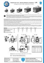
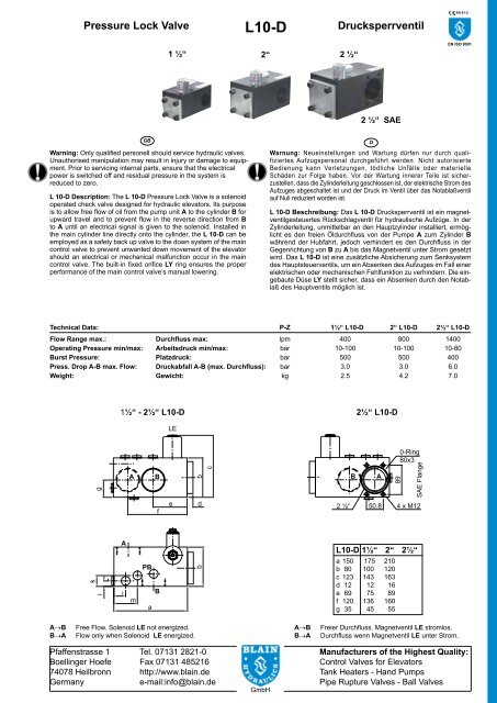
Pressure Lock Valve<br />
L 10-D Description: The L 10-D Pressure Lock Valve is a solenoid<br />
operated check valve designed for hydraulic elevators. Its purpose<br />
is to allow free flow of oil from the pump unit A to the cylinder B for<br />
upward travel and to prevent flow in the reverse direction from B<br />
to A until an electrical signal is given to the solenoid. Installed in<br />
the main cylinder line directly onto the cylinder, the L 10-D can be<br />
employed as a safety back up valve to the down system of the main<br />
control valve to prevent unwanted down movement of the elevator<br />
should an electrical or mechanical malfunction occur in the main<br />
control valve. The built-in fixed orifice LY ring ensures the proper<br />
performance of the main control valve’s manual lowering.<br />
k<br />
g<br />
l<br />
PB<br />
B<br />
<strong>L10</strong>-D<br />
2 ½“<br />
1½“ - 2½“ <strong>L10</strong>-D 2½“ <strong>L10</strong>-D<br />
A<br />
i<br />
A B<br />
A→B Free Flow. Solenoid LE not energized.<br />
B→A Flow only when Solenoid LE energized.<br />
m<br />
a<br />
f<br />
LE<br />
e<br />
b<br />
d<br />
b<br />
c<br />
B A<br />
89<br />
0-Ring<br />
80x3<br />
SAE Flange<br />
2 ½“ 50.8 4 x M12<br />
EN ISO 9001<br />
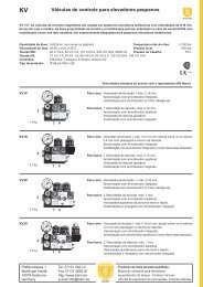
Technical Data: P-Z 1½“ <strong>L10</strong>-D 2“ <strong>L10</strong>-D 2½“ <strong>L10</strong>-D<br />
Flow Range max.: Durchfluss max: lpm 400 800 1400<br />
Operating Pressure min/max: Arbeitsdruck min/max: bar 10-100 10-100 10-80<br />
Burst Pressure: Platzdruck: bar 500 500 400<br />
Press. Drop A-B max. Flow: Druckabfall A-B (max. Durchfluss): bar 3.0 3.0 6.0<br />
Weight: Gewicht: kg 2.5 4.2 7.0<br />
Pfaffenstrasse 1 Tel. 07131 2821-0<br />
Boellinger Hoefe Fax 07131 485216<br />
74078 Heilbronn http://www.<strong>blain</strong>.de<br />
Germany e-mail:info@<strong>blain</strong>.de<br />
GB<br />
1 ½“ 2“<br />
Warning: Only qualified personell should service hydraulic valves.<br />
Unauthorised manipulation may result in injury or damage to equipment.<br />
Prior to servicing internal parts, ensure that the electrical<br />
power is switched off and residual pressure in the system is<br />
reduced to zero.<br />
GmbH<br />
Drucksperrventil<br />
2 ½“ SAE<br />
<strong>L10</strong>-D 1½“ 2“ 2½“<br />
a 150 175 210<br />
b 80 100 120<br />
c 123 143 163<br />
d 12 12 16<br />
e 69 75 89<br />
f 120 136 160<br />
g 35 45 55<br />
EN 81-2<br />
D<br />
Warnung: Neueinstellungen und Wartung dürfen nur durch qualifiziertes<br />
Aufzugspersonal durchgeführt werden. Nicht autorisierte<br />
Bedienung kann Verletzungen, tödliche Unfälle oder materielle<br />
Schäden zur Folge haben. Vor der Wartung innerer Teile ist sicherzustellen,<br />
dass die Zylinderleitung geschlossen ist, der elektrische Strom des<br />
Aufzuges abgeschaltet ist und der Druck im Ventil über das Notablaßventil<br />
auf Null reduziert worden ist.<br />
L 10-D Beschreibung: Das L 10-D Drucksperrventil ist ein magnetventilgesteuertes<br />
Rückschlagventil für hydraulische Aufzüge. In der<br />
Zylinderleitung, unmittelbar an den Hauptzylinder installiert, ermöglicht<br />
es den freien Öldurchfluss von der Pumpe A zum Zylinder B<br />
während der Hubfahrt, jedoch verhindert es den Durchfluss in der<br />
Gegenrichtung von B zu A bis das Magnetventil unter Strom gesetzt<br />
wird. Das L 10-D ist eine zusätzliche Absicherung zum Senksystem<br />
des Hauptsteuerventils, um ein Absenken des Aufzuges im Fall einer<br />
elektrischen oder mechanischen Fehlfunktion zu verhindern. Die eingebaute<br />
Düse LY stellt sicher, dass ein Absenken durch den Notablaß<br />
des Hauptventils möglich ist.<br />
A→B Freier Durchfluss. Magnetventil LE stromlos.<br />
B→A Durchfluss wenn Magnetventil LE unter Strom.<br />
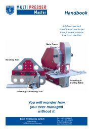
Manufacturers of the Highest Quality:<br />
Control Valves for Elevators<br />
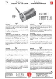
Tank Heaters - Hand Pumps<br />
Pipe Rupture Valves - Ball Valves
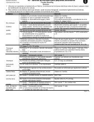
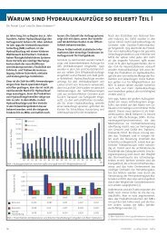
Hydraulic Circuit<br />
Hydraulikschema<br />
GB<br />
Rest Position: The condition of rest of the L 10 valve is with the<br />
solenoid LE de-energized and the main flow guide LV closed, preventing<br />
flow from cylinder to tank.<br />
Up Travel: During up travel with the pump running, oil flows through port<br />
A, through flow guide LV and out through port B to the main cylinder.<br />
Solenoid LE is not energized.<br />
Down Travel: For the elevator to travel downwards, in addition to the<br />
down solenoids C and D of the EV 100 control valve, solenoid LE of<br />
the Pressure Lock Valve is energized causing the flow guide LV to<br />
open and allowing oil from the cylinder to flow in the direction, port B<br />
to port A, of the Pressure Lock Valve and through the EV 100 control<br />
valve to tank.<br />
To slow down the elevator, solenoid C of the EV 100 is de-energized.<br />
Only upon completion of down levelling, is the solenoid LE of the L 10<br />
together with solenoid D of the EV 100 de-energized, causing both flow<br />
guides, X of the EV 100 and LV of the L 10 to close.<br />
No. Parts List<br />
LF Flange<br />
LFO 0-Ring- Flange<br />
LB Ball<br />
LVF Spring - Flow Guide<br />
LFG Flow Guide<br />
LVO Seal - Flow Guide<br />
LVB Body - Flow Guide<br />
LUO O-Ring - Flow Guide<br />
PB<br />
B<br />
Pressure Lock Valve <strong>L10</strong>-D Drucksperrventil<br />
MM Nut Solenoid<br />
M Standard Coil<br />
MD Emergency Dual Power Coil<br />
DR Tube Solenoid<br />
MO O-Ring Solenoid<br />
DF Spring Solenoid<br />
DN Needle Solenoid<br />
DK Core Solenoid<br />
DG Seat Housing (with screen)<br />
DS Seat Solenoid<br />
LY<br />
LV<br />
<strong>L10</strong>-D EV 100<br />
LE<br />
Nr. Benennung<br />
LF Flansch<br />
LFO O-Ring - Flansch<br />
LB Kugel<br />
LVF Feder - Hauptkolben<br />
LFG Kegel - Hauptkolben<br />
LVO Dichtung - Hauptkolben<br />
LVB Körper - Hauptkolben<br />
LUO O-Ring - Hauptkolben<br />
MM Mutter - Magnetventil<br />
M Magnetspule<br />
MD Notstromspule<br />
DR Rohr - Magnetventil<br />
MO 0-Ring Magnetventil<br />
DF Feder - Magnetventil<br />
DN Nadel Magnetventil<br />
DK Kern - Magnetventil<br />
DG Sitzhalter mit Sieb - Mag.<br />
DS Sitzscheibe - Magnetventil<br />
A Z<br />
Ruhezustand: In der Ruhestellung ist beim L 10 der Hauptkolben<br />
LV geschlossen und das Magnetventil LE stromlos, wodurch ein<br />
Öldurchfluss vom Zylinder zum Tank verhindert wird.<br />
Hubfahrt: Mit laufender Pumpe fliesst Öl durch Anschluss A über den<br />
Hauptkolben LV und durch Anschluss B zum Zylinder. Magnetventil<br />
LE steht nicht unter Strom.<br />
Senkfahrt: Damit der Aufzug abwärts fährt, muss das Magnetventil LE<br />
des L 10 Drucksperrventils zusätzlich zu den Magnetventilen C und<br />
D des EV 100 Ventils unter Strom gesetzt werden. Öl fliesst aus der<br />
Vorsteuerkammer des L 10 Hauptkolbens LV über Magnetventil LE.<br />
LV öffnet, wodurch ein Durchfluss vom Zylinder zum Tank über das L<br />
10 Richtung Anschluss B zu A sowie den EV 100 entsteht.<br />
Um den Aufzug zu verlangsamen, wird Magnetventil C des EV 100<br />
stromlos. Erst am Ende der Schleichfahrt wird das Magnetventil LE<br />
des L 10 Ventils zusammen mit Magnetventil D des Hauptsteuerventils<br />
stromlos, was das vollständige Schliessen der beiden Kolben, LV im<br />
L 10 und X im EV 100 Ventil, bewirkt.<br />
M Standard Coil Standard Spule<br />
MD Double Coil Doppel Spule<br />
Control Elements<br />
LV Check Valve<br />
LH Manual Lowering<br />
LE Solenoid<br />
LY Fixed Orifice<br />
Connections<br />
A Control Valve Connection<br />
B Cylinder Side Connection<br />
LVO LVB LUO<br />
2 mar 11 BLAIN HYDRAULICS Designers and Builders of High Quality Valves for Hydraulic Elevators Printed in Germany<br />
LFG<br />
PB<br />
LV<br />
D<br />
LE<br />
Steuerelemente<br />
LV Rückschlagventil<br />
LH Notablass<br />
LE Magnetventil<br />
LY Düse<br />
DR<br />
MM<br />
LVF<br />
Anschlüsse<br />
A Anschluss Steuerventil<br />
B Anschluss Zylinderseite<br />
DK<br />
DF<br />
DN<br />
DG<br />
MO<br />
LB<br />
DS<br />
LF<br />
LFO