Deckblatt ER32 short manual - Blemo
Deckblatt ER32 short manual - Blemo
Deckblatt ER32 short manual - Blemo

Create successful ePaper yourself
Turn your PDF publications into a flip-book with our unique Google optimized e-Paper software.
ENGLISH<br />
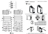
Control terminals<br />
Electrical characteristics<br />
Terminals Function Characteristics<br />
PLC External power<br />
supply input<br />
P24 Internal supply<br />
available<br />
DC Common 0 V common (2 terminals)<br />
FLA, FLB,<br />
FLC<br />
RY, RC<br />
F<br />
R<br />
RES<br />
36<br />
Configurable<br />
relay outputs<br />
Logic inputs<br />
+24 V input for possible external power supply for logic inputs<br />
Max. permissible voltage 50 V<br />
Short-circuit and overload protection:<br />
• 1 x DC 24 V supply (min. 21 V, max. 27 V), maximum current 50 mA.<br />
1 x relay logic output, 1 x "N/C" contact and 1 x "N/O" contact with common point<br />
Minimum switching capacity: 3 mA for DC 24 V<br />
Maximum switching capacity:<br />
• On resistive load (cos ϕ = 1): 1 A for AC 250 V or DC 30 V<br />
• On inductive load (cos ϕ = 0.4 and L/R = 7 ms): 0.5 A for AC 250 V or DC 30 V<br />
Max. response time: 7 ms ± 0.5 ms<br />
Electrical service life: 100,000 operations<br />
1 x relay logic output, 1 x "N/O" contact<br />
Minimum switching capacity: 3 mA for DC 24 V<br />
Maximum switching capacity:<br />
• On resistive load (cos ϕ = 1): 1 A for AC 250 V or DC 30 V<br />
• On inductive load (cos ϕ = 0.4 and L/R = 7 ms): 0.5 A for AC 250 V or DC 30 V<br />
Max. response time: 7 ms ± 0.5 ms<br />
Electrical service life: 100,000 operations<br />
3 x programmable logic inputs, DC 24 V, compatible with level 1 PLC, IEC 65A-68 standard<br />
Impedance: 3.5 kΩ<br />
Maximum voltage: 30 V<br />
Max. sampling time: 2 ms ± 0.5 ms<br />
Multiple assignment makes it possible to configure several functions on one input<br />
Positive logic (Source): State 0 if y 5 V or logic input not wired, state 1 if u 11 V<br />
Negative logic (Sink): State 0 if u 16 V or logic input not wired, state 1 if y 10 V<br />
FM Analog output 1 x switch-configurable voltage or current analog output:<br />
• Voltage analog output DC 0...10 V, minimum load impedance 470 Ω<br />
• Current analog output X-Y mA by programming X and Y from 0 to 20 mA,<br />
maximum load impedance 500 Ω<br />
Max. sampling time: 2 ms ± 0.5 ms<br />
Resolution: 10 bits<br />
Accuracy: ± 1 % for a temperature variation of 60°C<br />
Linearity: ± 0.2%<br />
PP Internal supply<br />
available<br />
Short-circuit and overload protection:<br />
• 1 x DC 10.5 V ± 5% supply for the reference potentiometer (1 to 10 kΩ),<br />
maximum current 10 mA<br />
VIA Analog inputs Switch-configurable voltage or current analog input:<br />
• Voltage analog input DC 0...10 V, impedance 30 kΩ (max. safe voltage 24 V)<br />
• Analog current input X-Y mA by programming X and Y from 0 to 20 mA, with<br />
impedance 242 Ω<br />
VIB<br />
Max. sampling time: 2 ms ± 0.5 ms<br />
Resolution: 11 bits<br />
Accuracy: ± 0.6% for a temperature variation of 60°C<br />
Linearity: ± 0.15% of the maximum value<br />
This analog input is also configurable as a logic input;<br />
Voltage analog input, configurable as an analog input or as a PTC probe input.<br />
Voltage analog input:<br />
• DC 0...10 V, impedance 30 kΩ (max. safe voltage 24 V)<br />
• Max. sampling time: 2 ms ± 0.5 ms<br />
• Resolution: 11 bits<br />
• Accuracy: ± 0.6% for a temperature variation of 60°C<br />
• Linearity: ± 0.15% of the maximum value<br />
PTC probe input:<br />
• 6 probes max. mounted in series<br />
• Nominal value < 1.5 kΩ<br />
• Trip resistance 3 kΩ, reset value 1.8 kΩ<br />
• Short-circuit protection < 50 Ω