Deckblatt ER32 short manual - Blemo
Deckblatt ER32 short manual - Blemo
Deckblatt ER32 short manual - Blemo

Create successful ePaper yourself
Turn your PDF publications into a flip-book with our unique Google optimized e-Paper software.
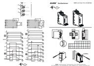
Variable speed drives for asynchronous motors<br />
Frequency inverter <strong>ER32</strong><br />
Short programming <strong>manual</strong><br />
R e t a i n f o r f u t u r e u s e!<br />
BLEMO ® Frequenzumrichter<br />
Siemensstraße 4<br />
D-63110 Rodgau<br />
Tel.: 06106 / 82 95-0<br />
Fax: 06106 / 82 95-20<br />
www.blemo.com<br />
info@blemo.com
ENGLISH<br />
Contents<br />
Important information______________________________________________________ 27<br />
Before you begin _________________________________________________________ 28<br />
Steps for setting up the drive________________________________________________ 29<br />
Preliminary recommendations _______________________________________________ 30<br />
Mounting _______________________________________________________________ 31<br />
Position of the capacitor charging LED ________________________________________ 32<br />
Wiring recommendations___________________________________________________ 33<br />
Power terminals__________________________________________________________ 34<br />
Control terminals _________________________________________________________ 35<br />
Connection diagrams______________________________________________________ 37<br />
Integrated display terminal _________________________________________________ 40<br />
Programming____________________________________________________________ 41<br />
Adjustment mode_________________________________________________________ 43<br />
Monitoring mode _________________________________________________________ 46<br />
26
Important information<br />
NOTICE<br />
Please read these instructions carefully and examine the device in order to familiarize yourself with it prior to<br />
installation, operation or maintenance. The specific messages below can appear in the documentation or on the<br />
device. They warn of potential dangers or draw your attention to information that can clarify or simplify a procedure.<br />
This symbol on a hazard or warning label indicates a potential risk of electrocution, which can<br />
result in bodily harm in the event of non-compliance with the accompanying instructions.<br />
This symbol indicates a safety hazard. It warns of the potential risk of physical injury.<br />
You must observe all safety instructions accompanied by this symbol in order to avoid situations that can result<br />
in serious physical injury or even death.<br />
IMPORTANT NOTE<br />
DANGER<br />
DANGER indicates a dangerous situation that will result in death, serious physical injury or equipment damage.<br />
WARNING<br />
WARNING indicates a dangerous situation that can result in death, serious physical injury or equipment<br />
damage.<br />
CAUTION<br />
CAUTION indicates a potentially dangerous situation that might possibly result in bodily harm or equipment<br />
damage.<br />
Electrical equipment must only be serviced by qualified personnel. <strong>ER32</strong> will not accept any responsibility for<br />
consequences associated with the use of this document. This document must not be used as a training guide for<br />
beginners.<br />
© 2007 BLEMO. All rights reserved.<br />
27<br />
ENGLISH
ENGLISH<br />
Before you begin<br />
Read and understand these instructions before performing any procedure on this drive.<br />
HAZARDOUS VOLTAGE<br />
28<br />
DANGER<br />
• Read and understand this <strong>manual</strong> before installing or operating the <strong>ER32</strong> drive. Installation, adjustment,<br />
repair, and maintenance must be performed by qualified personnel.<br />
• The user is responsible for compliance with all international and national electrical standards in force<br />
concerning protective grounding of all equipment.<br />
• Many parts of this variable speed drive, including the printed circuit boards, operate at the line voltage.<br />
DO NOT TOUCH.<br />
Use only electrically insulated tools.<br />
• DO NOT touch unshielded components or terminal strip screw connections with voltage present.<br />
• DO NOT <strong>short</strong> across terminals PA and PC or across the DC bus capacitors.<br />
• Install and close all the covers before applying power or starting and stopping the drive.<br />
• Before servicing the variable speed drive<br />
- Disconnect all power.<br />
- Place a "DO NOT TURN ON" label on the variable speed drive disconnect.<br />
- Lock the disconnect in the open position.<br />
• Disconnect all power including external control power that may be present before servicing the drive. Wait for<br />
the charging LED to go off. WAIT 10 MINUTES to allow the DC bus capacitors to discharge. Then follow the<br />
DC bus voltage measurement procedure on page 32 to verify that the DC voltage is less than 45 V. The drive<br />
LEDs are not accurate indicators of the absence of DC bus voltage.<br />
Failure to follow these instructions will result in death, serious physical injury or equipment damage.<br />
IMPROPER DRIVE OPERATION<br />
CAUTION<br />
• If the drive is not powered up for a long period, the performance of its electrolytic capacitors will be reduced.<br />
• If it is stopped for a prolonged period, turn the drive on every two years for at least 5 hours to restore the<br />
performance of the capacitors, then check its operation. It is recommended that the drive is not connected<br />
directly to the line voltage. The voltage should be increased gradually using an adjustable AC source.<br />
Failure to follow this instruction can result in bodily harm and/or equipment damage.
Steps for setting up the drive<br />
- 1 Take delivery of the drive<br />
• Check that the catalog number printed on the label is the same as that on the<br />
purchase order.<br />
Steps 1 to 4 must<br />
be performed with<br />
the power off.<br />
Tip:<br />
• Perform an auto-tuning operation to<br />
optimize performance.<br />
• Remove the Altivar from its packaging and check that it has not been damaged in<br />
transit.<br />
Note: Check that the wiring<br />
of the drive is compatible<br />
with its configuration.<br />
- 2 Check the line voltage<br />
• Check that the line voltage is compatible with the voltage range of the<br />
drive.<br />
- 3 Mount the drive (page 31)<br />
• Mount the drive in accordance with the instructions in this<br />
document.<br />
• Install any internal and external options.<br />
- 4 Wire the drive (page 33).<br />
• Connect the motor, ensuring that its connections correspond<br />
to the voltage.<br />
• Connect the line supply, after making sure that the power is<br />
off.<br />
• Connect the control.<br />
• Connect the speed reference.<br />
- 5 Power up without run command.<br />
- 6 Configure the AUF menu (page 45).<br />
• Speed variation range<br />
• Motor thermal protection<br />
• Motor frequency if not equal to 50 Hz.<br />
• Motor frequency if not equal to that of the drive.<br />
• If the motor's power rating differs from that of the<br />
drive, consult the CD-ROM supplied with the<br />
drive.<br />
- 7 Start.<br />
29<br />
ENGLISH
ENGLISH<br />
Preliminary recommendations<br />
Handling and storage<br />
To protect the drive prior to installation, handle and store the device in its packaging. Ensure that the ambient<br />
conditions are acceptable.<br />
DAMAGED PACKAGING<br />
Handling on installation<br />
Precautions<br />
30<br />
WARNING<br />
If the packaging appears damaged, it can be dangerous to open and handle it.<br />
Take precautions against all risks when performing this operation.<br />
Failure to follow this instruction can result in death, serious bodily harm or equipment damage.<br />
DAMAGED EQUIPMENT<br />
WARNING<br />
Do not operate or install any drive that appears damaged.<br />
Failure to follow this instruction can result in death, serious bodily harm or equipment damage.<br />
45°<br />
max.<br />
INCOMPATIBLE LINE VOLTAGE<br />
<strong>ER32</strong> drives up to ratings <strong>ER32</strong>-18.5/4K can be removed from their packaging and<br />
installed without a handling device.<br />
A hoist must be used for higher ratings; for this reason they are fitted with handling "lugs".<br />
The precautions described below must be observed.<br />
CAUTION<br />
Before turning on and configuring the drive, ensure that the line voltage is compatible with the line voltage range<br />
shown on the drive nameplate. Before turning on and configuring the drive, ensure that the line voltage is compatible<br />
with the line voltage range of the drive. The drive may be damaged if the line voltage is not compatible.<br />
Failure to follow this instruction can result in bodily harm and/or equipment damage.<br />
UNINTENDED EQUIPMENT OPERATION<br />
DANGER<br />
Before turning on or on exiting the configuration menus, check that the inputs assigned to the run command are<br />
deactivated (at state 0) since they can cause the motor to start immediately.<br />
Failure to follow these instructions will result in death, serious physical injury or equipment damage.
Mounting<br />
Mounting and temperature conditions<br />
≥ 50 mm<br />
≥ 50 mm<br />
(1.97 in.) (1.97 in.)<br />
Removing the protective cover<br />
Install the unit vertically, at ± 10°.<br />
Do not place it close to heating elements.<br />
Leave sufficient free space to ensure that the air required for cooling purposes can<br />
circulate from the bottom to the top of the unit.<br />
Free space in front of unit: 10 mm (0.4 in.) minimum<br />
3 types of mounting are possible<br />
Type A<br />
mounting:<br />
Type B<br />
mounting:<br />
Type C<br />
mounting:<br />
When IP20 protection is adequate, it is recommended that the protective cover on<br />
the top of the drive is removed as shown below.<br />
Free space u 50 mm (1.97 in.) on each side, with protective cover fitted<br />
u 50 mm u 50 mm<br />
(1.97 in.) (1.97 in.)<br />
Drives mounted side by side, with the protective cover removed (the degree of protection<br />
becomes IP20)<br />
Free space u 50 mm (1.97 in.) on each side, with protective cover removed (the degree of<br />
protection becomes IP20)<br />
u 50 mm u 50 mm<br />
(1.97 in.) (1.97 in.)<br />
Example <strong>ER32</strong>-22.0/4K<br />
These types of mounting are possible without derating up to 40°C at the factory-set switching frequenc y. For other<br />
ambient temperatures and switching frequencies, derating may be required (please consult our catalog).<br />
31<br />
ENGLISH
ENGLISH<br />
Position of the capacitor charging LED<br />
Before working on the drive, turn it off, wait until the capacitor charging LED has gone out, then measure the DC<br />
bus voltage.<br />
Procedure for measuring the DC bus voltage<br />
The DC bus voltage can exceed 1000 V DC. Use a properly rated voltage sensing device when performing this<br />
procedure. To measure the DC bus voltage:<br />
1 Disconnect the drive power supply.<br />
2 WAIT 10 MINUTES to allow the DC bus capacitors to discharge.<br />
3 Measure the voltage of the DC bus between the PA/+ and PC/- terminals to check whether the voltage is less<br />
than 45 V c.<br />
4 If the DC bus capacitors have not discharged completely, contact your local <strong>ER32</strong> representative (do not repair<br />
or operate the drive).<br />
32<br />
LED indicating<br />
that the DC bus<br />
is powered up<br />
HAZARDOUS VOLTAGE<br />
DANGER<br />
Read and understand the instructions on page 28 before performing this procedure.<br />
RUN<br />
PRG<br />
MON<br />
Failure to follow this instruction will result in death, serious physical injury or equipment damage.<br />
Loc<br />
Rem<br />
RUN STOP<br />
%<br />
Hz<br />
MODE<br />
ENT
Wiring recommendations<br />
Power<br />
The drive must be connected to the protective ground. To comply with current regulations concerning high leakage<br />
currents (above 3.5 mA), use at least a 10 mm² (AWG 6) protective conductor or 2 protective conductors with the<br />
same cross-section as the power section AC supply conductors.<br />
When upstream protection by means of a "residual current device" is required by the installation standards, a type<br />
A device should be used for single phase drives and type B for 3-phase drives. Choose a suitable model<br />
integrating:<br />
• HF current filtering<br />
DANGER<br />
HAZARDOUS VOLTAGE<br />
Ground equipment using the provided ground connecting point as shown in the figure below. The drive panel<br />
must be properly grounded before power is applied.<br />
Failure to follow these instructions will result in death or serious injury.<br />
variable<br />
speed drive<br />
variable<br />
speed drive<br />
variable<br />
speed drive<br />
• Check whether the resistance of the protective ground is one ohm or less.<br />
• If several drives need to be connected to protective ground, each one must be<br />
connected directly as indicated opposite.<br />
WARNING<br />
IMPROPER WIRING PRACTICES<br />
• The <strong>ER32</strong> drive will be damaged if input line voltage is applied to the output terminals (U/T1,V/T2,W/T3).<br />
• Check the power connections before energizing the <strong>ER32</strong> drive.<br />
• If replacing another drive, verify that all wiring connections to the <strong>ER32</strong> drive comply with all wiring<br />
instructions in this <strong>manual</strong>.<br />
Failure to follow these instructions can result in death or serious injury.<br />
• A time delay which prevents tripping caused by the load from stray capacitance on power-up. The time delay is<br />
not possible for 30 mA devices. In this case, choose devices with immunity against nuisance tripping, for<br />
example "residual current devices" with reinforced immunity from the s.i range.<br />
If the installation includes several drives, provide one "residual current device" per drive.<br />
WARNING<br />
INADEQUATE OVERCURRENT PROTECTION<br />
• Overcurrent protective devices must be properly coordinated.<br />
• The Canadian Electricity Code and the National Electrical Code require branch circuit protection. Use the<br />
fuses recommended on the drive nameplate to achieve published <strong>short</strong>-circuit current ratings.<br />
• Do not connect the drive to a power feeder whose <strong>short</strong>-circuit capacity exceeds the drive <strong>short</strong>-circuit<br />
current rating listed on the drive nameplate.<br />
Failure to follow these instructions can result in death or serious injury.<br />
33<br />
ENGLISH
ENGLISH<br />
Power terminals<br />
Access to terminals<br />
Open the cover as described below<br />
Functions of power terminals<br />
34<br />
Example <strong>ER32</strong>-1.5/4K Example <strong>ER32</strong>-22.0/4K<br />
Terminals Function<br />
Ground Protective ground connection terminal<br />
R/L1 - S/L2 - T/L3 Power section line supply<br />
U/T1 - V/T2 - W/T3 Outputs to the motor<br />
PO Do not use<br />
PA/+ DC bus + polarity<br />
PB Do not use<br />
PC/- DC bus - polarity<br />
The PO, PA/+, PB, and PC/- terminals can only be used to measure the voltage on the DC bus.<br />
Characteristics of power terminals<br />
<strong>ER32</strong>- Maximum wire size Tightening torque<br />
mm² AWG kcmils Nm (lb.in)<br />
0.75/4K to 5.5/4K 6 10 1.3 (11.5)<br />
7.5/4K to 11.0/4K 16 6 2.5 (22)<br />
15.0/4K to 18.5/4K 25 3 4.5 (40)<br />
22.0/4K to 45.0/4K 50 1/0 24 (212)<br />
55.0/4K to 75.0/4K 150 300 41 (360)
Control terminals<br />
The control card is the same for all power ratings.<br />
������<br />
���<br />
����<br />
��� ��� ��� �� ��� ��� ��� �� ��<br />
� � ��� ��<br />
����������������<br />
Maximum wire size: 2.5 mm²/AWG 14<br />
Tightening torque: 0.6 Nm (5.3 lb.in)<br />
�� ���<br />
� �<br />
� �<br />
�� ��� ��� ��<br />
WARNING<br />
Switch factory settings:<br />
SW1: SOURCE side<br />
(positive)<br />
FM: V side<br />
VIA: V side<br />
RISK OF IMPROPER OPERATION<br />
The logic input type selector switch is factory-set to the source position. Please consult the <strong>ER32</strong> drive<br />
Installation Manual before making any changes to the position of the switch.<br />
Failure to follow these instructions can result in death or serious injury.<br />
35<br />
ENGLISH
ENGLISH<br />
Control terminals<br />
Electrical characteristics<br />
Terminals Function Characteristics<br />
PLC External power<br />
supply input<br />
P24 Internal supply<br />
available<br />
DC Common 0 V common (2 terminals)<br />
FLA, FLB,<br />
FLC<br />
RY, RC<br />
F<br />
R<br />
RES<br />
36<br />
Configurable<br />
relay outputs<br />
Logic inputs<br />
+24 V input for possible external power supply for logic inputs<br />
Max. permissible voltage 50 V<br />
Short-circuit and overload protection:<br />
• 1 x DC 24 V supply (min. 21 V, max. 27 V), maximum current 50 mA.<br />
1 x relay logic output, 1 x "N/C" contact and 1 x "N/O" contact with common point<br />
Minimum switching capacity: 3 mA for DC 24 V<br />
Maximum switching capacity:<br />
• On resistive load (cos ϕ = 1): 1 A for AC 250 V or DC 30 V<br />
• On inductive load (cos ϕ = 0.4 and L/R = 7 ms): 0.5 A for AC 250 V or DC 30 V<br />
Max. response time: 7 ms ± 0.5 ms<br />
Electrical service life: 100,000 operations<br />
1 x relay logic output, 1 x "N/O" contact<br />
Minimum switching capacity: 3 mA for DC 24 V<br />
Maximum switching capacity:<br />
• On resistive load (cos ϕ = 1): 1 A for AC 250 V or DC 30 V<br />
• On inductive load (cos ϕ = 0.4 and L/R = 7 ms): 0.5 A for AC 250 V or DC 30 V<br />
Max. response time: 7 ms ± 0.5 ms<br />
Electrical service life: 100,000 operations<br />
3 x programmable logic inputs, DC 24 V, compatible with level 1 PLC, IEC 65A-68 standard<br />
Impedance: 3.5 kΩ<br />
Maximum voltage: 30 V<br />
Max. sampling time: 2 ms ± 0.5 ms<br />
Multiple assignment makes it possible to configure several functions on one input<br />
Positive logic (Source): State 0 if y 5 V or logic input not wired, state 1 if u 11 V<br />
Negative logic (Sink): State 0 if u 16 V or logic input not wired, state 1 if y 10 V<br />
FM Analog output 1 x switch-configurable voltage or current analog output:<br />
• Voltage analog output DC 0...10 V, minimum load impedance 470 Ω<br />
• Current analog output X-Y mA by programming X and Y from 0 to 20 mA,<br />
maximum load impedance 500 Ω<br />
Max. sampling time: 2 ms ± 0.5 ms<br />
Resolution: 10 bits<br />
Accuracy: ± 1 % for a temperature variation of 60°C<br />
Linearity: ± 0.2%<br />
PP Internal supply<br />
available<br />
Short-circuit and overload protection:<br />
• 1 x DC 10.5 V ± 5% supply for the reference potentiometer (1 to 10 kΩ),<br />
maximum current 10 mA<br />
VIA Analog inputs Switch-configurable voltage or current analog input:<br />
• Voltage analog input DC 0...10 V, impedance 30 kΩ (max. safe voltage 24 V)<br />
• Analog current input X-Y mA by programming X and Y from 0 to 20 mA, with<br />
impedance 242 Ω<br />
VIB<br />
Max. sampling time: 2 ms ± 0.5 ms<br />
Resolution: 11 bits<br />
Accuracy: ± 0.6% for a temperature variation of 60°C<br />
Linearity: ± 0.15% of the maximum value<br />
This analog input is also configurable as a logic input;<br />
Voltage analog input, configurable as an analog input or as a PTC probe input.<br />
Voltage analog input:<br />
• DC 0...10 V, impedance 30 kΩ (max. safe voltage 24 V)<br />
• Max. sampling time: 2 ms ± 0.5 ms<br />
• Resolution: 11 bits<br />
• Accuracy: ± 0.6% for a temperature variation of 60°C<br />
• Linearity: ± 0.15% of the maximum value<br />
PTC probe input:<br />
• 6 probes max. mounted in series<br />
• Nominal value < 1.5 kΩ<br />
• Trip resistance 3 kΩ, reset value 1.8 kΩ<br />
• Short-circuit protection < 50 Ω
Connection diagrams<br />
3-phase power supply<br />
A1<br />
Q1<br />
KM1<br />
1<br />
2<br />
1<br />
2<br />
U1<br />
L1<br />
U<br />
3<br />
4<br />
3<br />
4<br />
V1<br />
L2<br />
V<br />
M<br />
3<br />
5<br />
6<br />
5<br />
6<br />
W1<br />
L3<br />
W<br />
1 Q2 2 T1 1 Q3 S2<br />
2 S1<br />
3 4<br />
5 6<br />
FLA<br />
FLC<br />
(1)<br />
Note: All terminals are located at the bottom of the drive. Install interference suppressors on all inductive circuits<br />
near the drive or connected on the same circuit, such as relays, contactors, solenoid valves, fluorescent<br />
lighting, etc.<br />
Components that can be used in association with the Altivar: Consult our catalog<br />
Factory-set terminal functions<br />
FLB<br />
RY<br />
RC<br />
F<br />
R<br />
RES<br />
P24<br />
PP<br />
A1<br />
KM1<br />
FLA FLC 13 14<br />
VIA<br />
(2)<br />
CC<br />
CC<br />
PLC<br />
0…10 V<br />
KM1<br />
A1 A2<br />
VIB<br />
FM<br />
Voltage/current selection for<br />
analog I/O (FM and VIA)<br />
V (voltage)<br />
I (current)<br />
Switches (factory settings)<br />
V (voltage)<br />
I (current)<br />
FM VIA<br />
Selection of logic<br />
type<br />
Source<br />
(positive logic)<br />
PLC<br />
Sink<br />
(negative logic)<br />
FLA-FLB-FLC relay De-energized in the event of a fault or when the power supply is disconnected<br />
RY-RC relay Energized when the speed is greater than or equal to low speed (LL)<br />
F Forward (2-wire control)<br />
R Preset speed<br />
RES Clear fault (reset)<br />
VIA Speed reference 0-10 V<br />
VIB Not assigned<br />
FM Output frequency<br />
37<br />
ENGLISH
ENGLISH<br />
Connection diagrams<br />
Examples of recommended circuit diagrams<br />
Logic inputs according to the position of the logic type switch<br />
"Source" position "Sink" position "PLC" position with PLC transistor outputs<br />
Voltage analog inputs<br />
+ 10 V external<br />
38<br />
0 V<br />
F<br />
P24<br />
ATV 21<br />
<strong>ER32</strong> control terminals<br />
VIA<br />
Speed reference<br />
+ 10 V potentiometer<br />
2.2 to 10 kOhm<br />
CC<br />
24 V<br />
F<br />
CC<br />
ATV 21<br />
PLC<br />
CC<br />
PLC<br />
0 V<br />
F<br />
ATV 21<br />
24 V<br />
PLC<br />
CC<br />
PLC<br />
F<br />
ATV 21<br />
0 V 24 V
Connection diagrams<br />
1<br />
3 8 6 7 4<br />
Er32-0.75/4K to -18.5/4K<br />
8 8<br />
1<br />
5<br />
3 6 7 4<br />
<strong>ER32</strong>-22.0/4K to -75.0/4K<br />
2<br />
2<br />
5<br />
Connections to meet the requirements of EMC standards<br />
Principle<br />
b Grounds between the drive, motor and cable shielding must have<br />
"high-frequency" equipotentiality.<br />
b Use shielded cables with shielding connected to ground throughout<br />
360° at both ends for the motor cable and the contr ol-command<br />
cables. Conduit or metal ducting can be used for part of the shielding<br />
length provided that there is no break in the continuity of the ground<br />
connection.<br />
b Ensure maximum separation between the power supply cable (line supply)<br />
and the motor cable.<br />
Installation diagram for <strong>ER32</strong>-.../4K drives<br />
1 Steel plate to be mounted on the drive (grounded casing)<br />
2 UL Type 1/IP 21 <strong>ER32</strong> drive<br />
3 Unshielded power supply wires or cable<br />
4 Unshielded wires for the output of the fault relay contacts<br />
5 Attach and ground the shielding of cables 6 and 7 as close as possible<br />
to the drive:<br />
- Strip the shielding.<br />
- Attach the cable to the metal plate 1 by tightening the clamp on the<br />
stripped part of the shielding.<br />
The shielding must be clamped tightly enough to the metal plate to<br />
ensure good contact.<br />
6 Shielded cable for connecting the motor<br />
7 Shielded cable for connecting the control-command wiring.<br />
For applications requiring several conductors, use cables with a small<br />
cross-section (0.5 mm 2 ).<br />
For cables 6 and 7, the shielding must be grounded at both ends. The<br />
shielding must be continuous and intermediate terminals must be<br />
placed in EMC shielded metal boxes.<br />
8 Grounding screw. Use this screw for the motor cable on drives with<br />
lower power ratings, as the screw on the heatsink is inaccessible.<br />
Note: The HF equipotential ground connection between the drive, motor<br />
and cable shielding does not remove the need to connect the PE<br />
conductors (green-yellow) to the appropriate terminals on each<br />
unit.<br />
If using an additional EMC input filter, it should be mounted<br />
beneath the drive and connected directly to the line supply via an<br />
unshielded cable. Link 3 on the drive is then established via the<br />
filter output cable.<br />
39<br />
ENGLISH
ENGLISH<br />
Integrated display terminal<br />
Description of integrated display terminal<br />
The LEDs and keys on the integrated display terminal are illustrated below:<br />
40<br />
LED/Key Characteristics<br />
1 Display RUN LED Lights up when the run command is active<br />
Flashes when there is a speed reference<br />
2 Display PRG LED Lights up in programming mode (AUF... GrU)<br />
3 Display MON LED Lights up in monitoring mode<br />
4 Display unit 4 digits, 7 segments<br />
5 Display unit LED Numerical value displayed in hertz or percent<br />
6 Navigation arrows Depending on the mode:<br />
Navigate in menus<br />
Change a value<br />
Change the speed reference when the LED is lit (10)<br />
7 Arrow LED Lights up when the arrows are affecting the speed reference<br />
8 Loc/Rem LED Command and reference switching between terminals/com ↔ display terminal<br />
9 Mode Mode selection:<br />
• Default display mode<br />
• Adjustment mode<br />
• Monitoring mode<br />
Can also be used to go back to the previous menu<br />
10 Loc/Rem key Command and reference switching between terminals/com ↔ display terminal<br />
11 ENT Validation<br />
12 RUN LED Lights up when the <strong>ER32</strong> is in local run command mode<br />
13 RUN Local run command<br />
1<br />
2<br />
3<br />
6<br />
7<br />
12<br />
13<br />
RUN<br />
PRG<br />
MON<br />
Loc<br />
Rem<br />
RUN STOP<br />
14 STOP Stop/reset in the event of a fault<br />
%<br />
Hz<br />
MODE<br />
ENT<br />
4<br />
5<br />
8<br />
9<br />
10<br />
11<br />
14
Programming<br />
Access to different modes<br />
Use of the "MODE" key<br />
For more detailed information, consult the CD-ROM supplied with the drive.<br />
RUN<br />
Default<br />
display mode<br />
Default display mode • Active when the drive is switched on<br />
• Continuous display of a drive variable (current, speed, etc.), alarms and faults.<br />
Adjustment mode • Can be used to modify the drive parameters<br />
Monitoring mode • Can be used to control set frequencies, output current or voltage and information<br />
from the terminals<br />
Note:<br />
Access to menus<br />
Example in adjustment mode:<br />
MODE<br />
60.0 PROG AUF Fr-F<br />
MON<br />
AUF<br />
AUH<br />
---<br />
Gr.U<br />
Adjustment<br />
mode<br />
Monitoring<br />
mode<br />
MODE MODE<br />
Note: Press the "MODE" key to go back up to the next level;<br />
here, for example: Go back to Fr-F.<br />
41<br />
ENGLISH
ENGLISH<br />
Programming<br />
Access to parameters<br />
Example: Quick menu<br />
Note: Press the "MODE" key to go back to the previous menu.<br />
Examples: • From 9.9 to dEC<br />
• From dEC to AUF<br />
42<br />
AUF<br />
ENT<br />
AU1<br />
ACC<br />
dEC<br />
LL<br />
ENT<br />
10.1<br />
10<br />
9.9<br />
ENT<br />
Confirm value
Adjustment mode<br />
Description of menus<br />
The diagram below shows the various menus that can be accessed from the AUF quick menu:<br />
AUF menu: Fast startup menu providing access to the parameters of current applications and sufficient in the<br />
majority of cases<br />
AUH menu: Provides access to the last 5 parameters modified, in reverse chronological order (the last<br />
parameter modified appears first).<br />
AUF<br />
AUH<br />
AU1<br />
AU4<br />
CMOd<br />
FMOd<br />
FMSL<br />
FM<br />
tYP<br />
-<br />
-<br />
-<br />
-<br />
-<br />
Sr7<br />
F---<br />
GrU<br />
Consult the extended users guide for <strong>ER32</strong> drives.<br />
43<br />
ENGLISH
ENGLISH<br />
Adjustment mode<br />
The diagram below shows the various parameters that can be accessed from the AUF quick menu.<br />
44<br />
AUF<br />
ENT<br />
AU1 Automatic ramp times<br />
ACC<br />
dEC<br />
LL<br />
UL<br />
tHr<br />
FM<br />
Pt<br />
uL<br />
uLu<br />
Acceleration ramp times<br />
Deceleration ramp times<br />
Minimum motor frequency<br />
Maximum motor frequency<br />
Motor thermal protection<br />
Analog output scaling<br />
Motor control profile<br />
Nominal motor frequency<br />
Nominal motor voltage
Adjustment mode<br />
AUF menu<br />
The table below shows the various parameters that can be accessed from the AUF menu.<br />
Code Description Adjustment ranges Factory settings<br />
AU1 Automatic ramp times. 0 : Deactivated<br />
1 : Automatic acceleration and<br />
deceleration times<br />
2 : Automatic acceleration time only<br />
1<br />
ACC Acceleration time, in seconds 0.0 to 3200 10.0<br />
dEC Deceleration time, in seconds 0.0 to 3200 10.0<br />
LL Frequency lower limit (minimum motor<br />
frequency), in Hz.<br />
0.0 to UL 0.0<br />
UL Frequency upper limit (maximum motor<br />
frequency), in Hz.<br />
0.5 to 200.0 50.0<br />
tHr Motor electronic thermal protection level, as<br />
a % of the nominal output current indicated<br />
on the drive nameplate<br />
10 to 100 100<br />
FM Measurement adjustment (analog output<br />
scaling)<br />
- -<br />
Pt Selection of V/F control mode (motor<br />
control profile)<br />
0: V/F profile constant torque 1<br />
1: V/F profile variable torque<br />
2: Automatic torque "boost"<br />
3: Flux vector control<br />
4: Energy saving<br />
6: Permanent magnet synchronous<br />
motor<br />
25 to 500.0 50.0<br />
uL Base frequency (nominal motor frequency),<br />
in Hz<br />
uLu Voltage at base frequency (nominal motor<br />
voltage), in V<br />
50 to 660 (<strong>ER32</strong>-.../4K 400<br />
With the exception of ACC and dEC, the parameters cannot be modified while the drive is running.<br />
45<br />
ENGLISH
ENGLISH<br />
Monitoring mode<br />
Display of information relating to faults<br />
Display of fault code<br />
If the drive trips, an error code will be displayed indicating the cause. As trips are recorded, information about each<br />
can be displayed at any time in status control mode.<br />
The table below lists the various error codes and their description.<br />
46<br />
Error code Description<br />
nErr No error<br />
OC1-0C1P Overcurrent during acceleration<br />
OC2-0C2P Overvoltage during deceleration<br />
OC3-0C3P Overcurrent during operation at constant speed<br />
OCL Motor overcurrent during startup<br />
OCA Drive overcurrent during startup<br />
EPH1 An input phase error has occurred or the capacitor on the main<br />
circuit has discharged.<br />
EPH0 Output phase error<br />
OP1 Overvoltage during acceleration<br />
OP2 Overvoltage during deceleration<br />
OP3 Overvoltage during operation at constant speed<br />
OL1 Drive trip due to overload<br />
OL2 Motor trip due to overload<br />
OLr Dynamic braking records a trip due to overload<br />
OH Trip due to overheating or failure of thermal sensor<br />
E Emergency stop<br />
EEP1 Failure of EEPROM 1 (write error)<br />
EEP2 Failure of EEPROM 2 (initialization error) or power failure during<br />
parameterization of tYp<br />
EEP3 Failure of EEPROM 3 (read error)<br />
Err2 Drive RAM failure<br />
Err3 Drive ROM failure<br />
Err4 CPU 1 trip due to error<br />
Err5 Communication error<br />
Err7 Current detector error<br />
Err8 Option card error
Monitoring mode<br />
Error code Description<br />
UC Trip due to insufficient current<br />
UP1 Undervoltage trip<br />
0t Excessive torque trip<br />
EF2 Grounding error<br />
Etn1 Automatic adjustment error<br />
EtYP Drive type error<br />
OH2 External thermal input<br />
E-18 VIA cable break<br />
E-19 Communication error between CPUs<br />
E-20 V/F control error<br />
E-21 CPU 2 error<br />
SOUt Loss of synchronism during operation (for PM motors only)<br />
Note: Earlier trip records (trip record logs or trips that occurred in the past) can be retrieved.<br />
47<br />
ENGLISH