Electronic Transmission Control Introduction 1-10-03.qxd - GE39
Electronic Transmission Control Introduction 1-10-03.qxd - GE39
Electronic Transmission Control Introduction 1-10-03.qxd - GE39

Create successful ePaper yourself
Turn your PDF publications into a flip-book with our unique Google optimized e-Paper software.
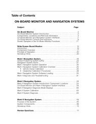
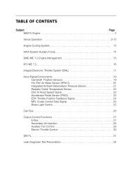
Table of Contents<br />
<strong>Electronic</strong> <strong>Transmission</strong> <strong>Control</strong><br />
Subject<br />
Page<br />
Purpose of the System ........................................................................ 4<br />
<strong>Transmission</strong> Versions and <strong>Control</strong> Systems ................................... 6<br />
<strong>Transmission</strong> Identification ................................................................. 8<br />
System Components ........................................................................... <strong>10</strong><br />
<strong>Transmission</strong> <strong>Control</strong> Module ................................................................ 11<br />
Speed Sensing ..................................................................................... 12<br />
<strong>Transmission</strong> Oil Temp Sensor .............................................................. 13<br />
Kickdown Switch/Circuit ....................................................................... 14<br />
Brake Switch ........................................................................................ 15<br />
<strong>Transmission</strong> Range Selector Switch .................................................... 16<br />
<strong>Transmission</strong> Program Switch ............................................................... 17<br />
Steptronic Components ........................................................................ 18<br />
Magnetic Valves .................................................................................... 19<br />
Pressure Regulating Solenoids .............................................................. 20<br />
Mechatronics Module ............................................................................ 21<br />
Instrument Cluster ................................................................................. 22<br />
<strong>Transmission</strong> Features and Principles of Operation ........................ 24<br />
Adaptive Hydraulic Pressure <strong>Control</strong> ......................................................24<br />
Downshift Protection.............................................................................. 25<br />
Reverse Lockout ................................................................................... 25<br />
Engine Warm Up Cycle ......................................................................... 25<br />
ASC/DSC Shift Intervention .................................................................. 25<br />
Torque Reduction ................................................................................. 25<br />
Emergency Program ............................................................................. 26<br />
A/C Compressor Load Sensing ............................................................ 27<br />
Shift Lock ............................................................................................. 27<br />
Torque Converter Clutch ....................................................................... 28<br />
Shift Solenoid <strong>Control</strong> ........................................................................... 30<br />
Pressure Regulation .............................................................................. 31<br />
Shift Programs .......................................................................................32<br />
Steptronic ..............................................................................................34<br />
Initial Print Date: 1/15/03<br />
Revision Date:
Model: All with BMW Automatic <strong>Transmission</strong><br />
Production: All<br />
Objectives:<br />
After completion of this module you will be able to:<br />
• Identify BMW EH Automatic <strong>Transmission</strong>s.<br />
• Identify <strong>Electronic</strong> <strong>Transmission</strong> <strong>Control</strong> Components<br />
• Understand <strong>Electronic</strong> <strong>Transmission</strong> Operation<br />
• Diagnose <strong>Transmission</strong> related faults using the DISplus or GT-1<br />
• Understand service items and special tools.<br />
3<br />
<strong>Electronic</strong> <strong>Transmission</strong> <strong>Control</strong>
Purpose of the System<br />
<strong>Electronic</strong>ally controlled transmissions were introduced on BMW products in 1986 on 5 and<br />
7 series vehicles. Currently EH (Electro-hydraulic) transmissions are offered on almost every<br />
production model (Except E46 M3 and E39 M5). EH transmissions offer the following benefits<br />
the to driver:<br />
• Increased driving safety by reducing fatigue. All shifts are automatic as opposed to<br />
manual transmissions which require more driver interaction.<br />
• Increased fuel economy through use of lock up torque converter.<br />
• Increased fuel economy through optimized shift points.<br />
• Improved shift comfort by use of “Overlap Shift” technology (ZF).<br />
• More available features through the use of CAN bus technology.<br />
4<br />
<strong>Electronic</strong> <strong>Transmission</strong> <strong>Control</strong>
The EH <strong>Control</strong> System is designed to work in conjunction with the engine electronics for<br />
precise shift control. The TCM receives information on engine RPM, load and throttle position<br />
to provide optimum shift points to maximize fuel economy and driver comfort.<br />
The function of an EGS System is to:<br />
• Monitor all operating conditions through input signals<br />
• Continually assess operating conditions by processing input data and select the<br />
appropriate operating program for current conditions.<br />
• Activate transmission system components and to communicate with other drivetrain<br />
control systems.<br />
• Respond to driver selected driving program (Economy, Sport or Manual).<br />
In addition to providing shift control, the TCM also adapts to changing conditions within the<br />
transmission by monitoring slip ratios and modifying line pressure. This increases the life of<br />
the transmission and reduces maintenance and adjustments. The TCM controls the operation<br />
of the Lock-Up Torque Converter which further increases economy.<br />
On current models, the TCM also has the capability of adapting to driver habits and<br />
responds to changing environmental conditions. Items such as rate of throttle input and<br />
kickdown requests are monitored to select the most appropriate shift program.<br />
The EGS system is also required to maintain occupant safety, safeguard drivetrain damage,<br />
improve vehicle emissions and operate in failsafe mode when a malfunction occurs.<br />
5<br />
<strong>Electronic</strong> <strong>Transmission</strong> <strong>Control</strong>
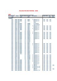
<strong>Transmission</strong> Version and <strong>Control</strong> Systems<br />
Each BMW Electro-hydraulic transmission has a corresponding control system. They are<br />
designated “GS” which stands for <strong>Transmission</strong> <strong>Control</strong>. This acronym is from the German<br />
words Getriebe Steurung. Each transmission can have more than one control system, this<br />
depends upon application (model year, series etc.). Below is a listing of ZF control systems<br />
used on BMW vehicles, Hydramatic control systems are shown on the opposing page.<br />
ZF <strong>Control</strong> Systems<br />
<strong>Transmission</strong><br />
BMW ID #<br />
Manufacturer<br />
ID<br />
4HP22 (EH) 4HP22 (EH) 86 535i<br />
86 635i<br />
86 735i<br />
Model/Year<br />
<strong>Control</strong> System Engine<br />
GS 1.2X<br />
GS 1.2X<br />
GS 1.2X<br />
M30<br />
M30<br />
M30<br />
4HP24 (EH) 4HP24 (EH) 88-9/91 750iL (E32)<br />
92-94 750iL (E32)<br />
90-94 850i/Ci (E31)<br />
GS 1.27<br />
GS 1.29<br />
GS 1.29<br />
M70<br />
M70<br />
M70<br />
A5S3<strong>10</strong>Z 5HP18 93 530i/iT (E34)<br />
94 530i/iT (E34)<br />
95 M3 (E36)<br />
96-99 M3 (E36)<br />
GS 7.3<br />
GS 7.32<br />
GS 7.11<br />
GS 8.32<br />
M60<br />
M60<br />
S50 (US)<br />
S52<br />
A5S325Z 5HP19 00 323i/Ci/CiC (3/00-8/00)<br />
01 323iT (from 4/01)<br />
01-02 325i/Ci/CiC from 9/00<br />
00-01 330i/Ci/CiC from 6/00<br />
01- 525 from 3/01<br />
01- 530 from 3/01<br />
03 Z4 (E85) 2.5i and 3.0i<br />
GS 8.60<br />
GS 8.60<br />
GS 8.60.4<br />
GS 8.60.4<br />
GS 8.60.4<br />
GS 8.60.4<br />
GS 8.60.4<br />
M52 TU<br />
M52 TU<br />
M54<br />
M54<br />
M54<br />
M54<br />
M54<br />
A5S440Z 5HP24 97 840Ci (E31) from 9/96<br />
97 540i (E39) 1/97-8/97<br />
97 740i/iL (1/97 - 4/97)<br />
97 740i/iL (5/97-8/97)<br />
98-03 540i<br />
98-01 740i/iL<br />
00- X5 4.4i<br />
GS 8.55 (CAN index 50)<br />
GS 8.55 (CAN index 50)<br />
GS 8.55 (CAN index 50)<br />
GS 8.55 (CAN index 60)<br />
GS 8.60.2 (CAN index 60)<br />
GS 8.60.2 (CAN index 60)<br />
GS 8.60.2<br />
M62<br />
M62<br />
M62<br />
M62<br />
M62, M62 TU 99-02<br />
M62, M62 TU 99-01<br />
M62TU<br />
A5S560Z 5HP30 93-94 740i/iL (E32)<br />
93 540i (E34)<br />
94-95 540i (E34)<br />
94-95 840Ci (E31)<br />
95 740i/iL (E38)<br />
95-01 750iL (E38)<br />
96-97 740i/iL ( -1/97)<br />
96 840Ci (E31)<br />
95-97 850Ci<br />
GS 9.2<br />
GS 9.2<br />
GS 9.22<br />
GS 9.22<br />
GS 9.22<br />
GS 9.22.1<br />
GS 9.22.1<br />
GS 9.22.1<br />
GS 9.22.1<br />
M60<br />
M60<br />
M60<br />
M60<br />
M60<br />
M73/M73TU<br />
M62<br />
M62<br />
M73<br />
GA6HP26Z<br />
GA6HP26Z<br />
GA6HP26Z<br />
02- 745Li (E65/E66)<br />
03- 760Li (E66)<br />
GS 19<br />
GS 19<br />
N62<br />
N73<br />
6<br />
<strong>Electronic</strong> <strong>Transmission</strong> <strong>Control</strong>
Hydramatic <strong>Control</strong> Systems<br />
<strong>Transmission</strong><br />
BMW ID #<br />
Manufacturer<br />
ID #<br />
Model/Year<br />
<strong>Control</strong><br />
System<br />
Engine<br />
A4S3<strong>10</strong>R<br />
(THM-R1)<br />
4L30-E(A4S3<strong>10</strong>R) >>><br />
90-92 525i (E34)<br />
93-95 525i (E34)<br />
92 325i,is,ic (E36)<br />
93-95325i,is,ic (E36)<br />
92-95 318ti (E36)<br />
GS 4.14<br />
GS 4.16<br />
GS 4.14<br />
GS 4.16<br />
GS 4.14 & GS 4.16<br />
M50<br />
M50 TU<br />
M50<br />
M50 TU<br />
M42<br />
A4S270R 4L30-E(A4S270R) >>> 96-98 328i (is,ic -97)<br />
96-98 318i (is,ic-97)<br />
96-98 318ti (E36/5)<br />
96-98 Z3 1.9 (E36/7)<br />
96-98 Z3 2.8<br />
97-98 528i (E39)<br />
GS 8.34<br />
GS 8.34<br />
GS 8.34<br />
GS 8.34<br />
GS 8.34<br />
GS 8.34<br />
M52<br />
M44<br />
M44<br />
M44<br />
M52<br />
M52<br />
A5S360R (GM5) 5L40-E (A5S360R) >> 99-00 323i/Ci (7/98-3/00)<br />
99-00 328i/Ci (6/98-5/00)<br />
99-00 528i (E39) 9/99-8/00<br />
99-00 Z3 (E36/7) 2.3/2.8<br />
GS 20<br />
GS 20<br />
GS 20<br />
GS 20<br />
M52 TU<br />
M52 TU<br />
M52 TU<br />
M52 TU<br />
A5S390R (GM5)<br />
5L40-E (A5S390R) >> 00-03 X5 3.0i (4/00 - )<br />
01 325iT (8/00-3/01)<br />
GS 20<br />
GS 20<br />
01-03 325xi/xiT & 330Xi (- GS 20<br />
8/00)<br />
01 525i/iT (9/00-3/01)<br />
01 530i (9/00-3/01)<br />
GS 20<br />
GS 20<br />
GS 20<br />
01-02 Z3 2.5/3.0 (6/00- )<br />
M54<br />
M54<br />
M54<br />
M54<br />
M54<br />
M54<br />
GS 20 TCM (Siemens)<br />
7<br />
<strong>Electronic</strong> <strong>Transmission</strong> <strong>Control</strong>
<strong>Transmission</strong> Identification<br />
BMW automatic transmission are manufactured by two suppliers for the US market:<br />
• Zahnradfabrik Friedrichshafen: Commonly referred to as ZF. ZF manufactures both<br />
manual as well as automatic transmissions.<br />
• GM Powertrain - Hydramatic: Hydramatic is a manufacturing division of General<br />
Motors located in Strasbourg, France. Hydramatic supplies automatic transmissions<br />
to BMW for four and six-cylinder vehicles.<br />
BMW has developed an internal numbering system for their transmissions for ordering<br />
parts, information research and identification. Also, each transmission manufacturer uses<br />
an internal identification system. Here is a breakdown of these identification codes:<br />
BMW Identification Code Breakdown<br />
A = Automatic<br />
S= Standard<br />
Number of Gears<br />
A5S 440Z<br />
Overdrive Ratio<br />
S = Top Gear Overdrive<br />
D = Top Gear Direct Drive<br />
Manufacturer<br />
Z = ZF<br />
R = Hydramatic<br />
G = Getrag<br />
Maximum Input Torque Rating in Nm.<br />
HP = Hydraulic Planetary<br />
(automatic)<br />
ZF Identification Code Breakdown<br />
Number of Gears<br />
ZF Internal Designation<br />
5HP 24<br />
Hydramatic <strong>Transmission</strong>s have internal designations , however they are not used often.<br />
The internal code for the A4S3<strong>10</strong>/270R is 4L30-E and the A5S360/390R is 5L40-E.<br />
8<br />
<strong>Electronic</strong> <strong>Transmission</strong> <strong>Control</strong>
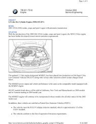
<strong>Transmission</strong> ID Tag Location<br />
In order to identify BMW transmissions there are identification tags located externally on the<br />
transmission case. The tag contains information such as Manufacturer, Serial number,<br />
transmission type etc. This information is needed when ordering parts, referencing bulletins<br />
and calling for technical assistance.<br />
• ZF - Tag is Located on -<br />
1. Right hand side (passenger side)<br />
of transmission case.<br />
(5HP30 and 5HP18)<br />
2. Left hand side (drivers side) of<br />
transmission case.<br />
(6HP26Z, 5HP24 and all 4HP)<br />
3. Rear under output shaft. (5HP19)<br />
ID Tag Location 5HP19<br />
ID Tag Location 5HP24<br />
Typical ZF Tag<br />
• GM - Located on left hand side<br />
(drivers side) of transmission<br />
case.<br />
GM ID Tag (GM 5)<br />
Hydramatic ID Tag Location (GM5)<br />
9<br />
<strong>Electronic</strong> <strong>Transmission</strong> <strong>Control</strong>
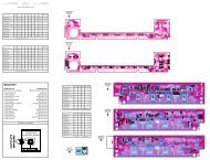
System Components (Electrical)<br />
A5S 440Z<br />
GS 8.55<br />
GS 8.60.2<br />
RANGE DISPLAY<br />
PROGRAM DISPLAY<br />
ECM<br />
Main<br />
Relay<br />
87a<br />
+<br />
RANGE<br />
M62<br />
DIAGNOSIS -- PROGRAMMING<br />
GT-1<br />
SHIFT LOCK<br />
DISplus<br />
MV 3<br />
MANUAL GATE<br />
MV 2<br />
STEPTRONIC<br />
CAN<br />
TERMINATING<br />
RESISTOR<br />
PROG SWITCH<br />
E38-E31*<br />
WITHOUT<br />
STEPTRONIC<br />
+<br />
HALL EFFECT<br />
BRAKE PEDAL<br />
SENSOR<br />
KICK DOWN<br />
SWITCH<br />
8.55 (CAN 60)<br />
8,60.2<br />
MV 1<br />
EDS 5<br />
EDS 2<br />
EDS 3<br />
EDS 4<br />
EDS 1<br />
ASC<br />
DME<br />
CAN<br />
WHEEL<br />
SPEED<br />
SIGNALS<br />
POWER<br />
OIL TEMP<br />
INPUT SPEED<br />
OUTPUT SPEED<br />
VALVE BODY<br />
<strong>10</strong><br />
<strong>Electronic</strong> <strong>Transmission</strong> <strong>Control</strong>
<strong>Transmission</strong> <strong>Control</strong> Module<br />
The TCM receives inputs, processes information and actuates the output elements to provide<br />
optimal shift points. The TCM is programmed for maximum shift comfort and fuel<br />
economy. The TCM on most BMW vehicles is located in the E-Box next to the ECM (DME).<br />
Always refer to the proper ETM for TCM location.<br />
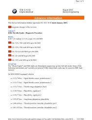
There are several types of TCM housings:<br />
• 35 Pin TCM (TCU) - used on the 4HP transmissions<br />
• 55 Pin TCM - used on the A4S3<strong>10</strong>R (THM-R1)<br />
• 88 Pin TCM - used on all others up to 98<br />
• 134 Pin TCM - used on all BMW transmission from the 99 model year.<br />
(Note- the 134 pin TCM was introduced on the 98 Models equipped with the<br />
A5S440Z).<br />
The 134 Pin TCM is also referred to as SKE (Standard Shell Construction). The SKE housing<br />
uses 5 separate connectors. On transmission applications only three connectors 1, 3<br />
and 4) are used. Connectors 2 and 5 are blank and are NOT used. The connectors are blue<br />
in color to avoid confusion with the ECM (DME) connectors which are black.<br />
!34 Pin control modules are supplied by Bosch for ZF transmissions and Siemens for<br />
Hydramatic transmissions. Bosch and Siemens control modules are NOT interchangeable.<br />
134 Pin TCM<br />
with SKE housing<br />
Connectors 1 2 3 4 5<br />
55 Pin TCM 88 Pin TCM<br />
11<br />
<strong>Electronic</strong> <strong>Transmission</strong> <strong>Control</strong>
Turbine Speed Sensor<br />
The Turbine Speed Sensor is used to provide input (turbine) shaft speed information to the<br />
TCM (EGS). The input shaft speed signal is used in conjunction with the output shaft speed<br />
signal to determine gear range and slip time information for processing in the TCM. Not all<br />
BMW transmissions use a turbine speed sensor. Some TCM’s use the TD (engine speed)<br />
signal to determine input shaft speed. All transmissions with the exception of the A5S325Z<br />
use an inductive type sensor which generates an AC analog signal. The A5S325Z currently<br />
uses a Hall Effect Turbine Speed Sensor which will send a digital square wave signal to the<br />
TCM.<br />
4HP22/24 (EH), A4S3<strong>10</strong>/270R: These transmissions do not use a Turbine Speed Sensor.<br />
The TD signal is used to determine input shaft speed. The TD signal is an output signal of<br />
the DME control unit.<br />
A5S3<strong>10</strong>Z, A5S325Z, A5S440Z, A5S560Z, A5S360/390R: These transmission use a turbine<br />
speed sensor. The TD signal is also used with the turbine speed signal to allow the<br />
TCM to monitor Torque Converter Clutch operation. The TCM can control torque converter<br />
clutch slippage and also monitor for faults.<br />
Output Shaft Speed Sensor<br />
The Output Shaft Speed Sensor is used to provide output shaft speed information to the<br />
TCM. The output shaft speed signal is used in conjunction with the turbine speed signal to<br />
provide the TCM with information on gear ranges and slip times.<br />
All BMW electronic transmissions have an output shaft speed sensor. The output shaft<br />
speed sensor is an inductive type which will generate an AC analog signal to the TCM. The<br />
frequency and amplitude of the signal will increase as output shaft speed increases. The<br />
exact location of the output shaft speed sensor varies by transmission model.<br />
Output<br />
Speed Signal<br />
Turbine Speed Signal<br />
Typical Speed Sensor Signal<br />
DME<br />
12<br />
<strong>Electronic</strong> <strong>Transmission</strong> <strong>Control</strong><br />
TCM<br />
GETRIEBESTEUERUNG
<strong>Transmission</strong> Oil Temp Sensor<br />
The TCM is provided with transmission oil temperature information via a temperature sensor.<br />
On most BMW transmissions, the sensor is an NTC element which is part of the transmission<br />
internal wiring harness.<br />
4HP22/24 (EH): These transmissions do not use a transmission oil temperature sensor.<br />
There are no transmission oil temperature influenced features on the 4HP transmissions.<br />
All Except A5S360/390R, GA6HP26Z: The transmission fluid temp sensor is part of the<br />
transmission internal wiring harness. On these transmissions, the sensor cannot be<br />
replaced separately. The harness must be replaced.<br />
A5S360/390R transmission: the sensor is a separate, replaceable sensor that can be<br />
unplugged from the harness.<br />
GA6HP26Z: the sensor is located in the Mechatronics Module, which is located inside of<br />
the transmission.<br />
Note: The Mechatronics Module is not currently serviceable at this time. Contact<br />
the BMW Technical Hotline in the event of a failure. Do not attempt any repair or<br />
replacement of the Mechatronics Module.<br />
The transmission oil temperature information is used to:<br />
• Initiate the Warm Up Program<br />
• To inhibit TCC operation until<br />
a specified temperature has<br />
been reached.<br />
TCM<br />
• For determining fluid level<br />
when used with diagnostic<br />
equipment.<br />
The transmission oil temperature<br />
sensor is connected to the TCM via a<br />
5 Volt reference and a circuit ground.<br />
As transmission oil temperature<br />
increases, the circuit resistance and<br />
voltage decrease proportionately.<br />
NTC Temp Sensor<br />
13<br />
<strong>Electronic</strong> <strong>Transmission</strong> <strong>Control</strong>
Kickdown Switch<br />
The TCM receives a kickdown request via one of two possible methods:<br />
• The kickdown signal is a direct ground input to the TCM. The kickdown input is<br />
provided by a kickdown switch located under the accelerator pedal.<br />
This method is used on most BMW vehicles without electronic throttle control systems<br />
(except M52TU with MDK).<br />
Kickdown<br />
Switch<br />
• The kickdown request is provided by the ECM (DME) via the CAN bus. The kick<br />
down request originates from the PWG. There is no separate switch in the PWG.<br />
When the PWG voltage reaches approximately 4.5 volts, the ECM will process a<br />
kickdown request to the TCM via CAN. The PWG contains a kickdown detent to<br />
simulate the feel of a kickdown switch.<br />
This method is used on the M62TU, M54, M73, M73TU, N73 and N62 engines.<br />
DME<br />
Kickdown signal to TCM<br />
via CAN<br />
TCM<br />
D.C. Analog Signal from<br />
PWG to DME<br />
.1 to 4.9 Volts<br />
PWG<br />
CAN bus<br />
Twisted Pair Wiring<br />
14<br />
<strong>Electronic</strong> <strong>Transmission</strong> <strong>Control</strong>
Brake Switch<br />
The brake switch is located on the brake pedal linkage. The brake switch signal is an input<br />
to the TCM which is used for:<br />
• De-activation of the shift lock solenoid. When the ignition key is turned to KL15 the<br />
shift lock is active. The shift lock solenoid is de-activated when the brakes are<br />
applied.<br />
• De-activate the Torque Converter . The TCC is deactivated whenever the brake is<br />
applied. (only on Hydramatic <strong>Transmission</strong>s ).<br />
There are two types of brake switches used on BMW vehicles:<br />
• On early vehicles such as E32, E34, E36, E24, E28 and E31 the brake switch is a<br />
double-contact mechanical switch. There is a brake light circuit and a brake test<br />
circuit. The brake test circuit is used for a plausibility check to indicate faults within<br />
the brake light circuit.<br />
• On the E38, E39, E46, E65/66, E85 and E53 the brake switch is a hall effect type<br />
switch. The electronic switch is also monitored for faults and plausibility.<br />
15<br />
<strong>Electronic</strong> <strong>Transmission</strong> <strong>Control</strong>
<strong>Transmission</strong> Range Selector Switch<br />
The range selector switch is an input to the TCM. The input is used by the TCM to determine<br />
the position of the manual valve. The range switch uses the familiar “coded input” signal<br />
to determine selector lever position. On all transmissions except the A5S360/390R, the<br />
range switch uses a 4 wire configuration to determine 7 range selector positions. The<br />
A5S360/390R uses a five wire arrangement.<br />
Most range switches are located on the transmission<br />
case with some exceptions. The E36 with the<br />
A4S270/3<strong>10</strong>R the range switch is located is the center<br />
console on the selector lever assembly. The E39<br />
with A4S270R the range switch is located on the<br />
transmission case and is adjustable. The range selector<br />
switch on the A5S360/390R is located inside the<br />
transmission housing. GA6HP26Z is part of the<br />
Mechatronics Module.<br />
Range Switch A5S440Z<br />
The range switch can be checked by using “Status<br />
Requests” in the DISplus or GT-1.<br />
A multimeter or an oscilloscope can also be used to check the range switch. If the reading<br />
on “Status Requests” does not match the actual selector lever position, there will be<br />
various transmission malfunctions.<br />
Always refer to the proper ETM when diagnosing the range selector switch. Use the switch<br />
logic chart to diagnose faults in the switch.<br />
In the example below, the range switch is in neutral. Using the logic chart, switches L1, L2<br />
and L3 are closed providing B+ voltage to the corresponding pins of the TCM. Switch L4<br />
is open and no voltage is sent to the TCM. Malfunctions in the range switch or wiring can<br />
cause various shifting complaints and possible No-Start complaints.<br />
Switch<br />
Logic<br />
Chart<br />
16<br />
<strong>Electronic</strong> <strong>Transmission</strong> <strong>Control</strong>
<strong>Transmission</strong> Program Switch<br />
The transmission program switch is used to switch between various operating modes of<br />
the transmission. The normal default mode of the TCM is Economy which is indicated in<br />
the program display as “E”. Economy mode allows the transmission to operate in the most<br />
efficient mode. Shift priorities are for maximum economy and shift comfort. On some vehicles<br />
the program switch is designated “A” for economy mode. Program switches come in<br />
2 or 3 position configurations. Early vehicles with the 4HP (Early E7) used a rotary program<br />
switch.<br />
The TCM can also be switched to “Manual Mode” which on some vehicles is designated<br />
“Winter Mode”. Manual mode is used to start the vehicle off in a higher gear when encountering<br />
slippery conditions. The program display will indicate “M” (manual) or an asterisk<br />
symbol for “Winter Mode”.<br />
Sport Mode is the third operating mode that is available. Sport mode allows for a slightly<br />
delayed and more aggressive shift. Sport mode is obtained a number of ways. On vehicles<br />
with 2 position program switches, moving the selector lever out of drive to 4,3, or 2<br />
with the program switch in Economy will allow Sport mode. On vehicles with 3 position program<br />
switches, Sport mode can be obtained by switching to “S”.<br />
E38 Selector Lever with 2<br />
Position Program Switch<br />
3 Position<br />
Program<br />
Switch<br />
17<br />
<strong>Electronic</strong> <strong>Transmission</strong> <strong>Control</strong>
Steptronic Components<br />
The Steptronic system uses additional components not found on a conventional system.<br />
These components consist of a manual switch and an Up/Down microswitch. Otherwise,<br />
the Steptronic system uses the same transmission and TCM.<br />
The TCM monitors the Steptronic shifter position from P through D via the conventional<br />
range selector switch located on the transmission. The Range Selector Switch provides<br />
positions P through D to the TCM because the automatic gate of the shifter only travels<br />
through these positions.<br />
When the Steptronic Shifter is moved to the left 15 degrees into the manual gate, the TCM<br />
receives a ground input from the manual gate switch. The ground signal is provided to the<br />
TCM through the <strong>Transmission</strong> Position Indicator. The transmission position indicator also<br />
provides range position signaling to the range position indicator in the shift console.<br />
Steptronic was introduced on the E31 850Ci (<strong>10</strong>/94) and the 840Ci (1/96). Steptronic was<br />
subsequently introduced into the E38, E39, E46, E36/7 and the E53.<br />
The Steptronic system can be diagnosed through “Status Requests” with the DISplus or<br />
GT-1.<br />
Refer to TRI Bulletin B 24 75 96 for more information on Steptronic.<br />
From 2002 model year the Steptronic shifter<br />
has changed slightly. Downshifts are now<br />
achieved by moving the selector lever forward<br />
and upshifts are now rearward.<br />
Steptronic<br />
Up/Down<br />
Shift Switch<br />
<strong>Transmission</strong><br />
Position<br />
Indicator<br />
(up to 2001 MY)<br />
TCM<br />
Manual<br />
Switch<br />
Manual<br />
Mode<br />
Upshift<br />
18<br />
<strong>Electronic</strong> <strong>Transmission</strong> <strong>Control</strong><br />
Down<br />
Shift
Magnetic Valves<br />
Magnetic Valves (MV) are used to electronically control hydraulic fluid flow to the various<br />
shift elements within the transmission. Magnetic valves are located on the valvebody and<br />
replaceable as separate components. In ZF transmissions, MV valves are designated MV1,<br />
MV2, MV3 etc. In Hydramatic transmissions, they are designated Shift Valve A, Shift Valve<br />
B, Shift Valve C etc.<br />
The magnetic valves are controlled by the TCM. They are supplied power by an internal<br />
TCM relay and are ground controlled. The TCM switches one or more of the MV’s on or off<br />
in various combinations to achieve various shifts. Most transmission have 2 or 3 MV’s to<br />
control shifting.<br />
In addition to controlling shifts within the transmission, magnetic valves are also used for<br />
overlap shifting and pressure regulation on some transmission applications. For example<br />
MV4 and MV5 are used for overlap shifting in the A5S3<strong>10</strong>Z. MV5 is used for pressure regulation<br />
on the 4HP22/24EH transmissions. When used for pressure regulation, the magnetic<br />
valves are pulse width modulated by the TCM.<br />
TCM<br />
Internal<br />
Relay<br />
19<br />
<strong>Electronic</strong> <strong>Transmission</strong> <strong>Control</strong>
Pressure Regulating Solenoids<br />
Pressure Regulating Solenoids are used to modify line pressure for use in the transmission.<br />
There are numerous terms for these solenoids depending upon transmission type and manufacturer.<br />
ZF transmissions use the term EDS, while Hydramatic <strong>Transmission</strong>s use the<br />
term DR solenoid, Force Motor Solenoid and Variable Bleed Solenoid (VBS).<br />
EDS valves are used for main line pressure regulation, TCC application and Overlap Shift<br />
Pressure <strong>Control</strong> on the A5S440Z and A5S560Z. All pressure regulating solenoid are controlled<br />
by Pulse Width Modulation.<br />
Using the example in the picture below, this is a section of the A5S440Z/560Z valve body.<br />
The EDS valves are used for the following:<br />
• EDS 1 is used for main line pressure regulation<br />
• EDS 2, 3 and 5 are used Overlap Shift Pressure <strong>Control</strong><br />
• EDS 4 is used for TCC application. (GWK) Gradually applied TCC.<br />
Hydramatic Pressure Regulator<br />
TORQUE CONVERTER<br />
LOCKUP REGULATOR<br />
SOLENOID<br />
MANUAL VALVE<br />
SHIFT<br />
VALVE<br />
"C"<br />
The valve body shown at the right is<br />
from the A5S360/390R. Note the<br />
location of the main pressure regulator.<br />
Depending upon the reference<br />
text, the pressure regulator is also<br />
known as the Force Motor Solenoid<br />
, Variable Bleed Solenoid or PC<br />
Solenoid.<br />
MAIN PRESSURE REGULATOR<br />
ACCUMULATORS<br />
SHIFT<br />
VALVE<br />
"B"<br />
SHIFT<br />
VALVE<br />
"A"<br />
DO NOT REMOVE THESE<br />
TWO SCREWS WHEN REMOVING<br />
VALVE BODY FROM TRANSMISSION<br />
20<br />
<strong>Electronic</strong> <strong>Transmission</strong> <strong>Control</strong>
Mechatronics Module GA 6HP26Z<br />
1 Position Slide Switch 9 EDS 2<br />
2 Parking Lock Cylinder Piston <strong>10</strong> EDS 1<br />
3 Solenoid Valve 3, parking lock Cylinder 11 <strong>Electronic</strong> Plug Connector<br />
4 EDS 12 <strong>Electronic</strong> Module<br />
5 Solenoid Valve 1 13 Hydraulic Module (Valve body)<br />
6 EDS 4 14 Solenoid Valve 2<br />
7 EDS 5 15 Position Switch<br />
8 EDS 3<br />
21<br />
<strong>Electronic</strong> <strong>Transmission</strong> <strong>Control</strong>
Instrument Cluster<br />
The cluster is used to report information to the driver regarding transmission status. There<br />
are three items of information needed by the driver:<br />
• <strong>Transmission</strong> Range - this indicates the position of the range selector lever.<br />
The driver needs to know whether the transmission is in P, R, N, D, 4, 3, or 2.<br />
• <strong>Transmission</strong> Program - this indicates the mode of operation. There are 3 modes,<br />
Economy, Manual and Sport .<br />
• <strong>Transmission</strong> Fault Information - the driver needs to know of there is a malfunction<br />
in the transmission. Depending upon application, transmission faults can be<br />
indicated by an icon or by a “<strong>Transmission</strong> Program” message in the instrument<br />
cluster display matrix.<br />
High Cluster<br />
E38/E39/E53<br />
E46 Trans Indicator<br />
Depending upon vehicle model and transmission, these pieces of information arrive at the<br />
cluster through different methods.<br />
• The most current method for this information to arrive at the cluster is through the<br />
CAN bus. The cluster processes this information from the TCM via CAN.<br />
• On early E38 and E39 vehicles these is a “One Way Data Signal” from the TCM to<br />
the cluster. There is a one way serial data line that transfers this information to the<br />
cluster. On later vehicles, the cluster was introduced to the CAN bus and this<br />
method was no longer used. This was used on the E38 vehicles to 5/97 and E39<br />
vehicles to 8/97 production.<br />
• Early vehicles such as E32, E34, E36 etc. used a various combination of methods<br />
to transfer this data. Some clusters use the “Coded Input” method for the program<br />
indicator. Fault indication is done by a ground circuit through the TCM.<br />
<strong>Transmission</strong> range indication is achieved by a direct connection between the range<br />
switch and cluster or by a coded input to cluster.<br />
There will be a FC6 in the Kombi when the TCM goes into failsafe mode.<br />
When attempting to diagnose any of these circuits, always refer to the proper ETM.<br />
22<br />
<strong>Electronic</strong> <strong>Transmission</strong> <strong>Control</strong><br />
TRANSMISSION PROGRAM<br />
TRANSMISSION PROGRAM
CAN Bus<br />
Or<br />
One Way Data Signal<br />
-Selector Position<br />
-Program Indication<br />
-Fault Lamp/Matrix Display<br />
Cluster E38/E39<br />
Instrument Cluster<br />
E34<br />
TCM<br />
Program Switch<br />
23<br />
<strong>Electronic</strong> <strong>Transmission</strong> <strong>Control</strong>
<strong>Transmission</strong> Features and Principles of Operation<br />
Adaptive Hydraulic Pressure <strong>Control</strong><br />
Pressure adaptation has been a feature of ZF automatic transmissions since the 4HP22EH.<br />
The TCM will maximize shift quality by adapting to transmission wear over time. The TCM<br />
will adjust transmission shift pressures to compensate for wear in the multi-plate clutches.<br />
This is accomplished by monitoring the input and output speeds of the transmission. When<br />
the transmission shifts, the TCM monitors the time that it takes to accomplish the shift. The<br />
time change in gear ratio is monitored and compared to an internal time value in the TCM.<br />
If the ratio change takes more time than the stored value, the TCM will compensate by<br />
adjusting the transmission shift pressures via the EDS valve solenoids. The adaptation<br />
value is stored in the TCM. This adaptation values can only be cleared by the diagnostic<br />
tester (DIS plus or GT-1).<br />
Note: DO NOT clear adaptation values unless directed to do so by technical assistance.<br />
Clearing pressure adaptations should not be done to resolve a customer<br />
complaint. The only time that you would need to do so is after a transmission or<br />
valve body replacement or software change.<br />
Also it is important not to confuse pressure adaptation with AGS features. AGS<br />
features will be discussed later in this chapter. AGS features are not stored on a<br />
long term basis and will not be cleared when the pressure adaptations are<br />
cleared. Note: Driving style is NOT stored.<br />
DME<br />
GETRIEBESTEUERUNG<br />
24<br />
<strong>Electronic</strong> <strong>Transmission</strong> <strong>Control</strong>
Downshift Protection<br />
Downshift protection is a feature that prevents unwanted or improper downshifting. If the<br />
range selector were moved to a lower gear at a high road speed, engine damage could<br />
occur from an unintended over-rev. This feature will prevent engine over-rev by delaying or<br />
preventing the unwanted downshift until the proper road speed is achieved. The result is<br />
increased safety by preventing unwanted deceleration slip.<br />
Reverse Lockout<br />
The TCM will lockout reverse above 3 MPH to prevent drivetrain damage. The range selector<br />
lever will go into the reverse detent, but reverse will not engage. This is achieved by the<br />
TCM through hydraulic intervention. The transmission will appear to be in neutral.<br />
Note: Reverse Lockout is not operative when in failsafe.<br />
Engine Warm Up Cycle<br />
The transmission shift points are modified after cold start to raise engine RPM during shifting.<br />
This allows for a faster engine warm up and reduction of catalyst warm up time. The<br />
TCM uses the transmission oil temperature information to determine the implementation of<br />
this function.<br />
The warm up phase program will be terminated if any of the following conditions exist:<br />
• The vehicle exceeds 25 MPH or<br />
• <strong>Transmission</strong> oil temperature exceeds 60 Degrees Celsius or<br />
• A Maximum of three minutes is exceeded.<br />
ASC/DSC Shift Intervention<br />
During ASC/DSC regulation upshifts are inhibited to enhance the effectiveness of tractional<br />
control. Depending upon vehicle model, this action can take place via the CAN bus or a<br />
dedicated shift intervention signal wire. On later model vehicles where the ASC/DSC module<br />
is connected to the CAN bus, the shift intervention signal is sent to the TCM via CAN.<br />
Torque Reduction<br />
In order to allow a smoother shift and reduce load on the transmission, engine torque is<br />
reduced during shifting. This is accomplished by a signal that is sent from the TCM (EGS)<br />
to the ECM (DME) during shifting. The ECM will retard timing momentarily during the shift<br />
for a few milliseconds. This timing change is transparent to the driver. Depending upon<br />
application, the torque reduction signal is sent over a dedicated wire or a signal over the<br />
CAN bus.<br />
25<br />
<strong>Electronic</strong> <strong>Transmission</strong> <strong>Control</strong>
Emergency Program<br />
When a malfunction occurs within the transmission, the Emergency program (failsafe mode)<br />
will be initiated. The Emergency Program will prevent unintended gear engagement and<br />
ensure driver safety. The following will occur during Failsafe Operation:<br />
• All shift solenoids are de-energized via TCM internal relay.<br />
• The pressure regulation solenoid is de-energized resulting in maximum line pressure.<br />
• The Torque Converter Clutch is de-activated.<br />
• The Reverse Lockout function is cancelled.<br />
• Shift lock solenoid is de-energized.<br />
• Fault indicators are active.<br />
The fault indicator varies depending upon model, year and cluster type etc. High version<br />
instrument cluster will display a message in the matrix display. Vehicles with low version<br />
clusters will display a fault symbol in the cluster.<br />
During failsafe mode the transmission will be shifted into a higher gear to allow the vehicle<br />
to be driven to a service location. Depending upon application, the transmission will shift<br />
into 3rd or 4th gear (on a 4spd) and 4th or 5th gear (on a 5 spd). For example the<br />
A5S360R transmission will go into 5th gear when there is a malfunction and 4th when there<br />
is a power failure to the TCM. Since pressure regulation ceases, the shift to failsafe mode<br />
will be abrupt or harsh, unless the transmission is already in the failsafe gear.<br />
On newer OBD II compliant vehicles, the MIL light will also be illuminated by the ECM<br />
(DME).<br />
Note: When diagnosing transmission related complaints, it is possible to have an<br />
erroneous fault indicator warning. Faults in the cluster can cause a false indication<br />
or “Trans Program” message. One indication of this scenario would be a<br />
transmission fault message in the cluster with no transmission faults stored in the<br />
TCM.<br />
26<br />
<strong>Electronic</strong> <strong>Transmission</strong> <strong>Control</strong><br />
E46 <strong>Transmission</strong> Fault Indicator<br />
T0198U05.ai
AC Compressor Load Sensing (Hydramatic <strong>Transmission</strong>s)<br />
When the AC Compressor is switched on, additional load is placed on the engine. To compensate<br />
for the additional load, the TCM modifies line pressure and shift points. On the<br />
THMR-1, the TCM receives these signals via a direct connection to the AC compressor<br />
control circuit.<br />
On vehicles equipped with CAN bus technology, the “AC on” signal is sent to the TCM from<br />
the DME as a CAN bus message.<br />
Shift Lock<br />
The shift lock solenoid is mounted on the<br />
selector lever assembly and locks the selector<br />
lever in Park or Neutral when the ignition is ON.<br />
This prevent the selection of a gear unless the<br />
brake pedal is depressed. The solenoid is activated<br />
by a switched ground from the TCM.<br />
Power is supplied by the TCM internal relay.<br />
During failsafe operation, the shift lock is disabled.<br />
On later models, the shift lock will also<br />
be active when the TD signal is present and the<br />
shifter will remain locked above an engine<br />
speed of 2500 RPM regardless of brake application.<br />
GETRIEBESTEUERUNG<br />
27<br />
<strong>Electronic</strong> <strong>Transmission</strong> <strong>Control</strong>
Torque Converter Clutch<br />
Since the efficiency of the torque converter at coupling speed is approximately 1.1 to 1, fuel<br />
economy is compromised. To offset this a torque converter clutch was added on EH controlled<br />
transmissions. The torque converter clutch locks the turbine to the converter housing.<br />
This creates a mechanical coupling with a ratio of 1:1. This can only be achieved at<br />
higher engine speeds, the torque converter clutch must be disengaged at low engine<br />
speeds to prevent stalling.<br />
There are two methods for controlling the torque converter clutch on BMW transmissions:<br />
• A4S3<strong>10</strong>/270R, 4HP22/24 EH, A5S3<strong>10</strong>Z - These transmissions use an on/off<br />
control method to lock and unlock the torque converter. The Torque Converter<br />
Clutch is either completely engaged or disengaged. This method of engagement<br />
provides an abrupt sensation when the TCC is locking and unlocking. This abrupt<br />
sensation can be undesirable to some drivers.<br />
• A5S560Z, A5S440Z, A5S325Z, GA6HP26Z,A5S360/390R - These transmissions<br />
use a gradual approach to TCC control. The TCC is gradually applied and released,<br />
this method reduces the abrupt feel of the on/off type TCC. The TCC solenoid is<br />
controlled by pulse width modulation. This allows fluid to be gradually introduced<br />
and released to the TCC.<br />
The TCC is spring loaded to the engaged position. Pressurized fluid releases the TCC,<br />
when the pressurized fluid is released, the TCC is engaged. Depending on transmission<br />
application, the TCC can be engaged in 3rd, 4th or 5th gear. The TCC must be disengaged<br />
at low speeds to prevent stalling.<br />
On/Off<br />
Lockup<br />
<strong>Control</strong><br />
On<br />
Gradual<br />
Lockup<br />
<strong>Control</strong><br />
On<br />
Off<br />
Off<br />
28<br />
<strong>Electronic</strong> <strong>Transmission</strong> <strong>Control</strong>
Lock-Up Torque Converter<br />
Impeller<br />
Torque<br />
Clutch<br />
Converter<br />
Torque Converter<br />
Clutch Piston<br />
Stator<br />
Torque Converter Shell<br />
One Way Clutch<br />
Turbine Shaft SPlines<br />
Turbine<br />
29<br />
<strong>Electronic</strong> <strong>Transmission</strong> <strong>Control</strong>
Shift Solenoid <strong>Control</strong><br />
Magnetic valves are used to direct the flow of transmission fluid to control shift elements in<br />
the transmission. Another Term for “Magnetic Valve” is “Shift Valve”. Magnetic valves (MV)<br />
are solenoids controlled by the TCM. They can be switched by B+ or B-.<br />
On ZF transmissions, magnetic valves are designated MV1, MV2, MV3 etc. On GM transmissions<br />
they are designated Shift Valve A, Shift Valve B, Shift Valve C etc.<br />
Either valve can be checked for proper resistance using a multi-meter, DISplus or GT-1.<br />
Also, the “Activate Components” function can be used to check the Magnetic valves. Most<br />
all magnetic valves are switched on/off instead of Pulse Width Modulation (PWM).<br />
All magnetic valves (except THM R-1 to 12/95) are supplied power from an internal relay<br />
located in the TCM. The magnetic valves are switched on and off by final stage transistors<br />
in the TCM. During failsafe operation, power to all MV’s is switched off by the internal relay.<br />
Magnetic valves are located on the valve body. They can be replaced individually. Refer to<br />
proper repair instructions for installation and removal procedures.<br />
TCM Internal Relay<br />
Magnetic<br />
Valve<br />
(Shift Valve)<br />
30<br />
<strong>Electronic</strong> <strong>Transmission</strong> <strong>Control</strong>
Pressure Regulation<br />
Pressure regulating solenoids modify line pressure for hydraulic operation. Solenoids for<br />
pressure regulation are referred to as EDS valves in ZF transmissions. GM transmissions<br />
have a few terms such as Force Motor Solenoid, Variable Bleed Solenoid, and DR solenoid.<br />
Regardless of the name used, they are all used to control main line pressure based on throttle<br />
position and engine load.<br />
On ZF transmissions, EDS valves are also used to control “Overlap Shifting”. This allows<br />
for improved shift comfort by controlling pressures during shifting.<br />
Depending upon transmission application, pressure regulating solenoids can be controlled<br />
using Pulse Width Modulation on B+ or B-.<br />
The TCM will increase line pressure by regulating current flow to the pressure regulator.<br />
Current flow is controlled by pulse width modulation. When the duty cycle is low, the current<br />
flow to the solenoid is low. This allows spring pressure to close the valve. Therefore<br />
maximum line pressure is achieved. As the duty cycle increases, the current flow also<br />
increases. The valve opening increases, which allows pressure to be released through the<br />
pressure discharge which in turn decreases line pressure.<br />
Main line pressure is also increased during failsafe operation and when needed during<br />
“Adaptive Hydraulic Pressure <strong>Control</strong>” functions. Mainline pressure will also default to maximum<br />
pressure when power to the TCM is switched off.<br />
31<br />
<strong>Electronic</strong> <strong>Transmission</strong> <strong>Control</strong>
Shift Programs<br />
BMW EH transmissions have selectable shift programs (or modes) to suit driver needs and<br />
operating conditions. There are 3 basic shift programs available:<br />
• Economy Program - The economy program is the default program which is adopted<br />
every time the vehicle is started. When in economy mode, the operating priority<br />
is for maximum economy and shift comfort. Shifts will take place at low engine<br />
RPM and road speed. The economy mode is indicated by an “A” on the program<br />
switch. The cluster will display an “E” to indicate economy mode.<br />
• Manual Mode (Winter Mode) - Manual mode is used to start out the vehicle in a<br />
higher gear on slippery surfaces when more traction is needed. A higher gear will<br />
reduce torque to the rear wheels. Manual mode can also be used to select a lower<br />
gear when needed such as when climbing a hill. Depending upon vehicle applica<br />
tion an “M” will appear in the cluster when in Manual Mode or an asterisk ( * ) symbol<br />
will appear in the instrument cluster to indicate Winter Mode.<br />
• Sport Mode - Sport Mode provides raised shift points and a more aggressive shift<br />
program for the “Enthusiastic” BMW driver. The cluster will display an “S” when in<br />
sport mode.<br />
Regardless of vehicle application, the program switch provides a momentary ground to the<br />
TCM to switch between modes. There have been numerous designs of the program switch<br />
since it’s introduction. The program switch configurations are as follows:<br />
• 2 Position Slide Switch - This switch has the “A” and the “M” selection. Sport<br />
mode is achieved by moving the selector lever from “D” to 4, 3 or 2 when in the<br />
Economy Mode. The 2 Position slide switch is used on most models. These vehicles<br />
usually have a range and program display located in the instrument cluster.<br />
• 2 Position Rocker Switch - This switch operates the same as the slide switch, but<br />
it is used exclusively on the E36. The E36 does not have a program indicator in the<br />
cluster. The rocker switch will illuminate, indicating the current program.<br />
• 3 Position Slide Switch - This switch has the added position for sport mode. The<br />
shifter does not have to be moved out of drive (D) to be in sport mode. This switch<br />
is used on the E36 M3 and the 4HP22/24 EH (Version Late E-7).<br />
• 3 Position Rotary Switch - This switch is used only on the Early 4HP22 EH trans<br />
missions (Version Early E-7).<br />
• No Program Switch - On some vehicles with AGS features, there is no program<br />
switch. Shift modes are obtained by moving the shift lever out of “D” range or automatically<br />
by adaptive shift functions. (Example E39)<br />
32<br />
<strong>Electronic</strong> <strong>Transmission</strong> <strong>Control</strong>
3 Position Program Switch<br />
E38<br />
Selector Lever<br />
and Program<br />
Switch<br />
(2 Position)<br />
Instrument Cluster (E34)<br />
TCM<br />
Program Switch<br />
33<br />
<strong>Electronic</strong> <strong>Transmission</strong> <strong>Control</strong>
Steptronic Shift Modes<br />
The Steptronic shifting system was introduced to the BMW model line on the 95 E31 850Ci<br />
(from <strong>10</strong>/94). Steptronic was subsequently added to other BMW models and is available<br />
on all BMW models with automatic transmissions. Other than a few additional components<br />
in the shifter mechanism, Steptronic equipped vehicles use the same transmission and<br />
TCM as non-Steptronic equipped vehicles.<br />
Since the introduction of Steptronic, there have been several variations in Steptronic function.<br />
Regardless of version, the Steptronic system provides the driver with two modes of<br />
operation:<br />
• To operate the transmission in fully automatic mode as with a non-Steptronic transmission.<br />
• To operate the transmission in the manual shift mode by tilting the shift lever forward<br />
or backward when in the manual gate.<br />
The Steptronic shift lever console contains and automatic and a manual shift gate. The<br />
automatic gate contains the gear lever positions P/R/N/D. When the lever is placed in “D”<br />
all of the shifting takes place based on the shift map programming in the TCM. To enter<br />
the manual gate the shift lever is moved 15 degrees to the left. Depending upon application,<br />
there are three possible configurations of the manual gate:<br />
• On the E31 850Ci, the gate is marked as “M” only. There is a plus and minus sign<br />
for manual shifting. Upshifts are achieved by momentarily moving the shifter forward.<br />
Downshifts are achieved by moving the shifter rearward. When placing the shifter<br />
into the “M” gate, the transmission will adopt the current gear that is engaged.<br />
The transmission will stay in that gear until an upshift or down shift request is made.<br />
• On all other vehicles until the 2002 model year, the gate is marked M/S. There is<br />
also a plus and minus sign for manual shifting. When placing the shifter into the M/S<br />
gate, the transmission will adopt Sport mode. All shifts will still be automatic. Full<br />
manual mode is achieved when an upshift or downshift request is made. Upshifts<br />
are achieved by moving the shifter forward momentarily and downshifts are achieved<br />
by moving the shifter rearward.<br />
• On all models with Steptronic from 2002, the only change is to the manual shifting<br />
modes. In order to be consistent with SMG operation, the positions were reversed.<br />
Upshifts are now achieved by moving the shifter rearward and downshifts are now<br />
forward. Otherwise, Steptronic operation is identical to the previous models.<br />
34<br />
<strong>Electronic</strong> <strong>Transmission</strong> <strong>Control</strong>
Automatic Functions in Manual Mode<br />
When in manual mode there are certain functions which occur automatically to prevent drivetrain<br />
damage and improve driveability:<br />
• Engine Overspeed Prevention: To prevent engine over-rev, the TCM will upshift<br />
automatically just prior to max engine cutoff.<br />
• Kickdown: If plausible, the TCM will automatically shift down to the next lower when<br />
a kickdown request is received.<br />
• Decelerating: If in 5th gear and coasting to a stop, the TCM will automatically down<br />
shift to 4th gear at approximately 31 mph and then 3rd gear at approximately 19<br />
mph. The automatic downshift allows for an acceptable gear when re-accelerating.<br />
(6 cylinder models will shift to 2nd gear when stopping vehicle)<br />
• Implausible Gear Requests: Certain shift requests are ignored by the TCM. For<br />
example, requesting a downshift at a high rate of speed would be ignored. Any shift<br />
request that would cause the engine to exceed the maximum RPM limit would not<br />
be allowed. Also starting out in a high gear is also not allowed. Only 1st, 2nd or third<br />
gear is allowed when accelerating from a stop.<br />
E31 850Ci<br />
Shifter Console<br />
1995 to 1997 Model Year.<br />
35<br />
<strong>Electronic</strong> <strong>Transmission</strong> <strong>Control</strong>
Steptronic Shifter Circuit<br />
In order to achieve manual shifts with Steptronic, the selector lever is moved 15 degrees to<br />
the left. A pin on the selector lever engages the “up/down” microswitches which are a<br />
ground input to the TCM. The selector lever also triggers the “M” gate microswitch which<br />
is also a ground input to the TCM.<br />
The example on the right shows a typical<br />
shift console for an E31. Note the shift<br />
pattern, upshifts are forward and downshifts<br />
are rearward. This shift pattern<br />
was used on vehicles up to the end of<br />
2001 production. On vehicles from 2002<br />
production, the shift pattern is reversed.<br />
36<br />
<strong>Electronic</strong> <strong>Transmission</strong> <strong>Control</strong>
Steptronic System Comparison<br />
Detail<br />
E31 850Ci<br />
1995 to 1997<br />
All model except All Models from<br />
E31 850Ci up to 2002 model year<br />
2001 Model year with Steptronic<br />
with Steptronic.<br />
Shift Console Layout “M” Gate M/S Gate M/S Gate<br />
Selection of Manual<br />
Mode<br />
Shift to “M” gate<br />
Shift to “M/S” gate and Shift to “M/S” gate and<br />
move lever momentarily move lever momentarily<br />
to “+” or to “-”. to “+” or to “-”.<br />
Gear Range<br />
in Manual Mode.<br />
Un-allowable<br />
requests.<br />
gear<br />
2nd to 5th gear (1st gear 1st to 5th gears<br />
only accepted for 2 minutes<br />
after cold start. If the<br />
throttle is pressed <strong>10</strong>0% a<br />
2-1 shift will occur<br />
4th and 5th gear after<br />
vehicle standstill.<br />
1st to 5th gears<br />
Downshifts that can Downshifts that can Downshifts that can<br />
cause engine over-rev. cause engine over-rev. cause engine over-rev.<br />
1st gear after engine<br />
warm up.<br />
4th and 5th gear after<br />
vehicle standstill.<br />
4th and 5th gear after<br />
vehicle standstill.<br />
Upshifts/Downshifts Upshifts - Forward<br />
Downshifts - Rear<br />
Upshifts - Forward<br />
Downshifts - Rear<br />
Upshifts - Rear<br />
Downshifts - Forward<br />
Shift Pattern up to 2001 Shift Pattern from 2002<br />
37<br />
<strong>Electronic</strong> <strong>Transmission</strong> <strong>Control</strong>
Table of Contents<br />
<strong>Electronic</strong> <strong>Transmission</strong> <strong>Control</strong><br />
Subject<br />
Page<br />
Adaptive Features ................................................................................ 38<br />
Driver Influenced Features ..................................................................... 39<br />
Environmentally Influenced Features ...................................................... 40<br />
CAN Bus Communication ....................................................................42<br />
Diagnosis and Troubleshooting ...........................................................46<br />
Estblishing a Diagnostic Plan .................................................................47<br />
Fault Codes ...........................................................................................48<br />
Identification Page .................................................................................49<br />
Diagnostic Program ...............................................................................50<br />
Test Modules ..........................................................................................51<br />
Diagnostic Tips ......................................................................................52<br />
Information Resources ...........................................................................53<br />
TCM Coding and Programming ...........................................................54<br />
<strong>Transmission</strong> Fluid Information ...........................................................56<br />
<strong>Transmission</strong> Fluid Checking Procedures ...............................................57<br />
<strong>Transmission</strong> Fluid Application ...............................................................58<br />
<strong>Transmission</strong> Service ............................................................................59<br />
<strong>Transmission</strong> Tools ...............................................................................60<br />
Review Questions .................................................................................66<br />
2<br />
<strong>Electronic</strong> <strong>Transmission</strong> <strong>Control</strong>
Adaptive Features (AGS)<br />
AGS features were introduced in 1994 with the A5S560Z transmission. AGS control consists<br />
of adaptive features that will modify transmission operation according to various factors.<br />
AGS operation can be influenced by two major functional groups:<br />
• Driver influenced features (influenced by throttle and kickdown input)<br />
• Environmental influences (such as road conditions - icy, traffic etc.)<br />
The driving program selection is not adapted on a long term basis - nor is it stored<br />
in the control module memory when the ignition is switched off. It continually<br />
changes as the driver of the vehicle changes driving habits.<br />
38<br />
<strong>Electronic</strong> <strong>Transmission</strong> <strong>Control</strong>
Driver influenced features of AGS<br />
The adaptive drive program is based primarily on throttle input. The throttle information<br />
comes from the ECM (DME) via the CAN bus. The TCM continuously monitors the throttle<br />
input for:<br />
• The current throttle position<br />
• The rate of change in pedal movement<br />
• The number of acceleration requests<br />
• The number of kickdown requests<br />
Drive away Evaluation<br />
The AGS system selects the appropriate shift program based on the amount of acceleration<br />
that occurs during takeoff. When driving away under full throttle the transmission will<br />
shift from XE to E.<br />
Kick Fast Feature<br />
Based on these inputs, the AGS will select one three different driving programs as follows:<br />
• Extreme Economy - Shift points are a low speeds for maximum comfort and economy<br />
• Economy - The shift points are raised for more performance with economy as priority<br />
• Sport - The shift points are higher to take advantage of full engine performance.<br />
Under full throttle acceleration at high speed, single gear downshifts are possible. A two<br />
gear downshift is possible if the accelerator pedal is moved quickly to kick-down. The<br />
Extreme Sport program was eliminated as part of the kick-fast feature.<br />
39<br />
<strong>Electronic</strong> <strong>Transmission</strong> <strong>Control</strong>
Environmentally influenced AGS features<br />
STOP and GO<br />
The feature is activated by defined sequence of shifts which are as follows:<br />
• Upshift from first to second - followed by a downshift from second to first - followed<br />
by another upshift from first to second. This is then followed by the vehicle coming<br />
to a complete stop.<br />
After this sequence occurs, the transmission will stay in second gear. The AGS control has<br />
recognized stop and go driving and this function will prevent excessive shifting during heavy<br />
conditions. The second gear start will be cancelled when:<br />
• The vehicle speed exceeds 40 MPH<br />
• The throttle pedal is pressed more than 90%<br />
• The range selector is moved to Park, Neutral, Reverse or Sport (4,3 or 2)<br />
• The vehicle is in Sport Mode<br />
Winter Drive Program<br />
This feature is activated when the TCM detects slippage at the rear wheels by comparing<br />
front and rear wheel speed signals. When slippage is detected by the TCM, the transmission<br />
will start in second gear and the shift points will be lowered. This will reduce torque to<br />
the rear wheels allowing improved driveability and traction on slippery roads.<br />
40<br />
<strong>Electronic</strong> <strong>Transmission</strong> <strong>Control</strong>
Hill Recognition Program<br />
There are two hill recognition programs, one for Uphill and one for Downhill. The TCM will<br />
activate this feature when it receives a high engine load signal at slower road speeds. The<br />
TCM will perceive this information as being consistent with climbing a hill. The shift points<br />
will be raised to prevent constant up and down shifting. This is referred to as the pendulum<br />
shift effect. When driving downhill, road speed will increase with minimal throttle input. The<br />
TCM will detect a downhill situation and hold the current gear to prevent an upshift when<br />
going downhill.<br />
Curve Recognition<br />
This feature will inhibit upshifts when the vehicle is in a curve. This is to improve stability<br />
when the vehicle is cornering at high speeds. The TCM will initiate this feature when it<br />
detects a difference between left and right (front) wheel speed signals. The difference in<br />
these signals will indicate that the vehicle is in a curve. Be aware that improper tire sizes,<br />
brands and inflation pressures can influence this feature. Always address these issues first<br />
when diagnosing delayed upshift complaints.<br />
Cruise <strong>Control</strong> Drive program<br />
A special cruise control shift map is selected by the TCM when cruise control is active. The<br />
TCM will prevent unwanted locking and unlocking of the torque converter clutch. Also,<br />
upshifting and downshifting will be minimized. Depending upon application, the cruise control<br />
interfaces with TCM via a single wire data link or as on vehicles with electronic throttle<br />
control, the TCM will interface with the ECM (DME).<br />
Manually Selected “Extreme Sport” Program<br />
This feature is activated by moving the shift lever to position 4, 3 or 2. This activates the<br />
“Extreme Sport Program” where the shift points are raised for maximum rpm and performance.<br />
On Steptronic equipped vehicles, the sport program is obtained by moving the<br />
shifter to the manual gate to initiate the “Sport Program”.<br />
Modifications to AGS features<br />
Since the introduction of AGS features in 1994, there have been some software changes<br />
to address customer concerns. Some AGS features have been perceived by the customer<br />
as malfunctions. To correct this, some of the AGS features were modified with updated<br />
software. The AGS features previously discussed in this text reflect the updated modifications.<br />
Always refer to the latest Service Information Bulletins for more information on AGS<br />
features.<br />
41<br />
<strong>Electronic</strong> <strong>Transmission</strong> <strong>Control</strong>
CAN Bus Communication<br />
The CAN bus is a serial communications bus in which all connected control units can send<br />
as well as receive information. Data over the CAN bus operates at a rate of up to 1Mb/s<br />
(megabits per second).<br />
The CAN protocol was developed by Intel and Bosch in 1988 for use in the automotive<br />
industry to provide a standardized, reliable and cost-effective communications bus to combat<br />
the increasing size of wiring harnesses.<br />
The CAN bus was originally introduced on BMW automobiles in the 1993 E32 740i/IL as a<br />
data link between the TCM (EGS) and the ECM (DME).<br />
Bi-Directional Data<br />
On earlier EGS systems, various signals were transmitted on individual signal wires. This<br />
reduced reliability and increased the amount of wiring needed. The CAN bus allows faster<br />
signal transmission and increased versatility. For example, the signals listed in the chart<br />
below were previously transmitted on individual wires, now these signals are all on the CAN<br />
bus. This chart represents only some of the signals on the CAN bus, there are many more<br />
signals transmitted between the TCM and ECM.<br />
Sender Information Item Receiver Signal Use<br />
ECM Engine Temperature TCM Shift Point Calculation<br />
ECM Engine Load (tL) TCM Shift Point Calculation<br />
ECM Engine RPM (TD) TCM TCC Slippage<br />
ECM Throttle Position (DKV) TCM Shift Point Calculation<br />
ECM A/C Compressor ON TCM Fine tune shift points to compensate<br />
for increased engine load.<br />
TCM <strong>Transmission</strong> Range ECM Engine Idle Speed <strong>Control</strong><br />
TCM Torque Reduction Signal (ME) ECM Timing Retard during shifts.<br />
TCM TCC Lockup Status ECM Engine Timing Map adjustment.<br />
42<br />
<strong>Electronic</strong> <strong>Transmission</strong> <strong>Control</strong>
CAN Bus Topology<br />
The CAN bus consists of two twisted copper wires. Each wire contains an opposing signal<br />
with the exact same information (CAN-High, CAN-Low). The opposing signals transmitted<br />
through the twisted wire serve to suppress any electrical interference. Early CAN<br />
bus wiring included a grounded shield around the two wires, later vehicles discarded the<br />
shield in favor of the unshielded twisted pair wiring.<br />
Due to the linear structure of the network, the CAN bus is available for other modules in the<br />
event of a disconnected or failed control unit. This is referred to as a “Tree” structure with<br />
each control unit occupying a branch.<br />
As previously mentioned, the CAN bus initially was used as a high speed communication<br />
link between the DME and AGS control units.<br />
With the introduction of the E38 750iL (95 M.Y.), the CAN bus was expanded to include the<br />
EML and DSC control modules. The 750iL made exclusive use of the “star coupler” to link<br />
the individual CAN bus ends to a common connector.<br />
The 1998 model year introduced new users of the CAN bus. The instrument cluster and<br />
the steering angle sensor were linked to expand the signal sharing capabilities of the vehicle.<br />
The 1999 750iL was the last vehicle to use the shielded cable, after which the entire CAN<br />
bus went to twisted pair wiring.<br />
Note: Always refer to the proper ETM to determine the exact wiring configuration<br />
for a specific model.<br />
43<br />
<strong>Electronic</strong> <strong>Transmission</strong> <strong>Control</strong>
On most current models the CAN bus provides<br />
data exchange between the following<br />
control modules:<br />
• ECM (DME)<br />
• EML (750iL E38)<br />
• TCM (EGS)<br />
• IKE/Kombi<br />
• ASC/DSC<br />
• LEW<br />
On models that use twisted pair, the wire color of the CAN bus is uniform throughout the<br />
vehicle with: CAN-Low GE/BR and CAN-High GE/SW or GE/RT. Shielded wiring is easily<br />
identified by the black sheath surrounding the CAN bus.<br />
Troubleshooting the CAN Bus<br />
The failure of communication on the CAN bus can be caused by several sources:<br />
• Failure of the CAN bus cables.<br />
• Failure of one of the control units attached to the CAN.<br />
• Failure of the voltage supply or ground to individual modules.<br />
• Interference in the CAN bus cables.<br />
Failure of the CAN bus cables<br />
The following faults can occur to the CAN bus wiring:<br />
• CAN-H/L interrupted<br />
• CAN-H/L shorted to battery voltage<br />
• CAN-H/L shorted to ground<br />
• CAN-H shorted to CAN-L<br />
• Defective plug connections (damaged, corroded, or improperly crimped)<br />
In each instance, the connected control units will store a fault due to the lack of information<br />
received over the CAN bus.<br />
44<br />
<strong>Electronic</strong> <strong>Transmission</strong> <strong>Control</strong>
The voltage of the CAN bus is divided<br />
between the two data lines: CAN-High<br />
and CAN-Low for an average of 2.5V per<br />
line. The voltage measurement is taken<br />
from each data line to ground. Each module<br />
on the CAN contributes to this voltage.<br />
Print<br />
Change<br />
End<br />
BMW Test system Multimeter<br />
Services<br />
2.35 V 2.65 V<br />
<strong>10</strong> 0 <strong>10</strong><br />
Measurement<br />
Voltage<br />
Resistance<br />
Temperature<br />
o<br />
Function<br />
V<br />
Ohm<br />
C<br />
Help<br />
Freeze image<br />
Minimum<br />
Maximum<br />
System voltage<br />
Rotation speed<br />
The fact that 2.5V are present does not<br />
mean that the CAN bus is fault free, it just<br />
means that the voltage level is sufficient to<br />
support communication.<br />
Measurement<br />
Connection<br />
Measurement<br />
Kind<br />
Measurement<br />
Range<br />
Current<br />
2A<br />
Current<br />
50A<br />
MFK 1 MFK 2<br />
=<br />
automatic<br />
±<strong>10</strong>V<br />
Current<br />
<strong>10</strong>00A<br />
Current probe<br />
Effective value<br />
Diode test<br />
-|>|-<br />
Pressure<br />
Sensor<br />
Pressure<br />
bar<br />
Temperature<br />
Sensor<br />
2nd<br />
measurement<br />
Stimulate<br />
Multimeter<br />
Counter<br />
Oscilloscope<br />
setting<br />
Stimulators<br />
Preset<br />
measurements<br />
Terminal Resistors: are used in the CAN bus circuit to establish the correct impedance<br />
to ensure fault free communication. A 120 Ohm resistor is installed in two control units of<br />
the CAN between CAN-H and CAN-L. Because the CAN is a parallel circuit, the effective<br />
resistance of the complete circuit is 60 Ohms. On some vehicles there is a jumper wire that<br />
connects the two parallel branches together, others have an internal connection at the<br />
instrument cluster.<br />
The resistance is measured by connecting the appropriate adapter to any of the modules<br />
on the CAN and measuring the resistance between CAN-L and CAN-H. The resistance<br />
should be 60 Ohms. The CAN bus is very stable and can continue to communicate if the<br />
resistance on the CAN bus is not completely correct; however, sporadic communication<br />
faults will occur.<br />
The terminal resistors are located in the ASC/DSC<br />
control unit and either the instrument cluster or in the<br />
DME.<br />
Early 750iL vehicles that used the star connector have<br />
a separate external resistor which connect CAN-H<br />
and CAN-L together.<br />
Modules which do not have the terminal resistor can<br />
be checked by disconnecting the module and checking<br />
the resistance directly between the pins for CAN-<br />
H and CAN-L. The value at these control units should<br />
be between <strong>10</strong>kOhms and 50kOhms.<br />
45<br />
<strong>Electronic</strong> <strong>Transmission</strong> <strong>Control</strong>
Diagnosis and Troubleshooting<br />
Due to the cost and complexity of today's electronic transmissions, BMW recommends<br />
that the technical hotline be contacted before any repairs are performed. It is important that<br />
the technician perform some basic diagnostic procedures before contacting technical<br />
assistance. The following procedures should be followed:<br />
• Always Verify customer complaint, make sure the complaint is not related to normal<br />
operation. (i.e. Warm Up Phase, AGS operation etc.)<br />
• Survey Fault Memory - Perform complete quick test. There may be other systems that<br />
interface with EGS that could cause faults. (i.e DME, ASC/DSC, IKE/Kombi etc.)<br />
• Print out all fault code with fault conditions. Also print out copy of Identification page and<br />
diagnostic report.<br />
• CHECK TO SEE IF THERE ARE ANY SERVICE BULLETINS THAT APPLY TO YOUR<br />
SPECIFIC COMPLAINT. THIS INCLUDES THE SERVICE ROUNDTABLE.<br />
• Ensure that battery voltage is sufficient. Battery voltage must be greater than 12.5 with<br />
ignition switched off. Check battery connections for tightness and condition.<br />
• Check ground connections. (chassis to engine, grounds to bulkhead and shock tower.)<br />
• Check over vehicle to look for transmission leaks, physical damage, loose connections<br />
etc.<br />
• If necessary, check fluid level and condition using DISplus or GT-1.<br />
• Check to see if any aftermarket or performance components have been installed that<br />
could effect transmission operation. (DME or EGS software as well as any engine modifications).<br />
• Check repair history to see if there were any recent repairs that could effect the proper<br />
operation of the transmission (i.e. Engine replacement with damaged dowel pin etc.).<br />
• Check DCS for any open campaigns or recalls pertaining to drivetrain.<br />
• Check and record chassis number, production date and transmission serial # before<br />
contacting technical assistance.<br />
46<br />
<strong>Electronic</strong> <strong>Transmission</strong> <strong>Control</strong>
Establishing a Diagnostic Plan<br />
Once all of the pre-diagnostic criteria has been satisfied, a logical diagnostic plan should be<br />
followed. A logical, well organized diagnostic plan will help avoid improper diagnosis,<br />
unnecessary parts replacement and lost diagnostic time. A technician’s goal should be to<br />
satisfy the customer by “Fixing it the first time, on time, every time”. The productivity of the<br />
technician can also be improved by following a logical, common-sense approach to problem<br />
solving. The following steps are recommended to form a diagnostic plan:<br />
• Verify the Customer Complaint - This step is the most important , but also the<br />
most overlooked. The focus should always be on the exact customer concern.<br />
Make sure that the customer complaint is not a misunderstanding of proper vehicle<br />
operation. This step can avoid unnecessary diagnosis and lost time. If the customer<br />
concern is not exactly identified, any subsequent repairs can not be verified as being<br />
effective. This is the most common cause of “comeback” repairs. Communication<br />
between the customer to advisor and the advisor to technician must be clear. Vague<br />
or misunderstood customer complaints are often improperly diagnosed. Also make<br />
sure that the conditions under which the concern has occurred are duplicated.<br />
For example: If the customer is customer is complaining about a shifting concern<br />
after a cold start, then the vehicle should be road tested under those conditions.<br />
• Analyze the Problem - Once the complaint has been verified, then all available<br />
resources should be used to find the “root cause” of the complaint. Start out by<br />
checking Service Information Bulletins, DCS messages, and Service Roundtable<br />
information. Use the DISplus or GT-1 to access the diagnostic program and per<br />
form Diagnostic Test Modules where applicable. Electrical Troubleshooting Manuals<br />
(ETM’s) should also be used when needed.<br />
• Isolate the Problem - Now, the problem can be narrowed down into the final steps<br />
of diagnosis. Using proper tools and procedures, the technician can “Isolate” by<br />
using the process of elimination and common sense. Having a working knowledge<br />
of BMW systems is helpful in this area. When applicable, use all available BMW special<br />
tools and equipment. Perform all necessary electrical checks such as Voltage<br />
Drop, resistance measurements etc.<br />
• Repair the Problem - Once the concern has been correctly identified, perform all<br />
necessary repairs as per BMW guidelines. Make sure all repairs are properly documented<br />
to comply with warranty policies and procedures.<br />
• Verify the Repair - Make sure the customer concern has been rectified. Road test<br />
the vehicle under the same conditions whenever possible. Failure to complete this<br />
step properly is almost a guaranteed comeback. Repeat repair attempts are costly<br />
to the BMW Center and the BMW Service Technician.<br />
REMEMBER - Fix it the first time, On Time, Every time.<br />
47<br />
<strong>Electronic</strong> <strong>Transmission</strong> <strong>Control</strong>
Fault Codes<br />
When diagnosing transmission fault codes, always print out the fault code(s) and the fault<br />
conditions. When referring to the fault code itself, be aware that there are actually 3 formats<br />
for the fault code. The fault code breakdown is as follows:<br />
Fault Code Example:<br />
Fault Code (050) 32 Gear Monitoring 1 (PO731)<br />
Fault Description<br />
Hexadecimal (Hex Code)<br />
Engineering use only<br />
Decimal Fault<br />
This is used for all<br />
diagnostic reference<br />
OBD Fault<br />
Used for Aftermarket<br />
Scan Tools<br />
Not used Internally at BMW<br />
When referring to the “Fault Code” during diagnosis always use the fault that is in Decimal<br />
Format. The Decimal fault is referred to in all reference material such as Service Information<br />
Bulletins, Test Modules and DCS messages etc. In the example above, FC 050 would be<br />
the correct choice.<br />
Fault Conditions<br />
When a fault code is set, it is stored with a set of environmental conditions. The environmental<br />
conditions are used to aid in pinpointing the root cause of the fault. Some of the<br />
information found in the fault conditions contain information on transmission temperature,<br />
engine speed and road speed etc. This information is also helpful when trying to duplicate<br />
the customer complaint. For example, if a customer complains about a shifting complaint<br />
when cold, check the fault conditions to verify this complaint. Remember to always print<br />
out the fault codes with the fault conditions. This information is helpful to the technician as<br />
well as technical assistance.<br />
48<br />
<strong>Electronic</strong> <strong>Transmission</strong> <strong>Control</strong>
Identification Page<br />
The ID page is helpful to determine the <strong>Transmission</strong> and control system used as well as<br />
the chassis number and current software version. Always print out a copy of the ID page<br />
when performing any diagnosis or programming procedures.<br />
<strong>Control</strong> System<br />
Trans Type<br />
Chassis #<br />
TCM Part #<br />
Programmed <strong>Control</strong> Unit #.<br />
ZF Software #<br />
Manufacturer<br />
TCM<br />
of<br />
49<br />
<strong>Electronic</strong> <strong>Transmission</strong> <strong>Control</strong>
Diagnosis Program<br />
There are two diagnostic formats (programs) used on current model BMW vehicles. The<br />
earlier diagnostic program was used on the E38 and E39. The latter diagnostic program<br />
was introduced as the “E46 Diagnostic Concept”. This is used on the E46, E65 and the<br />
E52 (Z8). The E53 X5 uses a mixture of both diagnostic programs depending upon<br />
engine/transmission options. Below is an example of the earlier diagnostic program.<br />
The diagnostic program contains the following features:<br />
• Fault Symptoms - This is a symptom driven program that will lead the technician<br />
into guided diagnostics. It contains several possible fault scenarios that are common<br />
to electronic transmissions. This path is helpful when the technician is not sure<br />
where to start in his diagnostic plan.<br />
• Function Test - There are no function tests for electronic transmissions.<br />
• Service Functions - This is where you will find the ATF level check function. Also<br />
Test Codes can be obtained and printed out for warranty purposes. The Adaptation<br />
values can be cleared as well as printed out.<br />
• Expert Mode - Expert Mode should be used when the technician has a thorough<br />
working knowledge of the system. You will find several items in expert mode:<br />
Read/Clear fault memory, Diagnosis (Status) requests, Component Activation and<br />
Test Modules.<br />
50<br />
<strong>Electronic</strong> <strong>Transmission</strong> <strong>Control</strong>
Test Modules<br />
Test modules are found in the diagnosis program of the DISplus and GT-1. These allow the<br />
technician to take advantage of a guided diagnostic plan. The program will direct the technician<br />
through the various steps using a “trouble tree” format. When using test modules it<br />
is important to follow the instructions exactly. Due to the complex nature of some faults,<br />
the test modules are not always conclusive. The test module is only as effective as the<br />
information provided by the technician. The technician also needs to rely on his experience<br />
and some common sense. The test modules should be used to assist the technician, not<br />
as a replacement for good diagnostic skills.<br />
Test modules come in two formats. The one shown above is used on E38/E39 vehicles<br />
and the E53 with 4.4 and 4.6 engines. The E46, E65 and E53 (with 3.0 M54) uses the new<br />
“E46 Diagnostic Concept” which was introduced with the E46 in the 1999 model year.<br />
Regardless of the format used, the technician is still guided through a step by step procedure.<br />
51<br />
<strong>Electronic</strong> <strong>Transmission</strong> <strong>Control</strong>
Diagnostic Tips<br />
The following consists of some helpful hints to assist the BMW diagnostic technician. It is<br />
designed to assist the technician to form a logical path of diagnosis. These suggestions<br />
should be used in conjunction with other approved diagnostic routines. This does not<br />
exclude the technician from the responsibility to contact technical assistance. All major<br />
repairs and transmission replacement must be pre-approved by the BMW Technical<br />
Hotline. <strong>Transmission</strong> concerns can be broken down into several categories:<br />
• Shift Quality Complaints - Shift Quality complaints consist of harsh up or down<br />
shifts, improper shift points and erratic shifting. These complaints could be related<br />
to electronic/software issues or hydraulic/mechanical problems. Perform quick test<br />
and check SIB’s before proceeding. As with most concerns, check the transmission<br />
fluid level and condition as well.<br />
Do not clear adaptation values unless instructed to do so by BMW Technical<br />
Hotline.<br />
• Delayed/No Upshifts - Before proceeding on delayed upshift complaints, make<br />
sure you are aware of the conditions that this occurs. This could be normal opera<br />
tion, such as the “Warm-up Phase” program. Always check front tires for proper<br />
inflation pressures, correct size and type. Also check for uneven tire wear.<br />
Variations in front tire size from left to right can activate the AGS “Curve Recognition”<br />
feature. The TCM will interpret the difference in wheel speed signals as being a turn<br />
and suppress (or delay) upshifts.<br />
• Slipping - This type of issue is usually associated with a fault code. Be sure to<br />
check the transmission fluid level and condition.<br />
• Noise, Vibration - Noises and vibrations should be checked over by a good visual<br />
inspection. Look for loose transmission or engine mounts. Check the driveshaft,<br />
center bearing and flexible coupling (or constant velocity joints). Also check the<br />
lateral alignment of the driveshaft. There are several SIB’s pertaining to noise and<br />
vibration.<br />
• No Forward or Reverse Gear - Start by checking transmission fluid level and note<br />
the fluid condition. Inspect for leaks and external transmission damage.<br />
• Leaks - When investigation transmission leaks, be sure to verify that the suspected<br />
leak is actually transmission fluid. Engine oil, hydraulic and brake fluid can be mistaken<br />
for a transmission leak. Check the transmission cooler lines, transmission<br />
cooler and transmission pan gasket. Try to locate the source of the leak. Do not<br />
make any major repairs until the technical hotline is contacted.<br />
• Fault Codes - Perform COMPLETE short test (Quick test) on all vehicle systems. It<br />
is important to survey all systems in the event that a related system is causing the<br />
transmission fault. Always print out the ID Page, Fault codes and fault conditions.<br />
52<br />
<strong>Electronic</strong> <strong>Transmission</strong> <strong>Control</strong>
Information Resources<br />
When diagnosing transmission related concerns it is important to use all information<br />
resources available. The following information sources should be utilized at all times:<br />
• Service Information Bulletins • Repair Instructions<br />
• Technical Data • Tightening Torques<br />
• ETM Electrical Troubleshooting Manual • Technical Training Manuals<br />
• DCS (Dealer Communication System) • Special Tool Information<br />
Technical Information System (TIS)<br />
Most of the above information can be accessed by using the BMW TIS CD or by logging<br />
on the the BMW TIS website through www.bmwcenternet.com. The BMW TIS website<br />
contains a wealth of helpful information for the technician. The information is updated on<br />
a regular basis.<br />
Service Roundtable<br />
In addition to the above sources of information, the technician should be up to date on the<br />
latest edition of the BMW Service Roundtable. The roundtable will cover the most recent<br />
topics and offer some hints that will assist the technician. The Service Roundtable is broadcast<br />
live on a monthly basis via the BMW Visionwerke Network. In addition to live broadcasts,<br />
the roundtable is rebroadcast on a regular schedule during the month.<br />
53<br />
<strong>Electronic</strong> <strong>Transmission</strong> <strong>Control</strong>
TCM Coding and Programming<br />
As with other control modules used on BMW systems, the TCM must be programmed<br />
and/or coded for the vehicle. Over the years, these methods have varied from system to<br />
system. Refer to Service Information Bulletins for the latest coding and programming information.<br />
Coding<br />
Coding will assign the control unit to a particular application. Information such as differential<br />
ratio, tire size, vehicle series, engine, engine control system, w/wo AC etc.are some of<br />
the possible variants that have to be considered. <strong>Transmission</strong> control units are coded<br />
using various methods.<br />
• Grounding pins in wiring harness connector - On early models equipped with<br />
the 4HP22/24 EH transmissions, the TCM was coded to the vehicle by means of<br />
grounding pins in the wiring harness connector for the TCM. By selectively grounding<br />
specific pins in the harness, the TCM was assigned to that vehicle. For Example:<br />
The TCM could be installed in a 535, 635, or a 735. This only applies to the Early E-<br />
7 Versions. (E23, E24, E28)<br />
• TCM ordered for Specific Application - On some later models, the TCM was<br />
ordered for a specific vehicle application, coding was not necessary.<br />
• Coding performed during programming - On systems that use a flash programmable<br />
TCM, the coding process is done during flash programming.<br />
Programming<br />
Programming refers to the instructions that the TCM is to follow. The TCM is programmed<br />
to apply certain shift maps according to operating conditions such as vehicle speed, engine<br />
speed, engine temperature, engine load and throttle position. This information can be<br />
entered into the TCM via an updated EPROM or through flash programming.<br />
Flash programmable control units use a EEPROM which is <strong>Electronic</strong>ally Eraseable. The<br />
EEPROM is also soldered into the TCM and cannot be removed or replaced. Flash programmable<br />
TCM’s can be programmed up to 14 times (with a new TCM).<br />
Note: Always clear adaptations after programming.<br />
Note: Do not program a TCM to correct a complaint unless there is a specific SIB<br />
that covers the issue. Only program when installing a new TCM or when instructed<br />
to do so by BMW Technical Assistance. Always have the ID page available<br />
when calling for technical assistance.<br />
54<br />
<strong>Electronic</strong> <strong>Transmission</strong> <strong>Control</strong>
<strong>Control</strong><br />
System<br />
<strong>Transmission</strong> Coding Programming TCM Type<br />
GS 1.26<br />
GS 1.27<br />
GS 1.29<br />
4HP22 EH (Early E-<br />
7)<br />
4HP22/24 EH<br />
(Late E-7 and E-9)<br />
Grounding pins in<br />
Harness. (Early E-7 Only)<br />
TCM ordered for specific<br />
application. Coding not<br />
needed.<br />
Replaceable EPROM<br />
Replaceable EPROM<br />
35 Pin<br />
35 Pin<br />
GS 7.3<br />
GS 7.32<br />
GS 7.11<br />
GS 8.32<br />
A5S3<strong>10</strong>Z (5HP18)<br />
TCM ordered for specific Replaceable EPROM<br />
application. Coding not<br />
needed.<br />
88 Pin<br />
GS 8.60<br />
GS 8.60.4<br />
A5S325Z (5HP19) Coding done when<br />
Programmed<br />
Flash Programming<br />
(EEPROM)<br />
134 Pin SKE<br />
GS 8.55<br />
GS 8.60.2<br />
A5S440Z (5HP24)<br />
Coding done when programmed<br />
Flash Programming<br />
(EEPROM)<br />
88 Pin up to 98<br />
(E38 M62)<br />
134 Pin SKE<br />
from 98 to present.<br />
GS 9.2<br />
GS 9.22<br />
GS 9.22.1<br />
A5S560Z (5HP30)<br />
TCM ordered for specific<br />
application. Coding not<br />
needed.<br />
Replaceable EPROM<br />
88 Pin<br />
GS 8.60.3<br />
A5S560Z (5HP30)<br />
(E38 M73TU)<br />
Coding done when programmed.<br />
Flash Programming<br />
(EEPROM)<br />
134 Pin<br />
GS 4.14<br />
GS 4.16<br />
A4S3<strong>10</strong>R<br />
(THMR-1)<br />
TCM ordered for specific Replaceable EPROM<br />
application. Coding not<br />
needed.<br />
55 Pin<br />
GS 8.34<br />
A4S270R<br />
(THMR-1)<br />
TCM ordered for specific Replaceable EPROM<br />
application. Coding not<br />
needed.<br />
88 Pin<br />
GS 20<br />
A5S360R<br />
A5S390R<br />
Coding done when programmed<br />
Flash Programming<br />
(EEPROM)<br />
134 Pin SKE<br />
55<br />
<strong>Electronic</strong> <strong>Transmission</strong> <strong>Control</strong>
<strong>Transmission</strong> Fluid Information<br />
<strong>Transmission</strong> Fluid (Oil)<br />
The automatic transmission provides filtered, pressure regulated hydraulic fluid for all of the<br />
transmissions functional requirements. All BMW automatic transmissions are designed to<br />
operate with specific fluids. Use of non-approved oil will cause malfunctions and irreparable<br />
transmission damage which is not covered by BMW warranty.<br />
The transmission fluid provides the following functions:<br />
• Lubricates mechanical components (planetary gears, bearings etc.).<br />
• Removes heat and transfers heat to transmission cooling system. (Heat Exchanger).<br />
• Removes debris and contaminants to sump and filter when circulated.<br />
• Provides a transfer of kinetic energy in the torque converter.<br />
• Allows hydraulic operation of mechanical components (clutches, brakes) via control<br />
of the valve body.<br />
Also, transmission fluid has various properties to prevent oxidation and breakdown from<br />
heat and friction. Each type of transmission fluid has properties specific for each transmission<br />
application.<br />
Fluid level is crucial in the proper operation of an automatic transmission. Improper fluid<br />
levels will cause improper operation and eventually irreparable transmission damage.<br />
Improper fluid level can cause:<br />
• A low fluid level can cause an interruption in oil flow during fast acceleration or hard<br />
braking which can cause gear shift malfunctions and noises.<br />
• An excessively high fluid level can cause the rotating mechanical components to<br />
paddle in the oil. This produces foam which introduces air into the hydraulic<br />
system.<br />
• A low fluid level can also cause transmission overheating causing premature transmission<br />
failure.<br />
56<br />
<strong>Electronic</strong> <strong>Transmission</strong> <strong>Control</strong>
<strong>Transmission</strong> Fluid Checking Procedures<br />
<strong>Transmission</strong> fluid checking is accomplished using the DISplus or GT-1. The DISplus or GT-<br />
1 is used to monitor transmission fluid temperature to insure the transmission is not over or<br />
under-filled. As with most other current ZF transmissions there is no dipstick, the fluid level<br />
is checked and filled at the fill plug. The location of the fill plug varies between transmissions.<br />
<strong>Transmission</strong> fluid should be checked between 30 and 50 degrees Celsius (unless otherwise<br />
specified). Use the DISplus and/or GT-1 to determine transmission temperature. The<br />
transmission temperature information can be found in the diagnosis section under Service<br />
Functions.<br />
Proper procedures for checking<br />
and filling transmission fluid can<br />
be found in BMW Service<br />
Information Bulletin B 24 01 98.<br />
When checking transmission<br />
fluid, observe the following<br />
items:<br />
• <strong>Transmission</strong> in Park<br />
• Parking brake applied<br />
• Engine Running<br />
• Vehicle level<br />
• No engine load<br />
A5S440Z<br />
• Trans Temp 30-50C<br />
• Observe correct drain<br />
plug torque<br />
• Use correct fluid<br />
When replacing parts on transmissions<br />
that use lifetime fluid,<br />
drain fluid into a clean container<br />
and reuse.<br />
1 Drain Plug<br />
2 Fill Plug<br />
57<br />
<strong>Electronic</strong> <strong>Transmission</strong> <strong>Control</strong>
<strong>Transmission</strong> Fluid Application<br />
There are numerous types of transmission fluid used in BMW transmissions. With the<br />
exception of the early transmissions (4HP22/24, A4S3<strong>10</strong>/270R and the A5S3<strong>10</strong>Z in the<br />
E34) all current BMW transmissions use “Lifetime Fill” transmission fluid. There is no maintenance<br />
required for these transmissions. It is important to use the correct fluid. Incorrect<br />
use of the transmission fluid can cause non-warrantable transmission damage.<br />
When performing repairs on transmissions with lifetime fluid, it is important to drain the<br />
transmission fluid in to a clean container for re-use. New fluid should only be used for<br />
transmission replacement and for topping off after repairs.<br />
Also, transmission fluid level is vital to the proper operation of the transmission. Refer to<br />
BMW Service Bulletin B 24 01 98 for proper fluid level checking procedures.<br />
When servicing or repairing BMW automatic transmissions, refer to TIS for fluid capacities.<br />
For fluid types refer to the “Operating Fluids Manual”.<br />
<strong>Transmission</strong> Fluid Type BMW Part # Container SIB Ref.<br />
4HP22<br />
Dexron III Available N/A<br />
4HP24<br />
Mercon<br />
Commercially<br />
(Castrol or Texaco)<br />
A5S3<strong>10</strong>Z<br />
530i/iT (E34)<br />
M3 (E36)<br />
Dexron III<br />
ESSO LT 71141<br />
Available<br />
Commercially<br />
(Castrol or Texaco)<br />
83 22 9 407 807<br />
N/A<br />
20 liter contaIner B 24 03 95<br />
A5S325Z ESSO LT 71141 83 22 9 407 807 20 liter contaIner<br />
A5S440Z ESSO LT 71141 83 22 9 407 807 20 liter container<br />
A5S560Z<br />
740 (E32), 540 (E34)<br />
840Ci (E31- 6/93-12/94)<br />
740i/iL-750iL (E38)<br />
540i (3/96-12/96)<br />
850Ci (<strong>10</strong>/94-6/97)<br />
A4S3<strong>10</strong>R<br />
A4S270R<br />
(THM-R1)<br />
A5S360R<br />
Shell LA2634<br />
ESSO LT 71141<br />
Dexron III<br />
Mercon<br />
Texaco<br />
ETL 7045E<br />
83 22 9 407 765<br />
83 22 9 407 807<br />
Available<br />
Commercially<br />
(Castrol or Texaco)<br />
83 22 0 026 922<br />
5 liter container<br />
20 liter container<br />
N/A<br />
25 liter container<br />
B 24 11 92<br />
B 24 02 94<br />
A5S390R<br />
Texaco<br />
ETL 8072B<br />
83 22 0 024 359<br />
25 liter container<br />
GA6HP26Z<br />
GA6HP32Z<br />
Shell<br />
M-1375.4<br />
83 22 0 142 516 20 liter container<br />
58<br />
<strong>Electronic</strong> <strong>Transmission</strong> <strong>Control</strong>
<strong>Transmission</strong> Service<br />
Overview of Allowable Repairs<br />
Currently, service of transmissions covered under warranty is limited to level I. Level I service<br />
includes electrical, minor mechanical and hydraulic repairs as well as repair manual<br />
provided service adjustments.<br />
Part availability is limited to include the repair of the following:<br />
• Oil Leaks - Radial Seals and<br />
gaskets.<br />
• Mechanical/Hydraulic Faults -<br />
Torque Converter, Valve Body,<br />
parking pawl, oil pan, output<br />
shaft bearing.<br />
• Electrical Faults - Solenoid<br />
Valves, pressure regulator<br />
valves, wiring harness.<br />
• Signal Sensing - Turbine and<br />
Output Speed Sensors, CAN<br />
bus, Temp Sensor.<br />
BMW Technical Hotline<br />
Before performing any majors repairs or transmission replacement, always contact the<br />
BMW Technical Hotline at 1-800-472-7222. When prompted to do so, select option 1 for<br />
the Drivetrain Group. Refer to BMW SIB B 00 04 02 for more information regarding the<br />
BMW Technical Hotline. Be prepared will all necessary information such as transmission<br />
serial number, ID page, fault codes etc. Failure to contact the technical hotline could result<br />
in the non payment of warranty claims.<br />
BMW Value Line Program<br />
The Value-Line replacement transmission program provides the availability of factory certified<br />
rebuilt units at a very competitive cost. Refer to Part Bulletins in Group 24 for more<br />
information.<br />
59<br />
<strong>Electronic</strong> <strong>Transmission</strong> <strong>Control</strong>
BMW Special Tools (<strong>Transmission</strong>)<br />
The following pages contain information about BMW special tools, this is not an all inclusive<br />
list. This is a list of tools that would be helpful in the diagnosis and service of BMW<br />
transmissions. Always refer to the latest service information regarding special tools.<br />
<strong>Transmission</strong> Removal and Installation<br />
Tool # 24 1 1<strong>10</strong><br />
This tool is used to remove the torque<br />
converter to flexplate bolts. It is a 17 mm<br />
socket with 3/8” drive. There is a magnet<br />
to help retain the bolt during installation<br />
and removal.<br />
Tool # 24 4 130<br />
During transmission installation and<br />
removal the oil pump must be protected<br />
from damage. This tool helps keep the<br />
torque converter in place, to prevent oil<br />
pump damage due to misalignment.<br />
Tool # 24 2 300<br />
Used to align torque converter with flexplate<br />
during installation. Use on all BMW<br />
automatic transmissions.<br />
60<br />
<strong>Electronic</strong> <strong>Transmission</strong> <strong>Control</strong>
<strong>Transmission</strong> Adjustments<br />
Tool # 24 2 320<br />
3/16” socket head cap screw (hex) with<br />
1/4 “ drive. Used to adjust brake band on<br />
the THMR-1.<br />
Tool # 24 2 330<br />
1/2 open end wrench used to turn locknut<br />
on the brake band servo when adjusting<br />
the brake band. Used only on the<br />
THMR-1 transmissions.<br />
Tool # 24 1 120<br />
Used as guide to lock the range selector<br />
switch in “P” when installing. It is used on<br />
the A4S270R transmission. Used only for<br />
applications which have the selector<br />
switch mounted on the transmission<br />
case.<br />
61<br />
<strong>Electronic</strong> <strong>Transmission</strong> <strong>Control</strong>
<strong>Transmission</strong> Diagnostic Tools<br />
Tool # 24 6 000<br />
8-pin test cable used to test the transmission<br />
at the “Cannon Plug” located on<br />
transmission case. This cable is used for<br />
the 4HP22/24 EH.<br />
Used in conjunction with 61 1 459.<br />
Tool # 24 6 060<br />
16 pin test cable used to test the transmission<br />
at the “Cannon Plug” located on<br />
the transmission case. This cable is used<br />
for the A5S3<strong>10</strong>Z and A5S560Z.<br />
Used in conjunction with 61 1 459.<br />
Tool # 24 6 020<br />
14 pin test cable used to test the transmission<br />
at the “Cannon Plug” located on<br />
the transmission case. This cable is used<br />
on the A5S3<strong>10</strong>Z.<br />
Used in conjunction with 61 1 459.<br />
62<br />
<strong>Electronic</strong> <strong>Transmission</strong> <strong>Control</strong>
Tool # 24 6 0<strong>10</strong><br />
8-pin test cable used to test the transmission<br />
at the “Cannon Plug” located on<br />
transmission case. This cable is used for<br />
the A4S270/3<strong>10</strong>R.<br />
Used in conjunction with 61 1 459.<br />
Tool # 24 6 080<br />
16-pin test cable used to test the transmission<br />
at the “Cannon Plug” located on<br />
transmission case. This cable is used<br />
for the 6HP26Z.<br />
Used in conjunction with 61 1 459.<br />
Tool # 24 6 070<br />
20-pin test cable used to test the transmission<br />
at the “Cannon Plug” located on<br />
transmission case. This cable is used for<br />
the A5S360/390R.<br />
Used in conjunction with 61 1 459.<br />
63<br />
<strong>Electronic</strong> <strong>Transmission</strong> <strong>Control</strong>
Service and Repair Tools<br />
Tool # 24 1 170<br />
For loosening and tightening slotted nut<br />
on output drive flange. Used on 5HP18<br />
(A5S3<strong>10</strong>Z). Use in conjunction with tool<br />
#24 1 220.<br />
Tool # 24 4 1<strong>10</strong><br />
For loosening and tightening slotted nut<br />
on output drive flange. Used on 5HP24<br />
and 5HP30. Use in conjunction with tool<br />
#24 1 220.<br />
Tool # 24 1 220<br />
Take up support for drive flange. Used<br />
when tightening of loosening slotted nut<br />
on output drive flange. Used with tool<br />
numbers 24 4 170 and 24 4 1<strong>10</strong>.<br />
64<br />
<strong>Electronic</strong> <strong>Transmission</strong> <strong>Control</strong>
Tool # 24 2 380<br />
34 mm Socket used to tighten and loosen<br />
nut on output drive flange. Used with<br />
special tool 23 0 020. For GA6HP26Z<br />
transmission.<br />
Tool # 24 2 3<strong>10</strong><br />
Set of tools used to re-seal intermediate<br />
plate. Used on A4S3<strong>10</strong>R and A4S270R.<br />
Tool Set Consists of:<br />
1. 24 2 311 Pressure Plate<br />
2. 24 2 312 Spindle with Pressure<br />
Plate<br />
3. 24 2 313 Guide Pins (2)<br />
4. 24 2 314 Slip Bushing<br />
Tool # 24 1 200<br />
Used to prevent damage to rotary shift<br />
shaft seal when fitting new seal on shift<br />
shaft. Used on A5S3<strong>10</strong>Z (5HP18).<br />
65<br />
<strong>Electronic</strong> <strong>Transmission</strong> <strong>Control</strong>
Review Questions<br />
1. The identification tag on the A5S440Z is located on<br />
2. The 5HP19 transmission uses a turbine speed sensor.<br />
3. The transmission fluid temperature sensor is part of the on the<br />
GA6HP26Z transmission.<br />
4. On the GM5 transmission, the transmission range selector switch is located<br />
5. EDS 1 is used for on the 5HP24 transmission.<br />
6. The “Warm up Phase Program” will be terminated if :<br />
_<br />
7. List the fluid types for the following transmissions:<br />
A5S440Z<br />
A5S360R<br />
GA6HP26Z<br />
A5S560Z (late)<br />
A5S325Z<br />
A5S3<strong>10</strong>Z<br />
8. Line pressure will be at when there is no power to the pressure<br />
regulating solenoid.<br />
9. What is the difference in Steptronic operation between a 2001 model year vehicle and<br />
a 2002 model year vehicle?<br />
<strong>10</strong>.The “Curve Recognition” feature compares the<br />
to inhibit<br />
in a turn.<br />
66<br />
<strong>Electronic</strong> <strong>Transmission</strong> <strong>Control</strong>
11.List 5 inputs to the TCM from the ECM over the CAN bus.<br />
_<br />
12.What SIB refers to “<strong>Transmission</strong> Fluid Checking Procedures”?<br />
13.The <strong>Transmission</strong> will always default to the<br />
Program when started.<br />
14.List the transmissions which use a gradually applied TCC:<br />
15.List 6 items that will occur during failsafe operation:<br />
67<br />
<strong>Electronic</strong> <strong>Transmission</strong> <strong>Control</strong>