BMW onboard monitor and navigation systems - E38.org
BMW onboard monitor and navigation systems - E38.org
BMW onboard monitor and navigation systems - E38.org

Create successful ePaper yourself
Turn your PDF publications into a flip-book with our unique Google optimized e-Paper software.
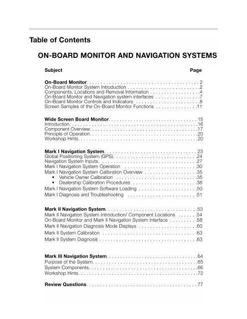
Table of Contents<br />
ON-BOARD MONITOR AND NAVIGATION SYSTEMS<br />
Subject<br />
Page<br />
On-Board Monitor. . . . . . . . . . . . . . . . . . . . . . . . . . . . . . . . . . . . . . . . 2<br />
On-Board Monitor System Introduction . . . . . . . . . . . . . . . . . . . . . . . . . .2<br />
Components, Locations <strong>and</strong> Removal Information . . . . . . . . . . . . . . . . . .4<br />
On-Board Monitor <strong>and</strong> Navigation system interfaces . . . . . . . . . . . . . . . .7<br />
On-Board Monitor Controls <strong>and</strong> Indicators . . . . . . . . . . . . . . . . . . . . . . .8<br />
Screen Samples of the On-Board Monitor Functions . . . . . . . . . . . . . . .11<br />
Wide Screen Board Monitor. . . . . . . . . . . . . . . . . . . . . . . . . . . . . . . . 15<br />
Introduction. . . . . . . . . . . . . . . . . . . . . . . . . . . . . . . . . . . . . . . . . . . . . .16<br />
Component Overview. . . . . . . . . . . . . . . . . . . . . . . . . . . . . . . . . . . . . . .17<br />
Principle of Operation. . . . . . . . . . . . . . . . . . . . . . . . . . . . . . . . . . . . . . .20<br />
Workshop Hints. . . . . . . . . . . . . . . . . . . . . . . . . . . . . . . . . . . . . . . . . . .20<br />
Mark I Navigation System. . . . . . . . . . . . . . . . . . . . . . . . . . . . . . . . . 23<br />
Global Positioning System (GPS). . . . . . . . . . . . . . . . . . . . . . . . . . . . . .24<br />
Navigation System Inputs. . . . . . . . . . . . . . . . . . . . . . . . . . . . . . . . . . .27<br />
Mark I Navigation System Operation . . . . . . . . . . . . . . . . . . . . . . . . . .30<br />
Mark I Navigation System Calibration Overview . . . . . . . . . . . . . . . . . . .35<br />
• Vehicle Owner Calibration . . . . . . . . . . . . . . . . . . . . . . . . . . . . .35<br />
• Dealership Calibration Procedures . . . . . . . . . . . . . . . . . . . . . . .38<br />
Mark I Navigation System Software Loading . . . . . . . . . . . . . . . . . . . . .50<br />
Mark I Diagnosis <strong>and</strong> Troubleshooting . . . . . . . . . . . . . . . . . . . . . . . . .51<br />
Mark II Navigation System. . . . . . . . . . . . . . . . . . . . . . . . . . . . . . . . .53<br />
Mark II Navigation System Introduction/ Component Locations . . . . . . .54<br />
On-Board Monitor <strong>and</strong> Mark II Navigation System Interface . . . . . . . . . .58<br />
Mark II Navigation Diagnosis Mode Displays . . . . . . . . . . . . . . . . . . . . .60<br />
Mark II System Calibration . . . . . . . . . . . . . . . . . . . . . . . . . . . . . . . . . .63<br />
Mark II System Diagnosis . . . . . . . . . . . . . . . . . . . . . . . . . . . . . . . . . . .63<br />
Mark III Navigation System. . . . . . . . . . . . . . . . . . . . . . . . . . . . . . . . . .64<br />
Purpose of the System. . . . . . . . . . . . . . . . . . . . . . . . . . . . . . . . . . . . . .65<br />
System Components. . . . . . . . . . . . . . . . . . . . . . . . . . . . . . . . . . . . . . .66<br />
Workshop Hints. . . . . . . . . . . . . . . . . . . . . . . . . . . . . . . . . . . . . . . . . . .72<br />
Review Questions. . . . . . . . . . . . . . . . . . . . . . . . . . . . . . . . . . . . . . . . 77
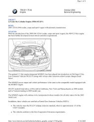
ON-BOARD MONITOR SYSTEM<br />
Model: E38, E39, E53, E46<br />
Production Date: E46 1999 to 2002, all others 1997 to 2001.<br />
Objectives<br />
After completing this module you should be able to:<br />
• Describe the controls possible from the On-Board Monitor.<br />
• Explain the purpose of the ARCNET.<br />
• Know how to operate the various features controlled from the On-Board Monitor.<br />
2<br />
On-Board Monitor <strong>and</strong> Navigation Systems
ON-BOARD MONITOR SYSTEM<br />
The On-board Monitor System was introduced as optional equipment on the 1997 MY<br />
E38s <strong>and</strong> E39s. It was made st<strong>and</strong>ard on the E38 750iL for 1999 <strong>and</strong> st<strong>and</strong>ard for all E38s<br />
in 2000. It uses the latest advances in electronic technology to bring new levels of comfort<br />
<strong>and</strong> convenience to the driver <strong>and</strong> passengers for control of the audio/communication<br />
<strong>systems</strong>. In addition the Mark I Navigation system is incorporated into the total scope<br />
of On-board Monitor Control.<br />
NOTE: The E39 six cylinder models with the On-board Monitor option are equipped with<br />
the high version IKE <strong>and</strong> On Board Computer functions.<br />
The On-board Monitor is<br />
essentially a control <strong>and</strong><br />
display unit. All data<br />
processing <strong>and</strong> calculations<br />
are carried out by the<br />
individual system control<br />
modules. The display data<br />
is sent to the On-board<br />
Monitor over the various<br />
interfaces.<br />
The On-board Monitor is<br />
mounted in the center dash<br />
console. It replaces the<br />
Radio/Tape Player, MID <strong>and</strong><br />
DSP control panel (E38) if<br />
equipped.<br />
It consists of control knobs <strong>and</strong> buttons for programming <strong>and</strong> operating the various<br />
<strong>systems</strong>.<br />
There is a 5 1/4 inch, color LCD screen for display of all system functions. The tape player<br />
drive is also part of the On-Board Monitor unit. However, the radio receiver/amplifier module<br />
is now mounted in the trunk. The audio system is controlled from the on-board <strong>monitor</strong>.<br />
Additionally, the <strong>systems</strong> controlled <strong>and</strong> programmed through the On-board Monitor include:<br />
• On Board Computer<br />
• Navigation system<br />
• Telephone<br />
• Code Function<br />
• Set (on-board <strong>monitor</strong> setup)<br />
• Television (Early production only)<br />
• Digital Sound Processor (DSP)<br />
• Auxiliary Ventilation<br />
• Emergency (provides vehicle location <strong>and</strong><br />
automatically dials telephone for help).<br />
• Monitor Off (Switches the <strong>monitor</strong> off).<br />
3<br />
On-Board Monitor <strong>and</strong> Navigation Systems
COMPONENTS<br />
ON-BOARD MONITOR ASSEMBLY<br />
The on-board <strong>monitor</strong> assembly is mounted in the center console.<br />
following components:<br />
It consists of the<br />
• On-board <strong>monitor</strong> housing with Cassette tape<br />
player.<br />
• 5 1/4 inch<br />
color LCD<br />
display<br />
screen.<br />
• BMBT. BMBT is a German acronym meaning, “Board Monitor Bedien Tiel”. Translated<br />
to English this means On-Board Monitor Control Module/Panel. The BMBT is<br />
connected to the I-BUS. It provides the same function as the pushbutton inputs <strong>and</strong><br />
output illumination of the LEDs of the familiar MID.<br />
REMOVAL OF ON-BOARD MONITOR ASSEMBLY FROM CENTER CONSOLE<br />
The on-board <strong>monitor</strong> is removed from the center console<br />
as an assembly as follows.<br />
REMOVE WOOD TRIM<br />
1. Remove the wood trim from the dash on both sides of<br />
the on-board <strong>monitor</strong>.<br />
2. Unscrew the metal plates (E38) or unhook the latches (E39)<br />
from each side of the on-board <strong>monitor</strong> <strong>and</strong> loosen the<br />
recessed screw from the lower edge of the wood trim.<br />
LOOSEN SCREW<br />
3. Remove the on-board <strong>monitor</strong> wood trim<br />
4. With the on-board <strong>monitor</strong> wood trim removed,<br />
unscrew the four large torx TM screws as shown.<br />
5. Pull the on-board <strong>monitor</strong> assembly out of the center<br />
console.<br />
For complete procedures refer to group 65 repair manual in TIS.<br />
4<br />
On-Board Monitor <strong>and</strong> Navigation Systems
The following components are mounted in the trunk on the left side behind the<br />
trim cover<br />
Mark I<br />
NAVIGATION<br />
COMPUTER<br />
MODULE<br />
It contains a microprocessor<br />
<strong>and</strong> CD<br />
drive for <strong>navigation</strong><br />
system operation.<br />
The <strong>navigation</strong><br />
computer is linked<br />
directly to the<br />
video module<br />
which provides the<br />
visual <strong>and</strong> audio<br />
output instructions<br />
for the <strong>navigation</strong><br />
system.<br />
AUDIO SYSTEM<br />
AMPLIFIER<br />
RADIO<br />
RECEIVER<br />
AUDIO SYSTEM<br />
CD CHANGER<br />
VIDEO MODULE<br />
The video module<br />
generates the Red,<br />
Green <strong>and</strong> Blue<br />
video signals for the<br />
on-board <strong>monitor</strong><br />
LCD screen. The<br />
RGB signals are for<br />
all functions of the<br />
on-board <strong>monitor</strong><br />
including the nav.<br />
system.<br />
The video module<br />
also serves as a<br />
data memory for the<br />
<strong>navigation</strong> system.<br />
As needed the<br />
video module<br />
instantly provides<br />
the RGB signals to<br />
change the <strong>onboard</strong><br />
<strong>monitor</strong>s<br />
display <strong>and</strong> sends<br />
the audio signals to<br />
the audio system<br />
amplifier.<br />
GLOBAL POSITIONING RECEIVER MODULE (GPS)<br />
The module determines the exact position of the vehicle from known orbits of GPS<br />
satellites. The GPS receiver interfaces with the Navigation computer module for<br />
determining the vehicle position.<br />
NAVIGATION COMPUTER REMOVAL:<br />
To remove the nav. computer from the mounting<br />
bracket insert four small phillips head<br />
screwdrivers into the four holes on the face<br />
plate. Push the screwdrivers in past a slight<br />
detent. Pull the nav. computer out of the mounting bracket.<br />
5<br />
On-Board Monitor <strong>and</strong> Navigation Systems
The following components are located on the rear parcel shelf under the trim<br />
panel.<br />
MAGNETIC FIELD SENSOR<br />
The magnetic field sensor is a<br />
small micro processor. It is used<br />
while the <strong>navigation</strong> system is<br />
operating to determine the<br />
vehicle’s direction of travel.<br />
GLOBAL POSITIONING<br />
RECEIVER ANTENNA<br />
The antenna picks up the signals<br />
from the satellites <strong>and</strong> transmits<br />
them to the GPS module.<br />
Carry over components that are part of the On-Board Monitor / Navigation system<br />
include:<br />
• Instrument Cluster Control Module (IKE) for On Board Computer calculations<br />
• Multi-Function Steering Wheel (MFL) for radio <strong>and</strong> telephone control functions.<br />
• Telephone h<strong>and</strong>set for operation of the phone.<br />
• ASC control module for the two front wheel speed sensor inputs.<br />
6<br />
On-Board Monitor <strong>and</strong> Navigation Systems
ON-BOARD MONITOR AND NAVIGATION SYSTEM INTERFACES<br />
I BUS - The On-board Monitor Control Module/Panel is connected to the I-Bus for<br />
communication with the other I-Bus components. Data communication takes place over<br />
the I-Bus between the BMBT <strong>and</strong> the following modules:<br />
• IKE<br />
• Telephone H<strong>and</strong>set<br />
• Multi-Function Steering Wheel (MFL)<br />
• Radio Receiver<br />
• Video Module<br />
• Audio System Amplifier<br />
ARCNET - The Attached Resource<br />
Computing Network is a high speed (2<br />
MB/sec) digital data link. The Navigation<br />
Computer <strong>and</strong> Video Module are<br />
connected by the ARCNET for isolated<br />
high speed <strong>navigation</strong> system<br />
communication.<br />
The ARCNET is made up of two data<br />
wires <strong>and</strong> a shield similar to the familiar<br />
CAN data link. The shielded ARCNET<br />
cable has its own triaxial type connector<br />
ends that are pushed onto their mating<br />
connectors on the modules.<br />
Video Module Red, Green Blue (RGB) output - The On Board Monitor is connected to<br />
the Video module through the RGB connection for the LCD screen displays. Each of the<br />
three color signals is shielded.<br />
7<br />
On-Board Monitor <strong>and</strong> Navigation Systems
ON-BOARD MONITOR CONTROLS & INDICATORS<br />
AUDIO SYSTEM<br />
Operation of the audio system (radio/tape/CD) is similar to current <strong>systems</strong> installed in other<br />
models. The major difference is that the display of stations <strong>and</strong> settings is through the LCD<br />
panel.<br />
Tape program <strong>and</strong><br />
eject buttons.<br />
1-6 buttons correspond to stored radio stations (12+6<br />
Auto) <strong>and</strong> CD selections (CD 1-6 selection).<br />
Weather B<strong>and</strong>, FM - AM, Dolby <strong>and</strong> Mode Selection.<br />
Mode = Radio, Tape or CD function.<br />
Switches the<br />
audio system<br />
on/off (PUSH)<br />
<strong>and</strong> adjusts the<br />
volume<br />
(ROTATE).<br />
Both the radio<br />
<strong>and</strong> the<br />
<strong>monitor</strong> display<br />
are switched<br />
Toggles the<br />
audio display in<br />
the <strong>monitor</strong><br />
back to the<br />
previous<br />
screen.<br />
Amber LED<br />
illuminated<br />
when radio is<br />
on.<br />
Arrow rocker switch.<br />
Adjusts the tone settings<br />
<strong>and</strong> is used for the<br />
seek/scan function for the<br />
radio, tape <strong>and</strong> CD track.<br />
TONE-SELECT<br />
Tone: Adjusts the bass, treble, balance <strong>and</strong><br />
fader using the tone & arrow buttons.<br />
Select: provides choice of station selection<br />
method, ie: Manual, Scan, Scan Sensitivity.<br />
8<br />
On-Board Monitor <strong>and</strong> Navigation Systems
TELEPHONE BUTTON AND INDICATORS<br />
Send/End button. As on previous <strong>systems</strong> this button sends the call to the displayed<br />
telephone number in the On-Board Monitor display or ends the current call.<br />
The telephone LEDs correspond to the E38/E39 MID:<br />
Green = Phone call in progress<br />
Red = Phone is on<br />
Amber = Steady: Roaming in same type system as home system<br />
Flashing: Roaming in different type system as home system<br />
Fan Symbol: Flashing indicates the park car ventilation system is programmed for<br />
activation. Steady indicates the parked car ventilation is currently on.<br />
Clock Button: Displays the time with the key switched OFF. Additionally, this button<br />
also switches the parked car ventilation system to off when it is on.<br />
ON SCREEN CONTROLS<br />
There are two main controls for all of the <strong>monitor</strong> screen displays.<br />
MENU BUTTON<br />
The menu button is used<br />
to call up the Main Menu<br />
as shown at right.<br />
This Menu provides<br />
access to all of the On-<br />
Board Monitor functions<br />
including:<br />
ROTARY KNOB<br />
PUSH = Switches the <strong>monitor</strong> on or activates the selected program displayed<br />
in the <strong>monitor</strong>.<br />
ROTATE = Selects the desired function for programming or display<br />
9<br />
On-Board Monitor <strong>and</strong> Navigation Systems
CHECK<br />
ENGINE<br />
ABS/ASC<br />
10<br />
On-Board Monitor <strong>and</strong> Navigation Systems
SCREEN SAMPLES OF THE ON-BOARD MONITOR FUNCTIONS<br />
ON BOARD COMPUTER<br />
The functions of the On Board<br />
Computer remain the same as<br />
previous <strong>systems</strong>. All On Board<br />
Computer calculations are still<br />
performed by the IKE.<br />
The OBC is called up from the Onboard<br />
Monitor main menu by<br />
highlighting the BC <strong>and</strong> pressing the<br />
knob.<br />
Once the computer functions are<br />
displayed, all programming <strong>and</strong><br />
resetting of the displays is carried out<br />
using the rotary knob.<br />
MARK I GPS NAVIGATION<br />
The on-board <strong>monitor</strong> provides<br />
access to the new Navigation system.<br />
The Mark I Navigation system is<br />
controlled <strong>and</strong> displayed via the <strong>onboard</strong><br />
<strong>monitor</strong>.<br />
11<br />
On-Board Monitor <strong>and</strong> Navigation Systems
TELEPHONE<br />
Selecting the Telephone function on<br />
the Monitor screen will call up a rotary<br />
dial display. The telephone can be<br />
dialed with the rotary knob by turning<br />
the knob <strong>and</strong> pressing it when the<br />
desired digit is highlighted. Once the<br />
number is input, the call is initiated by<br />
pressing the send/end button at the<br />
left of the Monitor.<br />
All telephone programming is carried<br />
out through the h<strong>and</strong>set as on other<br />
telephone models.<br />
Other features of the <strong>monitor</strong><br />
telephone control include:<br />
• Memory storage <strong>and</strong> recall<br />
• Information on signal strength <strong>and</strong><br />
call timer<br />
• Top 8 number storage<br />
• Emergency call feature<br />
- Displays 911 or Assist.<br />
- Displays the vehicles current<br />
coordinates in latitude <strong>and</strong><br />
longitude along with the street<br />
name (if the street is on the<br />
digitized map database).<br />
CODE FUNCTION<br />
The familiar BC code function is<br />
carried over to the On-board Monitor<br />
system. A four digit code can be<br />
entered into the system that will<br />
disable the vehicle from starting as<br />
with previous <strong>systems</strong>.<br />
12<br />
On-Board Monitor <strong>and</strong> Navigation Systems
SET (On-Board Monitor Setup<br />
Utility)<br />
The Set Menu provides the on-board<br />
<strong>monitor</strong> display set up. This includes:<br />
• Language Selection<br />
• Time/date set <strong>and</strong> format<br />
• Etc.<br />
The “Audio+BC” selection at the<br />
bottom of the list switches the BC<br />
display off when the audio display is in<br />
the <strong>monitor</strong>.<br />
TELEVISION<br />
Early production only! The<br />
television function will be selectable<br />
from the main menu. Though audio<br />
is heard, television images will not<br />
display in the On-board Monitor.<br />
E38: vehicles are prewired for<br />
television viewing in the rear seat. A<br />
TV <strong>monitor</strong> connector is located in the<br />
rear of the center console for this<br />
purpose. This is only possible with<br />
owner purchased equipment. The<br />
On-board <strong>monitor</strong> will only serve as<br />
the controller for rear seat television.<br />
NOTE: US Law prohibits television<br />
display in the front seat viewing<br />
area.<br />
DIGITAL SOUND PROCESSOR<br />
(DSP)<br />
The DSP system, introduced with the<br />
E38 is controlled <strong>and</strong> programmed<br />
through the On-board Monitor.<br />
13<br />
On-Board Monitor <strong>and</strong> Navigation Systems
AUXILIARY VENTILATION<br />
The control <strong>and</strong> programming of the<br />
auxiliary ventilation feature is done<br />
with the on-board <strong>monitor</strong>. Use the<br />
rotary knob to program the on times<br />
for system operation.<br />
EMERGENCY<br />
The Emergency function provides the<br />
exact location of the vehicle including:<br />
• Street <strong>and</strong> Town (if on digitized map)<br />
• Longitude <strong>and</strong> Latitude<br />
Coordinates<br />
If the vehicle is equipped with a<br />
telephone, 911 or Assist (<strong>BMW</strong><br />
roadside assistance) can be called<br />
directly from this screen.<br />
If the vehicle is not equipped with a<br />
phone the emergency program<br />
provides your location.<br />
MONITOR OFF<br />
Pressing the “Monitor Off” button switches the <strong>monitor</strong> to a blank screen. All programs are<br />
still functioning but not displayed in the <strong>monitor</strong>. The <strong>monitor</strong> is turned back on by pressing<br />
or turning any button on the on-board <strong>monitor</strong>.<br />
14<br />
On-Board Monitor <strong>and</strong> Navigation Systems
WIDE SCREEN ON-BOARD MONITOR<br />
Model: E39,E38,E46,E53<br />
Production Date: E38,E39 from 9/00<br />
E53 from 1/01<br />
E46 Cabrio from 3/01<br />
all other E46 models from 9/01<br />
Objectives<br />
After completing this module you should be able to:<br />
• Describe the benefits of the wide screen <strong>monitor</strong> over the previous versions.<br />
• Underst<strong>and</strong> how to operate the wide screen <strong>monitor</strong>.<br />
• Review the procedures to access the Service Modes.<br />
15<br />
On-Board Monitor <strong>and</strong> Navigation Systems
Introduction<br />
While the instrument cluster provides all of the important vehicle status information to the<br />
driver, the on-board <strong>monitor</strong> is designed as an additional display that can be viewed by both<br />
the driver <strong>and</strong> vehicle passengers. Information relating to the vehicle, <strong>navigation</strong>, audio system<br />
<strong>and</strong> telephone can be displayed <strong>and</strong> controlled from a central location.<br />
The wide screen on-board <strong>monitor</strong> replaces both the 5.5’’ versions in the E38 <strong>and</strong> E39, <strong>and</strong><br />
the 5’’ board <strong>monitor</strong> from the E53 <strong>and</strong> E46. The wide screen display has a screen size of<br />
6.5’’ <strong>and</strong> an aspect ratio (length:height) of 16:9.<br />
The benefits of the wide screen design are:<br />
• Larger display area <strong>and</strong> higher resolution (400X234 pixels).<br />
• Improved display screen technology (Ad-TFT LC).<br />
• Bigger text size.<br />
• Soft keys replace country specific audio function keys.<br />
• Used for all board <strong>monitor</strong> applications in all markets reducing variants.<br />
• Larger display area makes split screen <strong>and</strong> magnification features possible (future<br />
software enhancements).<br />
16<br />
On-Board Monitor <strong>and</strong> Navigation Systems
Component Overview<br />
The wide screen on-board <strong>monitor</strong> consists<br />
of:<br />
1. Monitor housing with cassette drive<br />
2. Display screen<br />
3. On-board <strong>monitor</strong> control panel<br />
Cassette Drive<br />
The cassette drive is located behind the on-board <strong>monitor</strong> screen. In order to access the<br />
cassette, press the “eject” button, the display screen tilts forward to uncover the cassette<br />
slot. The images will remain displayed on the screen.<br />
After pressing the “eject” button again or automatically after 15 seconds the display returns<br />
to its normal position (cassette must be completely inside or removed). The tilt mechanism<br />
for the display screen utilizes anti-trap, if the board <strong>monitor</strong> detects a sudden change in<br />
speed, the display will reverse direction.<br />
17<br />
On-Board Monitor <strong>and</strong> Navigation Systems
Display Screen <strong>and</strong> Control Panel<br />
The display screen has a diagonal width of 6.5’’ <strong>and</strong> an aspect ratio of 16:9 compared to<br />
the previous <strong>monitor</strong>s that had a ratio of 4:3. The new screen also uses a Ad-TFT display<br />
(Advanced Thin Film Transistor). This type of screen uses ambient light in addition to backlighting<br />
in order to illuminate the display. The advantage is a constant contrast <strong>and</strong><br />
brightness level at all ambient lighting conditions. 6.5 INCH DISPLAY<br />
16:9 ASPECT RATIO<br />
INFO<br />
1 4<br />
MENU<br />
2 5<br />
On-board computer<br />
GPS-Navigation<br />
3 6<br />
FM AM<br />
MODE<br />
DSP<br />
Code<br />
Set<br />
Aux. Ventilation<br />
Emergency<br />
Monitor off<br />
TONE SELECT<br />
MENU<br />
11.13.2000 Thursday 10:17<br />
RADIO CONTROL KNOB<br />
PHOTOCELL SENSOR ON-BOARD MONITOR CONTROL<br />
RADIO STATUS LED = Signal from<br />
radio via I/K bus.<br />
KNOB<br />
AUXILIARY FAN INDICATOR LED<br />
INFO<br />
INFO = Activates the soft key menu for RDS <strong>and</strong> PTY<br />
1 4<br />
2 5<br />
1-6 BUTTONS = Audio presets <strong>and</strong> CD selection<br />
3 6<br />
FM<br />
AM<br />
AM/FM SELECTION<br />
MODE MODE/DISPLAY = Mode selects between audio functions. Display alternates between<br />
radio display <strong>and</strong> other displays. BC,TEL,NAV etc.<br />
TELEPHONE STATUS LEDs / EJECT = Tilts <strong>monitor</strong> to access cassette drive.<br />
TELEPHONE = Send/End button<br />
TAPE REVERSE/CLOCK = Clock: Pressing with key off displays time. Aux. ventilation<br />
can be switched by holding button longer.<br />
TONE/SELECT=Tone: Dolby (cassette only) <strong>and</strong> audio adjustments.<br />
Select: Choose between station search methods (a,m or scan).<br />
FAST FORWARD/REVERSE / STATION SEARCH<br />
MENU = Returns display to main menu<br />
18<br />
On-Board Monitor <strong>and</strong> Navigation Systems<br />
TONE SELECT<br />
MENU
80<br />
60<br />
140<br />
km/h<br />
ELECTRONIC<br />
220<br />
240<br />
miles<br />
Wide Screen Board Monitor Interface<br />
K-BUS<br />
0<br />
½<br />
60<br />
40<br />
40<br />
20 20<br />
120<br />
100<br />
80<br />
MPH<br />
100<br />
160<br />
180<br />
200<br />
120<br />
140<br />
!<br />
3 4<br />
1/min<br />
2<br />
5<br />
x 1000<br />
1<br />
6<br />
0<br />
7<br />
40<br />
0<br />
20 15 10<br />
DIAGNOSIS BUS<br />
CHECK<br />
ENGINE<br />
OIL SERVICE<br />
INSPECTION<br />
123456 122 4 + 72 0F PRND SM<br />
20 DIGIT READOUT<br />
54321<br />
P<br />
! ABS<br />
StarTAC<br />
Telephone<br />
PSE Box<br />
B M W<br />
SRS<br />
AIRBAG<br />
<strong>BMW</strong><br />
MFL-CM<br />
AMPLIFIER<br />
I-BUS<br />
LCM III<br />
AUDIO SIGNALS<br />
FOR AMPLIFICATION<br />
INFO<br />
1 4<br />
BM53<br />
2 5<br />
3 6<br />
FM AM<br />
MODE<br />
TONE SELECT<br />
MENU<br />
CD<br />
PLAYER<br />
AUDIO<br />
SIGNALS<br />
GPS<br />
ANTENNA<br />
NAVIGATION<br />
AUDIO<br />
SIGNALS<br />
TAPE PLAYER<br />
AUDIO SIGNALS<br />
POWER<br />
GPS NAVIGATION SYSTEM<br />
REVERSE SIGNAL FROM<br />
LCM<br />
13.07.2000 Thursday 10:17<br />
RED SIGNAL<br />
GREEN SIGNAL<br />
BLUE SIGNAL<br />
DSC<br />
(processed<br />
left front wheel<br />
speed signal)<br />
BOSCH<br />
Example of E38/E39 with Wide Screen Board Monitor<br />
19<br />
On-Board Monitor <strong>and</strong> Navigation Systems
Principle of Operation<br />
The on-board <strong>monitor</strong> is an input <strong>and</strong> display device that performs no internal calculations.<br />
Inputs from the control panel buttons <strong>and</strong> knobs are converted into I-bus (K-bus E46)<br />
signals by the BM control panel. All of the devices controlled by the BM are connected to<br />
the I/K bus interface.<br />
The <strong>navigation</strong> computer contains the graphics stage integrated into the <strong>navigation</strong><br />
computer housing. Request for on-board <strong>monitor</strong> displays are made to the <strong>navigation</strong><br />
computer via the I/K bus. The <strong>navigation</strong> computer generates the RGB video signals <strong>and</strong><br />
transmits them via 3 shielded wires.<br />
Audio signals generated by the cassette drive are sent via traditional audio wires (4) to the<br />
radio (located in the trunk or cargo area) for output to the audio system amplifier.<br />
Workshop Hints<br />
Service mode<br />
Access for the radio, on-board <strong>monitor</strong> <strong>and</strong> <strong>navigation</strong> service modes is available through<br />
the on-board <strong>monitor</strong> screen.<br />
To enter the radio service mode:<br />
• Turn the ignition key to position 1 (KLR).<br />
• Turn the radio on, then off, then on again.<br />
• Press the “INFO” button. From the selection list choose “RDS”.<br />
• Press <strong>and</strong> hold the on-board <strong>monitor</strong> control knob for at least 8 seconds.<br />
• The audio display window will show the radio serial number as the first display.<br />
• The station search < > buttons are used to scroll through the various settings.<br />
• Turn off the radio to “set” any changes made.<br />
1<br />
INFO<br />
1 4<br />
2 5<br />
3 6<br />
FM AM<br />
MODE<br />
INFO<br />
PTY<br />
RDS<br />
2<br />
Note: See the “NG” Radios<br />
module for a list of the<br />
tests <strong>and</strong> settings available<br />
in the radio service mode.<br />
TONE SELECT<br />
MENU<br />
11.13.2000 Thursday 10:17<br />
3<br />
20<br />
On-Board Monitor <strong>and</strong> Navigation Systems
To enter the On-Board Monitor <strong>and</strong> Navigation Service Mode:<br />
• Turn the ignition key to position 1 (KL R).<br />
• From the Menu screen select “SET”.<br />
• Once in the Set screen, press <strong>and</strong> hold the “MENU” button for 8 seconds.<br />
• The Service Mode menu will appear on the display.<br />
• Select “On-board <strong>monitor</strong>” for <strong>monitor</strong> specific tests.<br />
INFO<br />
1 4<br />
2 5<br />
3 6<br />
FM AM<br />
MODE<br />
SET<br />
Language<br />
Distance<br />
Consumpt.<br />
Temp.<br />
Clock<br />
USA<br />
km<br />
1/100km<br />
C<br />
24h<br />
E<br />
miles<br />
mpg<br />
F<br />
12h<br />
SW 3-1/20<br />
km/l<br />
set<br />
Date<br />
dd.mm mm/dd set<br />
Audio+OBC<br />
on off<br />
11.13.2000 Thursday 10:17<br />
TONE SELECT<br />
MENU<br />
INFO<br />
1 4<br />
2 5<br />
3 6<br />
FM AM<br />
MODE<br />
SERVICE MODE<br />
On-board <strong>monitor</strong><br />
NAVIGATION/GRAPHIC ELEMENT<br />
Video Module<br />
GPS<br />
Sensor check<br />
Telematics<br />
11.13.2000 Thursday 10:17<br />
TONE SELECT<br />
MENU<br />
Press <strong>and</strong> hold for 8 seconds after entering<br />
the “SET” screen.<br />
Service Mode main menu display<br />
INFO<br />
1 4<br />
2 5<br />
3 6<br />
FM AM<br />
MODE<br />
ON-BOARD MONITOR VERSION<br />
Sw level<br />
Hw level:<br />
Diag. Index:<br />
Bus index:<br />
Encoding index:<br />
Supplier<br />
return<br />
Version<br />
Key function<br />
Brightness<br />
Return<br />
Functions<br />
11.13.2000 Thursday 10:17<br />
TONE SELECT<br />
MENU<br />
Tests <strong>and</strong> adjustments available for the on-board <strong>monitor</strong> are:<br />
• Version Information<br />
• Key Function (button <strong>and</strong> rotary knob test)<br />
• Brightness (Screen brightness adjustment)<br />
21<br />
On-Board Monitor <strong>and</strong> Navigation Systems
Diagnosis<br />
Fault driven diagnosis is possible using the DIS/MoDiC Diagnosis Program. The Diagnosis<br />
Program features:<br />
• Identification<br />
• Read/Clear fault memory<br />
• Diagnosis requests<br />
• Fault driven test modules. (E46 concept)<br />
<strong>BMW</strong> DIS<br />
<strong>BMW</strong> DIS<br />
<strong>BMW</strong> DIS<br />
22<br />
On-Board Monitor <strong>and</strong> Navigation Systems
Mk-1 NAVIGATION SYSTEM<br />
Model: E38, E39<br />
Production Date: 10/96 to 9/97<br />
Objectives<br />
After completing this module you should be able to:<br />
• Underst<strong>and</strong> the principles of GPS Navigation.<br />
• List the components used in the Mk-1 system.<br />
• Recognize the reasons that would require a system calibration.<br />
23<br />
On-Board Monitor <strong>and</strong> Navigation Systems
GPS - NAVIGATION SYSTEM<br />
GLOBAL POSITIONING SYSTEM (GPS)<br />
The <strong>BMW</strong> Navigation system operates in conjunction with the Global Positioning System<br />
(GPS). Utilization of the GPS improves the accuracy <strong>and</strong> provides redundancy for the<br />
Navigation system which also incorporates a dead reckoning system. The GPS was<br />
designed by the US Government in the 1970s for military purposes. In recent years it has<br />
been made available for civilian use.<br />
There are 24 satellites equally divided among six orbits that are positioned 11,000 miles out<br />
in space. Each satellite continuously emits a radio signal. The signals contain short<br />
information messages including:<br />
• The exact time the message was broadcast.<br />
• Current latitude <strong>and</strong> longitude positions relative to the orbit.<br />
24<br />
On-Board Monitor <strong>and</strong> Navigation Systems
A GPS receiver device on earth receives these signals from the satellites <strong>and</strong> determines its<br />
own location by:<br />
• Comparing its internal clock signal with the satellites.<br />
This determines the distance from the satellites<br />
location.<br />
• Through triangulation computation, the receiver<br />
module calculates its own longitude <strong>and</strong><br />
latitude position. This is only possible when it<br />
receives a minimum of three satellite signals.<br />
In a sense, GPS can be compared to <strong>navigation</strong> methods used by sailing ship navigators<br />
years ago. They used a sextant to plot the changing locations of known stars to determine<br />
their own position. This, in conjunction with compass <strong>navigation</strong>, proved an accurate<br />
method of sailing across the seas.<br />
25<br />
On-Board Monitor <strong>and</strong> Navigation Systems
The <strong>BMW</strong> <strong>navigation</strong> system is based on the CARiN TM system developed by Philips<br />
Electronics. CARiN TM = Car Information <strong>and</strong> Navigation System.<br />
The <strong>BMW</strong> Navigation system is a CD driven, on board, active route mapping computer. The<br />
driver can enter a destination through the On Board <strong>monitor</strong> <strong>and</strong> the <strong>navigation</strong> system will<br />
select a mapped route, from the current location, to the destination.<br />
The route maps are stored digitally on a<br />
<strong>navigation</strong>al database CD that is installed in<br />
a dedicated CD drive in the <strong>navigation</strong><br />
computer.<br />
The U.S. is divided into 7 mapped CD<br />
database areas ranging from:<br />
• Area 1- California <strong>and</strong> Nevada, through<br />
• Area 7 - Covering the South Eastern States.<br />
In addition to the digitized route maps, other information such as hotels, restaurants,<br />
service stations, dealerships, points of interest <strong>and</strong> local sight-seeing attractions along with<br />
their addresses are stored on the database CD.<br />
The map CDs are currently being updated twice a year. As the updates occur, more streets<br />
<strong>and</strong> roads will be added. In addition, more local information will be added with regards to<br />
businesses, hotels, motels, local attractions, etc.<br />
26<br />
On-Board Monitor <strong>and</strong> Navigation Systems
MARK I NAVIGATION COMPUTER INPUTS<br />
The Mark I Navigation computer relies on the digitized map CD data to calculate the routes<br />
to the selected destinations. The Nav. computer also relies on accurate input signals from<br />
the vehicle to calculate the exact coordinates of the vehicle at all times.<br />
GPS INPUT SIGNAL: The GPS receiver<br />
module communicates with the<br />
<strong>navigation</strong> computer over a four wire bidirection<br />
interface.<br />
The Navigation computer requests the<br />
exact coordinates of the vehicle over the<br />
RXD-RXDN link. The GPS receiver<br />
module responds with the data over the<br />
TXD-TXDN link.<br />
GPS<br />
ANTENNA<br />
Each two wire link is similar to the CAN line signal but unidirectional. When a data burst is<br />
transmitted it is mirrored on the other wire as a self check of the data transmission.<br />
The GPS receiver module is provided KL 30 to maintain vehicle position in memory. When<br />
KL R is switched on the receiver module resumes <strong>monitor</strong>ing the satellite radio signals<br />
picked up from the GPS aerial. The link to the GPS antennal is a gold plated coaxial<br />
connector.<br />
27<br />
On-Board Monitor <strong>and</strong> Navigation Systems
MAGNETIC FIELD SENSOR<br />
In addition to the vehicle’s current position, the <strong>navigation</strong> computer also needs a direction<br />
of travel input. The magnetic field sensor is used for this purpose.<br />
The sensor consists of a ferromagnetic ring with two coils of wire placed 90 O apart. Signals<br />
from the two coils become the vehicle’s directional input when the <strong>navigation</strong> system is in<br />
operation.<br />
SENSOR OPERATION<br />
The sensor receives its operating power <strong>and</strong> ground from the <strong>navigation</strong> computer. When<br />
the system is switched on, magnetic fields are induced into the coils. The coils produce a<br />
voltage signal that is input to the <strong>navigation</strong> computer.<br />
As the vehicle turns to the left or right, the earth’s magnetic field influences the coil’s<br />
magnetic fields causing them to increase <strong>and</strong> decrease.<br />
The changing strength of the magnetic fields causes the voltage signal induced in the coils<br />
to increase <strong>and</strong> decrease linearly. This creates a changing voltage drop at the <strong>monitor</strong> in the<br />
<strong>navigation</strong> computer.<br />
The <strong>navigation</strong> computer determines the direction of travel of the vehicle by plotting the<br />
simultaneously changing voltage signals.<br />
28<br />
On-Board Monitor <strong>and</strong> Navigation Systems
FRONT WHEEL SPEED SENSORS<br />
The <strong>navigation</strong> computer is provided with the front wheel speed signals to track the vehicle<br />
speed/distance <strong>and</strong> turning.<br />
ABS/ASC<br />
REVERSE GEAR SELECTED<br />
The nav. computer receives a 12 volt signal from the LCM when the back up lights are<br />
illuminated. This signal informs the nav. computer that the vehicle is being driven in reverse.<br />
REAR WINDOW DEFROSTER ON SIGNAL<br />
When the rear window<br />
defroster is switched on the<br />
nav. computer is informed<br />
via the vehicle bus system:<br />
• IHKA to the IKE (Kbus)<br />
• IKE to video module (Ibus)<br />
• Video module to the nav.<br />
computer (ARCNET)<br />
When the nav. computer receives<br />
the signal, it compensates for the<br />
magnetic influence from the rear<br />
defroster.<br />
This compensation is derived<br />
from the dealership calibration<br />
procedure.<br />
29<br />
On-Board Monitor <strong>and</strong> Navigation Systems
MARK I NAVIGATION SYSTEM OPERATION<br />
NOTE: There are several methods for<br />
entering destinations into the<br />
<strong>navigation</strong> system computer. The<br />
following example uses the rotary knob<br />
to input a destination from the input<br />
destination screen.<br />
Enter the <strong>navigation</strong> system by<br />
pressing the GPS-Navigation button<br />
from the main menu.<br />
After acknowledging the system<br />
warning, any previously entered<br />
destination is displayed. This destination<br />
must be deleted or overwritten in order<br />
to input a new destination.<br />
The rotary knob is used to enter a<br />
city/town from an Alpha-Numeric<br />
menu or the destination can be<br />
selected from the index of listed<br />
locations that are mapped on the CD.<br />
Next the desired street is entered in the<br />
same fashion. The street number can<br />
also be entered at this time. If the<br />
street number is on the database CD,<br />
the nav. system will guide the driver<br />
directly to the house number.<br />
There are two choices for route<br />
preference available from this screen,<br />
• “most use of highways”<br />
• “least use of highways”<br />
With either selection, the system will<br />
pick the most direct route to the<br />
destination, based on the selection.<br />
Once the location has been entered,<br />
the <strong>navigation</strong> system is ready for<br />
guidance. Press the directions button.<br />
30<br />
On-Board Monitor <strong>and</strong> Navigation Systems
The system will guide the driver via:<br />
• The graphical direction display - which consist of arrows <strong>and</strong> text that show the<br />
current location, the destination <strong>and</strong> direction of travel. When turns or intersections<br />
approach, a voice comm<strong>and</strong> will inform the driver when to turn.<br />
• The graphical map display - which consists of a digital road map showing the entered<br />
route, destination <strong>and</strong> vehicle position.<br />
In either display mode a voice comm<strong>and</strong> will inform the driver when to turn when turns or<br />
intersections approach.<br />
The <strong>navigation</strong> screen display can be turned OFF (from main menu) <strong>and</strong> the system will<br />
remain in operation. The voice comm<strong>and</strong> will continue to inform the driver when to turn.<br />
31<br />
On-Board Monitor <strong>and</strong> Navigation Systems
GRAPHICAL MAP SCALE<br />
The graphical map display can be<br />
scaled up or down from 400 feet to 50<br />
miles depending on the distance to the<br />
destination.<br />
This function is activated by turning the<br />
knob one click, <strong>and</strong> a sub menu will<br />
display on screen. Choose “Scale”<br />
<strong>and</strong> adjust as needed.<br />
GRAPHICAL MAP POSITIONING<br />
The graphical map can be displayed “North Pointing” or “Direction of travel”. This function<br />
is also accessed by turning the knob one “click” as described above.<br />
North Pointing = Top of map is<br />
always facing north.<br />
Direction of Travel = Top of map<br />
is always facing direction of vehicle<br />
32<br />
On-Board Monitor <strong>and</strong> Navigation Systems
GPS INDICATION<br />
Satellite reception, by the <strong>navigation</strong> system, is indicated in the upper right corner of the<br />
display screen. The number of satellite signals being received by the system is indicated<br />
by small white dots in the display that surround the picture of the globe. In addition, the<br />
GPS logo is displayed at the bottom of the graphic.<br />
The number of dots indicate the number of satellite signals that the <strong>navigation</strong> computer is<br />
receiving.<br />
If only the globe graphic is displayed, without the dots or logo, the vehicle is in a poor<br />
reception area or the signals are being blocked by some obstruction. The dead reckoning<br />
function of the compass <strong>and</strong> wheel sensors provide adequate <strong>navigation</strong> in this situation.<br />
If the dots <strong>and</strong> logo fail to display in a known good reception area, than a fault is indicated<br />
<strong>and</strong> troubleshooting should be carried out according to the fault symptom ‘GPS Problems”.<br />
33<br />
On-Board Monitor <strong>and</strong> Navigation Systems
NAVIGATION SYSTEM INFORMATION SCREEN<br />
The Information screen provides access to the balance of the <strong>navigation</strong> system features<br />
including:<br />
Information on destination or current<br />
location provides a detailed list of<br />
stored points of interest such as:<br />
• Gas stations<br />
• Banks<br />
• Restaurants<br />
• Hotels, etc.,<br />
This feature allows the user to enter the<br />
point of interest <strong>and</strong> change the route<br />
to guide the driver to the entered point.<br />
VEHICLE POSITION<br />
The vehicle position selection from this<br />
screen provides access to the<br />
Calibration function of the <strong>navigation</strong><br />
system.<br />
34<br />
On-Board Monitor <strong>and</strong> Navigation Systems
MARK I NAVIGATION SYSTEM CALIBRATION<br />
The Mark I <strong>navigation</strong> system will require “calibration” at some point in it’s service life. The<br />
reasons that cause the necessity of a calibration procedure are as varied as inaccurate<br />
<strong>navigation</strong> display data, after the installation of a new set of tires, to the replacement of a<br />
shattered rear window.<br />
Calibration procedures are divided into two categories<br />
• Vehicle Owner Calibration - Calibration that the vehicle owner can perform.<br />
• Dealership Calibration - Procedures only an authorized dealer can perform.<br />
This section is divided into these two categories. Always consider what the owner of the<br />
vehicle could have inadvertently changed when troubleshooting <strong>and</strong>/or calibrating the vehicle.<br />
Check these data inputs before you embark on a full dealership calibration procedure.<br />
VEHICLE OWNER CALIBRATION<br />
The vehicle owner’s manual contains the information on how to set the vehicle position <strong>and</strong><br />
adjust the tire calibration. Both of these adjustments are found on the vehicle position<br />
screen which is accessed from the information screen as shown on page 24.<br />
“The Owner Calibration Procedures shown on pages 25-27 are for information<br />
purposes only. A full Dealership Calibration is the recommended method for<br />
accurate system calibration.”<br />
1. RESETTING VEHICLE POSITION<br />
A mis-located vehicle is caused by driving in <strong>and</strong> out of the digitized map areas or starting<br />
a vehicle after it has traveled on a flat bed or train. The system will eventually relocate itself<br />
automatically through GPS but it can be entered through the on-board <strong>monitor</strong> for<br />
immediate resetting.<br />
From the Vehicle Position Screen, rotate<br />
the knob to “city:” <strong>and</strong> push the knob.<br />
Enter the city <strong>and</strong> street information as you<br />
would enter a destination. Press the<br />
“Intersection” button <strong>and</strong> select the<br />
closest intersecting street from the<br />
displayed index.<br />
Drive to the entered intersection <strong>and</strong> press<br />
the “Crossing the intersect.” button when you cross.<br />
Drive the vehicle to see if it is<br />
positioned correctly.<br />
35<br />
On-Board Monitor <strong>and</strong> Navigation Systems
2. ADJUSTING TIRE SIZE<br />
Tire calibration is a required input for the Nav computer to base, tire rotation: distance<br />
covered ratio. It should be checked to determine that the entered tire size is the same as<br />
the tires equipped on the vehicle.<br />
Additionally, if the vehicle does not have factory equipped tires installed, the tire calibration<br />
will need to be changed to match the new tire size.<br />
Press the “Tire Calibration” button from<br />
the vehicle position screen. The<br />
following message is displayed noting<br />
the overwrite of existing values once<br />
the procedure is completed.<br />
Press continue to access the tire<br />
adjustment screen.<br />
Press the tire size <strong>and</strong> rotate the knob<br />
to see if the tire size is listed.<br />
Select the correct tire size <strong>and</strong> press<br />
the button once again. Note that the<br />
tire circumference size automatically<br />
changes to the set tire size.<br />
If the tire size is not listed the tire<br />
circumference value must be entered<br />
manually by rotating the tire size button<br />
to the “???” position.<br />
Press <strong>and</strong> adjust the actual tire size<br />
dimension in millimeters.<br />
This value is available from the tire<br />
manufacture or it can be measured as<br />
illustrated on the next page.<br />
Once the correct tire size or circumference has been entered, press the return button to<br />
return to the information screen or press the continue button to go on to the Precision<br />
Adjustment screen.<br />
36<br />
On-Board Monitor <strong>and</strong> Navigation Systems
TIRE CIRCUMFERENCE MEASUREMENT<br />
PRECISION ADJUSTMENT<br />
This screen activates a “Regulator” function that “fine tunes” the tire adjustment with regard<br />
to the displayed distance to an intersection measurement.<br />
If the displayed measurement is<br />
consistently “0” before the intersection<br />
is reached slide the regulator bar<br />
towards the “-” end of the scale.<br />
If the displayed measurement is<br />
consistently “0” after the vehicle has<br />
passed the intersection, slide the<br />
regulator bar towards the “+” end of<br />
the scale. When finished press the<br />
Ready button.<br />
It will require a little “trial <strong>and</strong> error” to<br />
achieve precision adjustment.<br />
Keep in mind that distance displays that are 30’ to 60’ out of intersection, in either direction,<br />
are within the design tolerances of the system <strong>and</strong> are acceptable. Don’t expect major<br />
results from using the regulator function.<br />
If there is an unacceptable displayed distance (more than 150’), the most effective method<br />
to calibrate the system is to keep the regulator adjustment at “0” <strong>and</strong> perform a full<br />
dealership calibration procedure.<br />
37<br />
On-Board Monitor <strong>and</strong> Navigation Systems
DEALERSHIP CALIBRATION<br />
Calibration of the <strong>navigation</strong> system must be checked or performed when various<br />
components of the system are changed or when the troubleshooting procedures of the<br />
diagnostic module call for it.<br />
The calibration procedures are stored in the Navigation computer module <strong>and</strong> are called up<br />
for display on the LCD screen.<br />
Complete or partial calibration is required when the following components are changed:<br />
• Navigation Computer Module - Complete calibration automatically required.<br />
• Magnetic Field Sensor or rear window (defroster replacement) - Sensor Check <strong>and</strong><br />
Compass Calibration<br />
• Tires/Wheels - Setting of tire size in tire calibration screen (from Owner Calibration<br />
Section) <strong>and</strong> wheel sensor calibration.<br />
Additionally, if the vehicle has had body work (new sheet metal or welding work) a sensor<br />
check <strong>and</strong> Compass calibration should be performed .<br />
The following preconditions must exist before a successful calibration can be<br />
carried out:<br />
• No faults stored in the Navigation system.<br />
• The correct tire size set in the tire calibration screen. Tires inflated to correct pressures.<br />
• Known location of:<br />
- A large flat parking lot with enough width to allow the vehicle to be driven in tight<br />
circles to the left <strong>and</strong> right.<br />
- A “back street” (no traffic) with a minimum 100 meter (approx 330 ft) straight path.<br />
• There should be no overhead power lines/transformers in the immediate vicinity of the<br />
parking lot to create any magnetic interference with the magnetic field sensor.<br />
• All electrical consumers should be switched off - Rear window heating, Radio, seat<br />
heating, air conditioning, etc.<br />
TOOLS NEEDED FOR DEALERSHIP CALIBRATION<br />
• Metric tape measure (minimum 8 meters).<br />
• Piece of white chalk.<br />
• 2” X 2” angle iron (6’ long).<br />
38<br />
On-Board Monitor <strong>and</strong> Navigation Systems
CALIBRATION PROCEDURES<br />
The <strong>navigation</strong> system calibration<br />
screen menu is called up from the<br />
information menu screen.<br />
Select “Vehicle Position” from the<br />
information screen, then press <strong>and</strong><br />
hold the menu button for a few<br />
seconds. The system will enter the<br />
calibration mode.<br />
Press “Continue” to proceed with the<br />
desired system calibration.<br />
The first Dealer calibration screen provides five selections.<br />
procedure consists of carrying out all five selections.<br />
A full dealer calibration<br />
Though they can be done individually<br />
with positive results, it is recommended<br />
to complete all five steps to achieve<br />
consistent positive results.<br />
Start at “Setting Car Parameters” <strong>and</strong><br />
end with “Finish Calibration”.<br />
NOTE: If a new <strong>navigation</strong> computer is<br />
being calibrated for the first time, the<br />
individual buttons will not be<br />
selectable.<br />
The system will automatically go into a<br />
“fixed sequence calibration” requiring all steps be performed.<br />
39<br />
On-Board Monitor <strong>and</strong> Navigation Systems
1. SETTING OF CAR PARAMETERS<br />
There are two settings in the<br />
parameters screen:<br />
• The vehicles wheel base which will<br />
be an E38 long/short wheel base or<br />
an E39.<br />
• The vehicle’s track which is as<br />
follows for the different vehicles:<br />
E38 - long = 1549<br />
E38 - short = 1549<br />
E39 = 1512<br />
Changing these settings is not required unless a new Navigation computer is installed in the<br />
vehicle. If a new nav computer is being calibrated for the first time, enter the vehicle type.<br />
NOTE: These settings should be checked as part of the troubleshooting procedures to<br />
verify that they are correct. If the displayed setting does not match the figures<br />
above, momentarily select another vehicle type <strong>and</strong> switch back to the correct<br />
vehicle. The track width value will change to the displayed values as shown above.<br />
AFTERMARKET WHEELS OR SUSPENSION MODIFICATIONS:<br />
If the vehicle is equipped with aftermarket wheels or has modified suspension components,<br />
the track width may need to be manually adjusted. Do the following to obtain this figure:<br />
1. With the vehicle on the ground (suspension loaded), measure the distance between the<br />
two front rims (inner rim tire bead lips) in millimeters <strong>and</strong> note the measurement.<br />
2. Measure the thickness of one front rim (inside lip to outside lip) using calipers <strong>and</strong> note<br />
the measurement.<br />
3. Add these two figures together. The total is the measured track width.<br />
Turn the rotary knob to the vehicle type. Then turn the knob “one click” to the LEFT to<br />
access the track measurement. Turn the knob to enter the value manually. Press knob<br />
when finished.<br />
40<br />
On-Board Monitor <strong>and</strong> Navigation Systems
2. SENSOR TEST<br />
The Sensor Test performs a functional check of the wheel speed sensors <strong>and</strong> magnetic field<br />
sensor inputs to the <strong>navigation</strong> computer.<br />
This test must be carried out if the <strong>navigation</strong> computer is replaced. The DIS will also call<br />
for this test to be carried out as part of the troubleshooting procedures.<br />
The test requires driving the vehicle in a tight circle at a speed of 6 MPH or less.<br />
If there are no faults with the inputs, the system will display “Calibration Successful”. At this<br />
point the calibration procedures can be continued or the vehicle can be returned to the<br />
workshop to continue the diagnostic procedures.<br />
41<br />
On-Board Monitor <strong>and</strong> Navigation Systems
3. WHEEL SENSOR<br />
This procedure is necessary when the <strong>navigation</strong> computer or wheel/tires have been<br />
changed. The procedure calibrates the wheel circumference/speed sensor input to the<br />
<strong>navigation</strong> computer so that the distance traveled input is correct.<br />
The tire inflation pressure must be<br />
checked <strong>and</strong> correctly set prior to<br />
carrying out this test.<br />
NOTE: The screen instructions will<br />
indicate a 4 <strong>and</strong> 6 meter distance in<br />
this procedure. Field testing has<br />
proven that a distance of 8 meters<br />
provides a more precise wheel<br />
sensor calibration.<br />
1. Make sure the front wheels are<br />
facing forward. Place the angle iron<br />
against the back side of the rear tires.<br />
2. Mark the road with the chalk where the angle iron contacts the road. This is your<br />
starting point.<br />
3. Using a metric tape measure, measure out 4 <strong>and</strong> 8 meters from the starting point<br />
4. Mark the distance on the road surface at four (4) meters.<br />
5. Mark the distance on the road surface at eight (8) meters.<br />
42<br />
On-Board Monitor <strong>and</strong> Navigation Systems
6. Press the start function on the On-board <strong>monitor</strong>.<br />
7. Drive the vehicle slow <strong>and</strong> continuously forward (don’t stop) until the rear tires are<br />
between the 4 <strong>and</strong> 8 meter marks (go as close to the 8 meter mark as possible) <strong>and</strong><br />
stop.<br />
8. Press the stop button on the<br />
<strong>monitor</strong>. Set the parking brake.<br />
9. Place the angle iron up against the<br />
rear of the back tires again <strong>and</strong><br />
mark the ground with the chalk.<br />
10 Precisely measure the distance<br />
from the starting point to the end<br />
point (tolerance < 1cm) <strong>and</strong> input<br />
this value using the rotary knob.<br />
Then press continue.<br />
Drive the vehicle to the known<br />
minimum 100 meter street or area.<br />
Press the start button by driving the vehicle straight ahead for a distance of at least 100<br />
meters.<br />
• The vehicle speed must also be < 40 KMH <strong>and</strong> the steering wheel must be held straight.<br />
• Once you have travelled at least 100 meters stop the vehicle <strong>and</strong> press stop.<br />
• The <strong>monitor</strong> screen will display the calibration has successfully completed.<br />
43<br />
On-Board Monitor <strong>and</strong> Navigation Systems
3. COMPASS (MAGNETIC FIELD SENSOR CALIBRATION)<br />
The magnetic field sensor must be calibrated if:<br />
• The field sensor is replaced<br />
• The <strong>navigation</strong> computer is<br />
replaced<br />
• The rear window with the heating<br />
grid is replaced<br />
• Body work (welding, reconstruction)<br />
Calibration of the field sensor is a<br />
three step process that includes:<br />
COMPASS STEP 1. Allowing the sensor to read all directions of travel. This is carried out<br />
in one of two different methods;<br />
• Driving the vehicle in several tight “circles”, or<br />
• Driving several times around a “block” (“city block”, “block of houses”)<br />
One of these methods must be selected on the <strong>monitor</strong> before beginning.<br />
44<br />
On-Board Monitor <strong>and</strong> Navigation Systems
Preferred Method- CIRCLE<br />
Driving the vehicle two complete<br />
circles - both counterclockwise <strong>and</strong><br />
clockwise - will cover all directions.<br />
Press Start, the speed of the vehicle<br />
must not exceed 6 MPH during the<br />
calibration.<br />
Press Stop when you have completed.<br />
The <strong>monitor</strong> will indicate that the<br />
<strong>navigation</strong> computer has seen all<br />
directions of travel by displaying<br />
“Calibration Successful”.<br />
Alternate Method - BLOCK<br />
Driving the vehicle around a block<br />
several times will also allow the<br />
<strong>navigation</strong> computer to see all<br />
directions of travel.<br />
The <strong>monitor</strong> will automatically indicate<br />
when this section of the calibration is<br />
completed.<br />
45<br />
On-Board Monitor <strong>and</strong> Navigation Systems
COMPASS STEP 2. Calibration of the<br />
magnetic field sensor input to the<br />
<strong>navigation</strong> computer.<br />
This procedure is only possible after<br />
STEP 1 has been completed. Step 2 is<br />
carried out in one of three different<br />
methods;<br />
• Calibration using a digitized<br />
address.<br />
• Calibration using the GPS satellite<br />
signals.<br />
• Angular calibration using the<br />
direction of a long section of road.<br />
Preferred Method - DIGITIZED<br />
ADDRESS<br />
This procedure can only be used<br />
within a fully digitized CD map<br />
area.<br />
The actual location is entered into the<br />
on-board <strong>monitor</strong> <strong>and</strong> the <strong>navigation</strong><br />
system will display a route between<br />
two road intersections, along which the<br />
vehicle must be driven.<br />
1. If the town is not already displayed,<br />
enter it in the same method as<br />
entering a destination.<br />
2. Enter the street at which you want<br />
to start the calibration.<br />
3. Press the intersection button.<br />
46<br />
On-Board Monitor <strong>and</strong> Navigation Systems
4. Select the street from the list of<br />
intersecting streets that is close to where<br />
the vehicle is at this point.<br />
5. Press the “In direction” button. This<br />
brings up a list of streets that are in the<br />
direction of your planned calibration drive.<br />
6. Select the street that is in your planned<br />
direction of travel.<br />
7. Press Start when you begin to drive.<br />
The screen will automatically confirm that the calibration was successful. Press the<br />
continue button to go to Compass Step 3; Rear Window Defroster grid compensation<br />
calibration (page 39).<br />
47<br />
On-Board Monitor <strong>and</strong> Navigation Systems
COMPASS STEP 2 (Continued)<br />
Alternate Method - GPS<br />
This requires driving the vehicle in all<br />
directions until the <strong>navigation</strong> computer<br />
fixes the field sensor inputs.<br />
This may require several minutes of<br />
driving to complete this step. The<br />
roads should be as straight as possible<br />
<strong>and</strong> free from any overhead<br />
obstructions that might block the<br />
upward view to the satellite signals.<br />
The screen will automatically confirm<br />
that the calibration was successful.<br />
Press the continue button to go to<br />
Compass Step 3; Rear Window<br />
Defroster grid compensation<br />
calibration (page 39).<br />
Last Method - Angle<br />
Angular calibration using the direction<br />
of a long section of road. To use this<br />
method, the geographical angle of the<br />
road must be known <strong>and</strong> input into the<br />
<strong>navigation</strong> computer to within +_1 O , then<br />
the vehicle must be driven along this<br />
route.<br />
Any of these three described methods<br />
will perform the second step in the compass calibration. Once this step is complete, the<br />
last step can be carried out.<br />
48<br />
On-Board Monitor <strong>and</strong> Navigation Systems
COMPASS STEP 3 - REAR WINDOW DEFROSTER COMPENSATION<br />
This procedure is only possible after<br />
steps #1 <strong>and</strong> #2 have been<br />
successfully completed.<br />
The <strong>navigation</strong> computer determines<br />
the magnetic field generated by the<br />
defogger grid so it can compensate for<br />
this when the rear defogger is switched<br />
on.<br />
• Switch the rear defogger ON <strong>and</strong><br />
confirm the input on the Monitor<br />
screen. Wait for acknowledgment<br />
by the <strong>navigation</strong> system.<br />
• Switch the rear defogger OFF <strong>and</strong><br />
confirm the input on the <strong>monitor</strong><br />
screen. Wait for acknowledgment<br />
by the <strong>navigation</strong> system<br />
FINISH CALIBRATION<br />
Once all of the required calibration<br />
procedures have been carried out,<br />
press the finish calibration button.<br />
This will display whether the calibration<br />
process was successful or if faults or<br />
problems have occurred that require<br />
troubleshooting with the DIS .<br />
49<br />
On-Board Monitor <strong>and</strong> Navigation Systems
MARK I NAVIGATION SYSTEM SOFTWARE LOADING<br />
As new operational software becomes<br />
available, it will be necessary to update existing<br />
<strong>navigation</strong> computers with this latest version<br />
software.<br />
As with other <strong>BMW</strong> <strong>systems</strong>, the software will<br />
be distributed on a CD. It will be introduced by<br />
an SI or IDC bulletin describing the revisions of<br />
the new CD <strong>and</strong> the loading procedures as<br />
outlined below.<br />
The software loading procedure is also<br />
required if the troubleshooting procedures of<br />
the DIS tester call for it..<br />
CD-ROM Betriebssoftware<br />
BM W NAVIGATION<br />
V6.5<br />
Inhalt:M MI6.0, Navi4.7<br />
1996 Bayerische Motorenw erke<br />
Aktiengesellschaft<br />
01 59 9 789 299<br />
Index b<br />
The procedure for loading the updated software is a s follows:<br />
• Remove the existing digitized map<br />
database CD.<br />
• Turn the ignition switch On.<br />
• Insert the new software CD.<br />
• Any currently running program will be<br />
interrupted <strong>and</strong> the message “Please Wait”<br />
will be displayed on the <strong>monitor</strong> screen.<br />
• The new software will automatically be<br />
installed. When the procedure is<br />
complete, the screen will display<br />
“Software Loaded Successfully”.<br />
• The software loading must be<br />
acknowledged by pressing the rotary<br />
knob <strong>and</strong> removing the software CD.<br />
• The digitized map CD is then reinstalled -<br />
followed by a map guided test drive to<br />
ensure proper operation of the <strong>navigation</strong><br />
system.<br />
50<br />
On-Board Monitor <strong>and</strong> Navigation Systems
MARK I DIAGNOSIS AND TROUBLESHOOTING<br />
There are three diagnostic programs for the On Board Monitor system with the Mk-1<br />
Navigation Computer with video module.<br />
Based on the customer complaint, one or more of these <strong>systems</strong> will need to be accessed<br />
with the DIS Tester for diagnostic purposes.<br />
CONTROL MODULE ID: BOARD MONITOR<br />
CONTROL MODULE ID: VIDEO MODULE<br />
On-board-<strong>monitor</strong> control block<br />
Part number: 4 392 669<br />
Hardware number: 41<br />
Software number 47<br />
Diagnosis index: 3<br />
Coding index: 0<br />
Bus index: 5<br />
Production date 21/96<br />
Supplier: Philips<br />
Note:<br />
During diagnosis, no key functions<br />
are executed!<br />
Video Module (VM)<br />
Part number: 0 000 000<br />
Hardware number: 41<br />
Software number 47<br />
Diagnosis index: 3<br />
Coding index: 0<br />
Bus index: 5<br />
Production date 19/96<br />
Supplier: Philips<br />
Navigation system (NAV)<br />
Part number: 8 375 128<br />
Hardware number: 40<br />
Software number 47<br />
Diagnosis index: 01<br />
Coding index: 00<br />
Bus index: 05<br />
Production date 16/96<br />
Supplier: Philips<br />
CONTROL MODULE ID: NAV COMPUTER<br />
The On Board Monitor system must be fully<br />
functional before any visual displays, inputs<br />
or programming can be carried out.<br />
The Video Module must be fully functional<br />
before any graphical displays can be<br />
transmitted to the Monitor unit.<br />
The Navigation Computer must be fully<br />
functional before any programmed<br />
destinations can be called up for display<br />
<strong>and</strong> directions.<br />
In all cases fault troubleshooting should begin with the “Fault Symptom” troubleshooting<br />
paths provided by the DIS.<br />
In the case of positioning errors or faults with the Navigation System, the DIS will request a<br />
“Sensor Test” be performed prior to carrying out the diagnosis. This test procedure is<br />
outlined in the calibration procedures.<br />
51<br />
On-Board Monitor <strong>and</strong> Navigation Systems
The <strong>navigation</strong> system diagnostic software<br />
has a “SELECTION” screen that is unique<br />
to any previous system.<br />
• The choice, 1 - “Start diagnosis<br />
again”, means to start the diagnostic<br />
session (either the first time or restart a<br />
fresh diagnostic session.)<br />
1 Start diagnosis again<br />
2 Sensor test has already been<br />
carried out, reassume diagnosis.<br />
• 2- “Sensor test has already been<br />
carried out, reassume diagnosis.”,<br />
means to resume the diagnostic<br />
session. This selection is used when<br />
you have first started a session <strong>and</strong> the instructions on the DIS screen request that you<br />
disconnect the vehicle <strong>and</strong> bring it outside for a sensor check or another “field test” of<br />
some type as described in the diagnostic pages. When you return to the DIS, Select<br />
#2 to resume the diagnostic session started previously.<br />
The Navigation Service Functions contains<br />
calibration data screens to review the<br />
vehicles present state of calibration<br />
(calibration status list). The calibration data<br />
(#2) is set up for E38 vehicles only at the<br />
time of <strong>navigation</strong> system introduction.<br />
1 Test code<br />
2 Calibration data<br />
3 Calibration data of wheel-sensor<br />
calibration<br />
Calibration data of wheel-sensor<br />
calibration provides a printout page of the<br />
vehicles actual distance to wheel sensor<br />
pulse. This screen will prove helpful when<br />
dealing with the technical hotline if<br />
additional data is requested from them on<br />
wheel sensor calibration data values.<br />
NAVIGATION COMPUTER FLASH CODES<br />
The “ON LED” of the <strong>navigation</strong> computer<br />
automatically provides flash codes for when a<br />
fault is present.<br />
• Single Flash = Internal control module fault.<br />
• Triple Flash = ARCNET data link problem<br />
(open, short).<br />
52<br />
On-Board Monitor <strong>and</strong> Navigation Systems
MK-2 NAVIGATION SYSTEM<br />
Model: E38, E39, E53, E46<br />
Production Date: From 9/97 to 9/00.<br />
Objectives<br />
After completing this module you should be able to:<br />
• Explain the differences between Mk-2 <strong>and</strong> Mk-2 Navigation.<br />
• List the components used in the system.<br />
• Describe the operation of the Gyro Sensor.<br />
53<br />
On-Board Monitor <strong>and</strong> Navigation Systems
MARK II NAVIGATION SYSTEM<br />
The Mark II Navigation system became available as factory installed optional equipment for<br />
all E38/E39 vehicles starting with 9/97 production. Manufactured by Phillips, the Mark II<br />
system is the second generation Navigation system based on the Mark I system introduced<br />
in October 1996.<br />
To the operator, the Mark II system changes are almost transparent. The overall system<br />
function <strong>and</strong> most of the <strong>systems</strong> components carry over from the Mark I system.<br />
The Mark II system provides:<br />
• Reduction in the total number of components,<br />
• Simplified control module interface,<br />
• Automatic calibration procedure.<br />
COMPONENT LOCATIONS AND CHANGES<br />
Trunk area: At first glance, the reduction of Board Monitor/Navigation system components<br />
in the left side trunk area, is immediately recognized.<br />
• Though the Navigation Computer looks the same as the Mk-1 from it’s installed position,<br />
it is actually a different component. It provides exp<strong>and</strong>ed capabilities <strong>and</strong> simplified<br />
system interface compared with the same component of the Mark I system.<br />
• The GPS receiver module is<br />
also a different component. It<br />
has an ELO connector for 26<br />
pin breakout box compatibility.<br />
• The radio <strong>and</strong> audio system<br />
amplifier are the same components<br />
of the previous system.<br />
• The Video Module of the Mark I<br />
system is not utilized with the<br />
Mark II system in the US market.<br />
NAVIGATION<br />
COMPUTER<br />
RADIO<br />
AUDIO<br />
SYSTEM<br />
AMPLIFIER<br />
GPS<br />
ANTENNA<br />
CABLE<br />
GPS<br />
RECEIVER<br />
MODULE<br />
All of the Navigation system/Board <strong>monitor</strong> functions previously h<strong>and</strong>led by the<br />
video module are controlled by the Mk-2 <strong>navigation</strong> computer.<br />
54<br />
On-Board Monitor <strong>and</strong> Navigation Systems
Parcel Shelf Mounted Components:<br />
The GPS Receiver Module Antenna is the only component<br />
of the Mark II system mounted on the parcel shelf.<br />
MARK I<br />
ANTENNA<br />
The antenna component has a slightly different appearance<br />
but provides the same function of the Mark I system<br />
antenna.<br />
The parcel shelf mounted Magnetic Field Sensor of the<br />
Mark I system is not used for the Mark II system.<br />
Board Monitor:<br />
MARK II<br />
ANTENNA<br />
The physical characteristics of the Board Monitor are unchanged from the Mark I system.<br />
It provides the visual display information <strong>and</strong> control for:<br />
• Audio system (radio, tape, cd <strong>and</strong> DSP <strong>systems</strong>)<br />
• Board Computer V<br />
• Mark II Navigation system<br />
• Telephone (if equipped)<br />
• Emergency function (Mayday programming)<br />
• Owner customized Board Monitor settings<br />
Since the limited television audio capabilities of the Mark I system are not available with the<br />
Mark II system, the Television function has been removed from the Board Monitor main<br />
menu.<br />
55<br />
On-Board Monitor <strong>and</strong> Navigation Systems
MARK II NAVIGATION COMPUTER<br />
Though the front bezel is identical to Nav computer of<br />
Mark I system, the Mark II Navigation computer is an<br />
different new component.<br />
St<strong>and</strong>ardized ELO connectors replace the “blade<br />
type” connectors of the Mark I system. This ensures<br />
circuit integrity <strong>and</strong> allows simplified 26 pin breakout<br />
box connection for diagnostic purposes.<br />
ELO<br />
MAG FIELD SENSOR CONNECTOR<br />
The exp<strong>and</strong>ed capabilities of the Mark II Nav computer<br />
has made it possible to delete the following required<br />
connectors of the Mark I system:<br />
• the magnetic field sensor input connector,<br />
• the ARCNET triaxial connector,<br />
• the 3 amp fuse has also been deleted.<br />
INTEGRAL ELECTRONIC PIEZO GYRO SENSOR<br />
The nav computer contains an electronic<br />
gyro sensor that detects<br />
changes in the vehicle’s driven direction<br />
(changes in vehicle yaw). Similar<br />
to the Rotation Rate Sensor of the<br />
DSC III system, the gyro sensor measures<br />
the motion of the vehicle on it’s<br />
vertical axis.<br />
This is an internal component of the<br />
Nav Computer. It is not serviceable<br />
nor does it require calibration.<br />
ARCNET CONNECTOR<br />
GYRO LOCATION<br />
3 AMP FUSE<br />
Do not open the Nav computer, this will void it’s warranty. Photo is only intended to provide<br />
functional underst<strong>and</strong>ing<br />
The gyro sensor provides status of vehicle turning maneuvers in the form of a changing voltage<br />
signal that the Nav computer uses as an input signal.<br />
The Nav computer requires the gyro sensor’s input signal along with the digitized map CD, the<br />
vehicle speed signal, <strong>and</strong> the GPS signals together to calculate, continually update <strong>and</strong> display<br />
the exact vehicle position on the LCD.<br />
56<br />
On-Board Monitor <strong>and</strong> Navigation Systems
Gyro Sensor Operation:<br />
• The internal control electronics of the sensor maintain a constant set frequency which is<br />
applied to the oscillation elements causing a calculated vibration to occur. The frequency is<br />
also simultaneously <strong>monitor</strong>ed by the phase detector.<br />
• The vibration passes up to the pick-up elements of the tuning fork causing them to vibrate<br />
<strong>and</strong> be suspended in a free floating state, easily influenced by rotational movement.<br />
• When the vehicle turns, the free-floating upper ends of the tuning fork flex. This generates a<br />
millivoltage signal proportional to the turn.<br />
• The signal amplifier receives the signal <strong>and</strong> passes it on to the phase detector which compares<br />
it to the original set frequency.<br />
• The phase detector determines what direction the vehicle has turned <strong>and</strong> passes the result<br />
on to the frequency filter.<br />
• Since the piezo gyro sensor is also picking up other vibrational movements in the vehicle, the<br />
frequency filter isolates the pertinent yaw signals <strong>and</strong> provides a DC voltage signal proportional<br />
to the left/right turning movement of the vehicle.<br />
57<br />
On-Board Monitor <strong>and</strong> Navigation Systems
ABS/ASC ABS/ASC<br />
CHECK<br />
ENGINE<br />
ON-BOARD MONITOR AND NAVIGATION SYSTEM INTERFACE<br />
• The I-Bus is the main communication link.<br />
• The video module of the Mark I system is not used with the Mark II system in the US market<br />
(reduced cost, simplified system, faster operation).<br />
• The Mark II nav computer communicates directly on the I-Bus (ARCNET not used). It<br />
generates the RGB video signals <strong>and</strong> sends them to the On-Board Monitor LCD. It also<br />
provides improved quality audio signals directly to the amplifier for <strong>navigation</strong> specific<br />
audio instructions (“right turn ahead”).<br />
• The Mark II nav computer receives two wheel speed sensor signals from the DSC system<br />
for <strong>monitor</strong>ing vehicle speed <strong>and</strong> distance covered.<br />
• The Mark II nav computer incorporates an electronic gyro compass which takes the<br />
place of the magnetic field sensor of the previous system.<br />
CHECK<br />
ENGINE<br />
BM W<br />
NAVIGATION SYSTEM<br />
58<br />
On-Board Monitor <strong>and</strong> Navigation Systems
CHANGES TO THE BOARD MONITOR BASIC FUNCTIONS<br />
At first glance the system looks <strong>and</strong><br />
operates similar to the previous Mk-1<br />
system. Only when looking further<br />
into the control settings <strong>and</strong> features<br />
is a change noticed.<br />
Automatic Date/Time display:<br />
When a door is opened the GM signals<br />
status of “door open” on the K<br />
bus. Via the I Bus, the IKE passes the<br />
signal onto the Nav computer which<br />
generates the RGB signals for display<br />
of the Date/Time on the bottom edge<br />
of the LCD.<br />
The Set function of the opening menu<br />
provides additional owner customized<br />
settings for the board <strong>monitor</strong> display.<br />
After selecting set from the main<br />
menu, scroll down to the bottom of<br />
the list, an additional three items are<br />
included:<br />
• BC display: Provides selection of<br />
either the outside temperature<br />
or estimated arrival time of the<br />
set distance set in the board computer<br />
functions. These items are<br />
displayed along with the other BC<br />
functions when the Audio + BC is<br />
set function is “On”.<br />
• Color set: Provides three set variations<br />
of screen color schemes.<br />
• Day/night: Provides a deviation<br />
of the selected color set when the<br />
headlights are switched on.<br />
Though subtle, these changes provide added convenience <strong>and</strong> provide the owner the<br />
opportunity to slightly customize their vehicle’s On-board <strong>monitor</strong> display.<br />
59<br />
On-Board Monitor <strong>and</strong> Navigation Systems
NAVIGATION SYSTEM DIAGNOSTIC MODE DISPLAYS<br />
The Mark II system does not communicate<br />
with the DIS. It does however<br />
provide an <strong>onboard</strong> diagnostic mode<br />
on screen display function.<br />
These screens provide system hardware/software<br />
identification numbers<br />
<strong>and</strong> status of Navigation specific functions<br />
for use as a diagnostic tool. The<br />
screens are accessed as follows:<br />
• From the main menu select “Set”.<br />
• Once in the Set function, press<br />
<strong>and</strong> hold the menu button for 8<br />
seconds.<br />
• The first screen to appear is the<br />
SERVICE MODE menu.<br />
The On-board <strong>monitor</strong> <strong>and</strong> Video<br />
module selections are not functional<br />
even though they are displayed.<br />
The first accessible function is the<br />
NAVI/GRAPHIC ELEMENT. This screen<br />
is for identification of hardware/ software<br />
specific index versions for the<br />
installed system.<br />
The next available selection from the<br />
service mode menu is GPS. Pressing<br />
GPS brings up the GPS version display.<br />
This display provides the GPS receiver<br />
module hardware version number<br />
<strong>and</strong> date of programmed software.<br />
Pressing the functions button in the<br />
lower right corner of this screen provides<br />
a sub-selection menu of additional<br />
GPS system status.<br />
60<br />
On-Board Monitor <strong>and</strong> Navigation Systems
The sub-selection menu additionally<br />
includes GPS “Status” <strong>and</strong> “Tracking”<br />
choices.<br />
• GPS Status provides information on the<br />
exact coordinates of the vehicle based<br />
on the calculations of the GPS receiver<br />
module.<br />
• GPS Tracking provides information about<br />
the individual satellites currently sending<br />
signals to the GPS receiver module.<br />
The next selection available from the SERVICE MODE menu is “Sensor check” which provides:<br />
• Wheel speed input (only one wheel speed signal, displayed in the right side window),<br />
• Total number of GPS satellites<br />
currently providing signals,<br />
• What mode the GPS receiver module<br />
is currently in; (ie: Search)<br />
• The Gyro status provides the millivoltage<br />
value the Nav computer is utilizing<br />
for the current vehicle position. This<br />
area also includes an icon representing<br />
what direction the vehicle is heading<br />
in.<br />
• The direction status relates to what gear the vehicle is currently in (forward or reverse).<br />
61<br />
On-Board Monitor <strong>and</strong> Navigation Systems
The last selection available in the Service Mode menu is the VIN entry display. The VIN is<br />
entered at the VPC when prepped prior to distribution. This is for the VIN display in the<br />
Emergency program if needed when calling the Cross Country Group Roadside Assistance<br />
Program. Additionally, if the vehicle is equipped with a Phase V phone the system will automatically<br />
utilize the entered VIN as follows.<br />
Similar to the previous phone system, the Phase V phone has the capability to contact Cross<br />
Country Group using the “Assist” or “Emergency” button from the Emergency or Telephone<br />
functions.<br />
What’s new for the Phase V system is the use of dual tone multi frequency (DTMF) signalling.<br />
DTMF signalling provides a download<br />
of the VIN, the telephone number of<br />
the Phase V phone <strong>and</strong> the vehicle<br />
coordinates when the assist button<br />
was pressed. This information is displayed<br />
on a computer screen of the<br />
Cross Country Group “assist” personnel<br />
prior to any verbal communication<br />
taking place.<br />
Through a data base, the VIN provides<br />
the Owner’s Name. This, in conjunction<br />
with the vehicle coordinates<br />
<strong>and</strong> the phone number provides the<br />
“assist” personnel with crucial preliminary<br />
information.<br />
When the call is patched in from the vehicle, the assist personnel can answer appropriately<br />
for an “assist” or “emergency” situation. This quick response with the owner’s pertinent<br />
information provides an added personnel touch <strong>and</strong> time savings in an emergency situation.<br />
The VIN is entered at the VPC for all vehicles (with or without a Phase V phone). If the VIN<br />
has been incorrectly entered it can be changed by turning <strong>and</strong> pressing the rotary knob<br />
when the correct letter or digit of the last seven character of the VIN is displayed.<br />
62<br />
On-Board Monitor <strong>and</strong> Navigation Systems
MARK II NAVIGATION SYSTEM CALIBRATION<br />
The calibration procedure of the Mark I system is not required with the Mark II system. This<br />
system self calibrates automatically as the vehicle is driven after following the steps below.<br />
• System must be fully functional with no faults present in fault memory.<br />
• Correct Map data base CD installed for your area.<br />
• Vehicle outside with an unobstructed overhead view. Switch ignition on <strong>and</strong> allow system<br />
adequate time to receive a minimum of three GPS signals. This is confirmed by the<br />
green GPS indicator in the map display.<br />
• Set the map display to the 400’ scale <strong>and</strong> drive the vehicle on digitized roads. Make frequent<br />
turns at intersections where possible.<br />
While driving, the system utilizes the map CD, the received GPS coordinates, the Gyro sensor<br />
to determine turn activity <strong>and</strong> the wheel speed sensor input. It compares all of these<br />
variables <strong>and</strong> automatically pinpoints the vehicle position.<br />
MARK II NAVIGATION SYSTEM DIAGNOSIS<br />
The reduction of Nav system components also reduces the scope of diagnosis. The Nav<br />
computer <strong>and</strong> Board <strong>monitor</strong> are the <strong>systems</strong> which must be considered for when diagnosing<br />
the total system.<br />
The Mark II Navigation computer does not communicate with the DIS tester. Use the<br />
<strong>onboard</strong> diagnostic screens outlined on the previous pages for <strong>navigation</strong> system specific<br />
diagnosis.<br />
Follow the fault symptom path of the DIS Diagnosis Program for detailed<br />
diagnostic procedures for the board <strong>monitor</strong> <strong>and</strong> LCD panel.<br />
63<br />
On-Board Monitor <strong>and</strong> Navigation Systems
Mk-3 NAVIGATION SYSTEM<br />
Models: E38, E39, E46, E52, E53<br />
Production Date: E46 from 6/00, all others from 9/00<br />
Objectives<br />
After completing this module you should be able to:<br />
• Recognize the changes to Mk-3 from the previous Mk-2 <strong>navigation</strong> system.<br />
• Identify the components used in the system.<br />
• Describe how to properly code <strong>and</strong> program the Mk-3 computer.<br />
64<br />
On-Board Monitor <strong>and</strong> Navigation Systems
Purpose of the System<br />
The Mk-3 <strong>navigation</strong> system is a factory installed <strong>navigation</strong> system that replaces the<br />
previous Mk-2 version. The purpose of the system remains the same as previous<br />
<strong>navigation</strong> <strong>systems</strong>: To provide the driver with <strong>navigation</strong> instructions to an entered<br />
destination based on the vehicles current position <strong>and</strong> the roads available selected from<br />
a digitized road map.<br />
The principle differences of the Mk-3 system over the previous Mk-2 are:<br />
• GPS receiver is integrated into the MK-3 computer.<br />
• Optimized memory <strong>and</strong> faster processor resulting in faster start-up <strong>and</strong> operation.<br />
• New split screen <strong>and</strong> magnifying feature when equipped with wide screen <strong>monitor</strong>.<br />
(software feature)<br />
• Same <strong>navigation</strong> computer used for color board <strong>monitor</strong> or monochrome MIR display<br />
units.<br />
65<br />
On-Board Monitor <strong>and</strong> Navigation Systems
System Components<br />
Mk-3 Navigation Computer<br />
The Mk-3 <strong>navigation</strong> computer is located in<br />
the left side of the vehicles trunk or cargo area.<br />
(In the case of the Z8 it is installed in the storage<br />
box behind the passenger seat.)<br />
The <strong>navigation</strong> computer housing contains:<br />
• Map CD drive<br />
• Hardware for <strong>navigation</strong> function<br />
• GPS receiver<br />
• Gyro sensor<br />
• Output for audio interface<br />
• Output for visual display<br />
• Cooling fan for unit<br />
There are two different hardware versions available dependent on the angle of installation<br />
in the vehicle (horizontal or vertical). The Mk-3 is compatible with both board <strong>monitor</strong> or<br />
MIR display units. (See workshop hints for configuration instructions)<br />
Identification of the Mk-3 computer over the previous versions is easy due to a change in<br />
the face plate design <strong>and</strong> the elimination of the “CD-IN” LED.<br />
Mk-3 Navigation<br />
Computer<br />
POWER<br />
GPS NAVIGATION SYSTEM<br />
Mk-1 <strong>and</strong> Mk-2<br />
Navigation Computer<br />
ON<br />
CD-IN<br />
<strong>BMW</strong><br />
NAVIGATION SYSTEM<br />
66<br />
On-Board Monitor <strong>and</strong> Navigation Systems
Mk-3 computer<br />
GPS antenna<br />
connection<br />
18 pin ELO<br />
connectors:<br />
X1313: Violet<br />
X1312: Blue<br />
Integrated GPS receiver <strong>and</strong> Gyro (rotation) sensor<br />
GPS (Global Positioning System) Receiver<br />
The GPS receiver module of the previous Mk-2 system is integrated into the housing of the<br />
Mk-3 computer, further reducing the complexity <strong>and</strong> the number of components used in<br />
the system. The receiver is not serviceable.<br />
The GPS receiver is responsible for receiving the satellite signals <strong>and</strong> providing the vehicle’s<br />
position information to the <strong>navigation</strong> computer.<br />
Information provided by the GPS receiver to the <strong>navigation</strong> computer can be displayed in<br />
the service mode (see workshop hints) but is not typically used in diagnosis.<br />
Gyro (Rotation) Sensor<br />
The <strong>navigation</strong> computer contains the electronic (piezo) Gyro sensor that detects rotation<br />
(yaw) of the vehicle as a confirmation that the vehicle is turning. The signal provided by the<br />
gyro is a mili-voltage that changes as the vehicle rotates. The <strong>navigation</strong> computer uses<br />
the input to track the vehicle along the digitized map <strong>and</strong> display the exact vehicle position.<br />
The signal is available in the sensor test page of the service mode for diagnosis. The<br />
sensor is not a separately serviceable item <strong>and</strong> does not require calibration.<br />
67<br />
On-Board Monitor <strong>and</strong> Navigation Systems
GPS Antenna<br />
The GPS antenna is directly connected to the <strong>navigation</strong> computer via a coaxial cable.<br />
Locations of the antenna in the vehicles are as follows:<br />
E38: Under the rear parcel shelf.<br />
E39 sedan:<br />
Under the rear parcel shelf.<br />
E39 Sport Wagon: Behind the dashboard on the left side.<br />
E46 sedan/coupe: Under the rear parcel shelf.<br />
E46 Sport Wagon: Above the rear glass under the spoiler.<br />
E46 Convertible: Behind the instrument cluster.<br />
E52: Left front corner behind the dashboard.<br />
E53: Above the rear glass under the spoiler.<br />
Display Units<br />
Based on the particular model, the factory installed Mk-3 system is displayed using a color<br />
board <strong>monitor</strong> or on a smaller monochromatic screen (MIR).<br />
E52 MIR (Multi Information Radio)<br />
AM<br />
FM<br />
MODE<br />
AUDIO<br />
NAVIGATION<br />
TELEFON<br />
A-TEMP<br />
TONE<br />
MENU<br />
SEL<br />
1 2 3 4 5 6<br />
E46/E53 Color Board Monitor<br />
DOLBY B-C NR<br />
MODE<br />
MENU<br />
On-board computer GPS-Navigation<br />
PTY<br />
RDS<br />
Telephone<br />
TONE<br />
FM<br />
SELECT<br />
AM<br />
MENU<br />
Emergency<br />
Set<br />
Monitor Off<br />
09/08/00 Friday 7:05 PM<br />
<strong>BMW</strong> MONITOR<br />
1 2<br />
3 4<br />
5 6<br />
E38/E39 Wide Screen Color Board Monitor<br />
(phased in for E53 1/01, E46 9/01)<br />
INFO<br />
1 4<br />
MENU<br />
2 5<br />
On-board computer<br />
GPS-Navigation<br />
3 6<br />
FM AM<br />
MODE<br />
DSP<br />
Code<br />
Set<br />
Aux. Ventilation<br />
Emergency<br />
Monitor off<br />
TONE SELECT<br />
MENU<br />
11.13.2000 Thursday 10:17<br />
68<br />
On-Board Monitor <strong>and</strong> Navigation Systems
80<br />
60<br />
140<br />
km/h<br />
ELECTRONIC<br />
220<br />
240<br />
miles<br />
Navigation System Interface<br />
K-BUS<br />
0<br />
½<br />
80<br />
60 100<br />
120<br />
100 160<br />
180<br />
40<br />
40<br />
20 20<br />
MPH<br />
200<br />
120<br />
140<br />
!<br />
3 4<br />
1/min<br />
2<br />
5<br />
x 1000<br />
1<br />
6<br />
0<br />
7<br />
40<br />
0<br />
20 15 10<br />
DIAGNOSIS BUS<br />
CHECK<br />
ENGINE<br />
OIL SERVICE<br />
INSPECTION<br />
123456 122 4 + 72 0F PRND SM<br />
20 DIGIT READOUT<br />
54321<br />
P<br />
! ABS<br />
StarTAC<br />
Telephone<br />
PSE Box<br />
B M W<br />
SRS<br />
AIRBAG<br />
<strong>BMW</strong><br />
MFL-CM<br />
AMPLIFIER<br />
I-BUS<br />
LCM III<br />
AUDIO SIGNALS<br />
FOR AMPLIFICATION<br />
INFO<br />
1 4<br />
BM53<br />
2 5<br />
3 6<br />
FM AM<br />
MODE<br />
TONE SELECT<br />
MENU<br />
CD<br />
PLAYER<br />
AUDIO<br />
SIGNALS<br />
GPS<br />
ANTENNA<br />
NAVIGATION<br />
AUDIO<br />
SIGNALS<br />
TAPE PLAYER<br />
AUDIO SIGNALS<br />
POWER<br />
GPS NAVIGATION SYSTEM<br />
REVERSE SIGNAL FROM<br />
LCM<br />
13.07.2000 Thursday 10:17<br />
RED SIGNAL<br />
GREEN SIGNAL<br />
BLUE SIGNAL<br />
DSC<br />
(processed<br />
left front wheel<br />
speed signal)<br />
BOSCH<br />
Example of E38/E39 with Mk-3 <strong>navigation</strong><br />
69<br />
On-Board Monitor <strong>and</strong> Navigation Systems
POWER<br />
Information/body bus Interface<br />
The <strong>navigation</strong> computer is integrated into the vehicle bus system as it’s main communication<br />
link with the vehicle.<br />
Communication occurs with the following modules:<br />
• BMBT - Control inputs<br />
• Radio - Display data<br />
• GM - Door open<br />
• IKE/Kombi - On-board computer data<br />
• Telephone PSE Box - Monitor display data, mayday function<br />
• DISplus - Coding data<br />
PSE = Portable Support Electronics<br />
Video/Audio Signals<br />
Board Monitor (Top Navigation)<br />
The RGB video signal for all display functions of the board <strong>monitor</strong> are produced by the<br />
<strong>navigation</strong> computer graphics stage via three output signals. The Red-Green-Blue signals<br />
are direct inputs to the board <strong>monitor</strong>. The audio signals for <strong>navigation</strong> instructions to the<br />
radio are sent via two separate lines.<br />
GPSANTENNA<br />
VIDEO<br />
GYRO<br />
RGB<br />
INFO<br />
1 4<br />
2 5<br />
On-board computer<br />
MENU<br />
DSP<br />
GPS<br />
3 6<br />
FM AM<br />
MODE<br />
GPS-Navigation<br />
Telephone<br />
Code<br />
Set<br />
Aux. Ventilation<br />
Emergency<br />
Monitor off<br />
11.13.2000 Thursday 10:17<br />
TONE SELECT<br />
MENU<br />
GPS NAVIGATION SYSTEM<br />
MIR (Radio Navigation)<br />
Since a color display is not used for the MIR, the <strong>navigation</strong> information for the display is<br />
sent via a NAV bus. The NAV bus is a single dedicated line between the Mk-3 computer<br />
<strong>and</strong> the MIR. Audio signals for <strong>navigation</strong> instructions are sent to the radio via two<br />
separate lines.<br />
AUDIO SIGNALS<br />
AM FM<br />
AUDIO<br />
NAVIGATION<br />
TONE<br />
MENU<br />
SEL<br />
POWER<br />
Mk3NAV.<br />
GPS NAVIGATION SYSTEM<br />
NAV BUS<br />
MODE<br />
TELEFON<br />
A-TEMP<br />
1 2 3 4 5 6<br />
E52 MIR<br />
70<br />
On-Board Monitor <strong>and</strong> Navigation Systems
Speed Signals<br />
A speed signal is provided to the <strong>navigation</strong> computer for detection of distance traveled <strong>and</strong><br />
vehicle speed to calculate the vehicles position on the digital map. The input is a processed<br />
signal provided by the vehicles DSC control unit.<br />
• E46: The speed signal used is from the left rear wheel.<br />
• E38/E39/E52/E53: The speed signal used is from the left front wheel.<br />
Reverse Gear Input<br />
The reverse gear input is used by the <strong>navigation</strong> computer to distinguish between the<br />
vehicle backing up or turning around.<br />
• E38/E39/E52/E53: The reverse input is a high signal produced by the LCM III.<br />
Mk-3 NAV<br />
LCM<br />
Reverse<br />
lights<br />
• E46: The reverse input is a high signal supplied by a splice from the back-up lights.<br />
Automatic Transmission<br />
version shown<br />
KL15<br />
KL30<br />
Reversing<br />
Light Relay<br />
K6325<br />
Mk-3 NAV<br />
Reverse<br />
lights<br />
GS20<br />
71<br />
On-Board Monitor <strong>and</strong> Navigation Systems
Workshop Hints<br />
Replacing the Mk-3 <strong>navigation</strong> computer<br />
When replacing the Mk-3 <strong>navigation</strong> computer be aware that there are two hardware<br />
variants depending on the installation position (vertical or horizontal).<br />
The ignition should be in position 0 during removal <strong>and</strong> replacement of the computer. After<br />
installing, close all doors, hood <strong>and</strong> trunk. A bus line reset will be carried out within two<br />
minutes. Resetting allows the gyro to perform a calibration run. Do not move the car<br />
during this reset period.<br />
The coding sequence for the Mk-3 <strong>navigation</strong> computer has been changed from the<br />
previous Mk-2. There is now an additional step (configuration) that must be done before<br />
the software can be loaded.<br />
After resetting, a configuration signal is needed to allow the computer to load the correct<br />
software for use with a board <strong>monitor</strong> or MIR. This is performed using the DIS coding program<br />
(CD 22.0 onward) <strong>and</strong> the Navigation System operating software (CD V15.0 onward).<br />
Note: Vehicles using the wide screen BM require CD V16.1 onward.<br />
1. From the DIS/MoDiC Coding /Programming<br />
select “1 ZCS Coding”<br />
2. Select the appropriate series<br />
(E46,E39,E38,E52,E53)<br />
3. Select “4 Conversion”<br />
4. Select “3 IKE?Kombi”<br />
Print Change End Services<br />
<strong>BMW</strong> Coding/programming: E46 SERIES<br />
1 Recoding<br />
2 Retrofit<br />
3 Display coding<br />
code <strong>and</strong> code<br />
for printout<br />
4 Conversion<br />
5 Service<br />
measures<br />
5. Select “2 language”<br />
Note<br />
6. At the prompt “is the CD ROM present?”<br />
select yes , but do not install the operating<br />
software CD ROM yet.<br />
7. First select the main language <strong>and</strong> then an<br />
additional language. (i.e. English-spanish)<br />
8. Select the gender of the <strong>navigation</strong> audio<br />
voice.<br />
9. Select “automatic coding-yes”<br />
Print Change End Services<br />
<strong>BMW</strong> Coding/programming: E46 SERIES<br />
Have "<strong>BMW</strong>Navigation"<br />
CD-ROM ready.<br />
Do not insert it in<br />
the CD drive yet!<br />
KOMBI<br />
Start<br />
automtic coding?<br />
Yes<br />
No<br />
Note<br />
72<br />
On-Board Monitor <strong>and</strong> Navigation Systems
10. After coding is done the DIS/MoDiC<br />
instructs you to follow the instructions on<br />
the <strong>monitor</strong> for the installation of the<br />
Navigation System CD ROM.<br />
11. Place the <strong>navigation</strong> system software in the<br />
<strong>navigation</strong> computer CD drive.<br />
Important: Do not switch the ignition off during the<br />
software loading procedure. Do not use any software<br />
for the Mk-3 earlier than CD V15.0.<br />
12. Once loading has been completed, remove the<br />
CD <strong>and</strong> then confirm completion by pressing<br />
the rotary push-button on the <strong>monitor</strong>.<br />
13. Turn off the key for 10 seconds, then turn it<br />
back on <strong>and</strong> conduct a functional check.<br />
14. After this step has been finished, encode the<br />
<strong>navigation</strong> computer using the “Recoding” path<br />
in ZCS Coding. The coding process involves<br />
coding vehicle specific data: VIN, Model,<br />
Telematics data etc.<br />
INFO<br />
1 4<br />
2 5<br />
3 6<br />
FM AM<br />
MODE<br />
Software Update<br />
Programming<br />
Application Software Version 2.0<br />
Language 1: Amerikan<br />
Language 2: Spanish<br />
Progress<br />
TONE SELECT<br />
MENU<br />
The software status can be confirmed from the<br />
“Set” screen for Mk-3 <strong>systems</strong>.<br />
• 3 = Third generation system Mk-3.<br />
• 1 = Device variant (1=Color screen, 2= MIR<br />
monochrome screen).<br />
USA<br />
km<br />
1/100km<br />
C<br />
24h<br />
E<br />
miles<br />
mpg<br />
F<br />
12h<br />
SW 3-1/20<br />
km/l<br />
set<br />
• 20 = Software version of the graphic<br />
component (Version 2.0).<br />
dd.mm mm/dd set<br />
on off<br />
ursday 10:17<br />
ME<br />
After the <strong>navigation</strong> computer has been successfully programmed <strong>and</strong> coded the vehicle<br />
should be left in an area with a clear view of the sky with the key in KL R for at least 15 minutes<br />
to complete the calibration process.<br />
73<br />
On-Board Monitor <strong>and</strong> Navigation Systems
Service Mode<br />
Just as Mk-2, Mk-3 provides an on-screen service mode for diagnosis. The service mode<br />
provides five different test screens:<br />
• On-board <strong>monitor</strong><br />
• Navigation/Graphic element<br />
• GPS<br />
• Sensor Check<br />
• Telematics<br />
To enter the Navigation Service Mode:<br />
• Turn the ignition key to position 1 (KL R).<br />
• From the Menu screen select “SET”.<br />
• Once in the Set screen, press <strong>and</strong> hold the “MENU” button for 8 seconds.<br />
• The Service Mode menu will appear on the display.<br />
• Select from the Service Mode menu for <strong>navigation</strong> specific tests.<br />
INFO<br />
1 4<br />
2 5<br />
3 6<br />
FM AM<br />
MODE<br />
SET<br />
Language<br />
Distance<br />
Consumpt.<br />
Temp.<br />
Clock<br />
USA<br />
km<br />
1/100km<br />
C<br />
24h<br />
E<br />
miles<br />
mpg<br />
F<br />
12h<br />
SW 3-1/20<br />
km/l<br />
set<br />
Date<br />
dd.mm mm/dd set<br />
Audio+OBC<br />
on off<br />
11.13.2000 Thursday 10:17<br />
TONE SELECT<br />
MENU<br />
INFO<br />
1 4<br />
2 5<br />
3 6<br />
FM AM<br />
MODE<br />
SERVICE MODE<br />
On-board <strong>monitor</strong><br />
NAVIGATION/GRAPHIC ELEMENT<br />
Video Module<br />
GPS<br />
Sensor check<br />
Telematics<br />
11.13.2000 Thursday 10:17<br />
TONE SELECT<br />
MENU<br />
Press <strong>and</strong> hold for 8 seconds after entering<br />
the “Set” mode<br />
Service Mode main menu display<br />
Diagnosis<br />
Diagnosis is carried out using Test Modules in the Diagnosis Program as well as on-screen<br />
in the Service mode.The Sensor Check display is intended to be used while test driving the<br />
vehicle. The following pages contain charts with explanations of the Service Mode display.<br />
SENSOR CHECK<br />
Wheel sensor:<br />
GPS satellites:<br />
GPS status:<br />
Gyro:<br />
Direction:<br />
0<br />
00<br />
Satellite search<br />
02485<br />
Forward<br />
<strong>BMW</strong> DIS<br />
<strong>BMW</strong> DIS<br />
return<br />
11.13.2000 Thursday 10:17<br />
<strong>BMW</strong> DIS<br />
74<br />
On-Board Monitor <strong>and</strong> Navigation Systems
STATUS DISPLAY WHAT SHOULD BE DISPLAYED WHAT TO DO IF NOT OK<br />
Wheel Sensors: As the vehicle is driven, the<br />
number should increase with an<br />
increase in vehicle speed.<br />
Check fault codes in DSC<br />
system. If necessary carry<br />
out wheel speed sensor<br />
test.<br />
GPS Satellites:<br />
GPS Status:<br />
Gyro:<br />
With unobstructed upward view<br />
of sky the display should be > 3<br />
“See Legend below”<br />
Direction icon moves with vehicle<br />
turning movement.<br />
Milli voltage display value should<br />
be approx 2500 mV (+/- 400mV)<br />
when the vehicle is stationary or<br />
driven straight ahead.<br />
Check for interference of<br />
signals to GPS antenna,<br />
Check integrity of circuit<br />
from GPS antenna to nav<br />
computer.<br />
Replace Navigation<br />
computer.<br />
Direction:<br />
When the vehicle is turning, the<br />
signal voltage should increase on<br />
right h<strong>and</strong> turns <strong>and</strong> decrease on<br />
left h<strong>and</strong> turns.<br />
Reverse is displayed when range<br />
selector is in reverse. Forward in<br />
any other range.<br />
Check back up light<br />
signal input.<br />
GPS Status Text Display Description<br />
1. “GPS fault” Problem with GPS system. Swap nav computer <strong>and</strong> or<br />
antenna from know good vehicle after checking GPS<br />
status display information<br />
2. “Reception Interference” Problem with GPS system. Same as above.<br />
3. “No Almanac” No Data yet stored from satellites. The GPS almanac is a<br />
memory account of received satellite signals. If the vehicle<br />
battery has been disconnected or after replacing a nav<br />
computer it has an empty memory <strong>and</strong> requires satellite<br />
signals to become functional. After the nav computer<br />
receives battery voltage <strong>and</strong> ground, it must be left outside<br />
with an unobstructed sky above with the ignition switched<br />
to KL R for approximatly 15 minutes.<br />
4. “Satellite search” GPS is currently searching for satellite signals.<br />
5. “Satellite contact” At least one satellite is found<br />
6. “Position known” Vehicle’s Latitude <strong>and</strong> Longitude known. Navigation is<br />
possible.<br />
75<br />
On-Board Monitor <strong>and</strong> Navigation Systems
Menu Display Explanation<br />
GPS/Status<br />
G-speed<br />
Relative speed over the ground<br />
Heading<br />
Direction of travel<br />
Rec status<br />
Search/track/position receiver status<br />
Pos-src<br />
Number of satellites available for analysis<br />
PDOP<br />
Accuracy of the calculated location<br />
HDOP<br />
Review Questions<br />
1. List the most significant changes made to the Mk-2 <strong>navigation</strong> computer over the<br />
previous Mk-1. Describe the changes between Mk-2 <strong>and</strong> Mk-3.<br />
2. How can the signal provided by the gyro sensor to the <strong>navigation</strong> computer be<br />
checked?<br />
3. Describe how the display signals are transmitted from the <strong>navigation</strong> computer to the<br />
MIR <strong>and</strong> board <strong>monitor</strong>.<br />
4. What step is necessary before loading the <strong>navigation</strong> computer operating software CD<br />
on a newly replaced Mk-3 <strong>navigation</strong> computer? Where can the software status be<br />
confirmed after it has been loaded?<br />
5. How is the VIN entered into the Mk-2 or Mk-3 <strong>navigation</strong> computer?<br />
6. Describe the situations that would require a full calibration be performed on a Mk-1<br />
<strong>navigation</strong> computer.<br />
7. How are the On-Board Monitor input signals (function requests) received by the Nav.<br />
computer, Radio, IKE, IHKA <strong>and</strong> Telephone?<br />
77<br />
On-Board Monitor <strong>and</strong> Navigation Systems