
You also want an ePaper? Increase the reach of your titles
YUMPU automatically turns print PDFs into web optimized ePapers that Google loves.
Microtech Systems, Inc.<br />
2 Davis Drive<br />
Belmont, CA 94002 USA<br />
Phone 650/596-1900<br />
Fax 650/596-1915<br />
Web microtech.com<br />
email info@microtech.com<br />
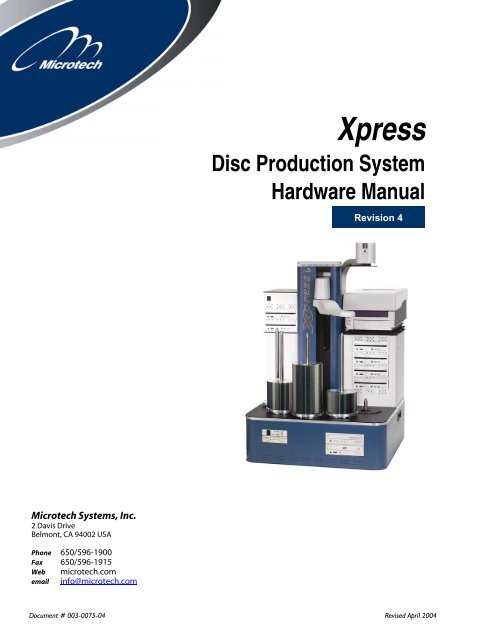
<strong>Xpress</strong><br />
Disc Production System<br />
Hardware Manual<br />
Revision 4<br />
Document # 003-0075-04 Revised April 2004
Regulatory Compliance<br />
Statements<br />
Notice for USA<br />
Federal Communications<br />
Commissions (FCC) Statement<br />
This equipment has been tested and found to comply with<br />
the radiated energy limits for a Class A digital device, in<br />
accordance with FCC CFR 47 Part 15 Rules and Regulations.<br />
(1) This device may not cause harmful<br />
interference, and (2) this device must accept any<br />
interference received, including interference that<br />
may cause undesired operation.<br />
Notice for Europe<br />
European Standards<br />
This equipment conforms to the EMC Directive<br />
(89/336/EEC) by compliance with the following European<br />
standards:<br />
EN 55022:1998 + A1:2000, CISPR 22:1997 + A1:2000 (Emissions):<br />
EN 50024:1998 + A1:2001, CISPR 24:1997 + A1:2001 (Immunity):<br />
EN 60950:2001 First Edition (Safety)
Contents<br />
Introduction ....................................................................................................................................... 1<br />
Introducing <strong>Xpress</strong>........................................................................................................................................2<br />
<strong>Xpress</strong>’s Parts .............................................................................................................................................................2<br />
<strong>Xpress</strong> Specifications................................................................................................................................................4<br />
Setting Up <strong>Xpress</strong>.............................................................................................................................. 5<br />
Disc Production Workspace....................................................................................................................................6<br />
Checking In Your Shipment ...................................................................................................................................7<br />
Unpacking <strong>Xpress</strong> .....................................................................................................................................................7<br />
<strong>Xpress</strong> Contents.........................................................................................................................................................8<br />
<strong>Xpress</strong> Assembly Procedures ..................................................................................................................................9<br />
<strong>Xpress</strong> Basics .................................................................................................................................... 13<br />
Powering Up <strong>Xpress</strong> ...............................................................................................................................................14<br />
The <strong>Xpress</strong> Desktop................................................................................................................................................15<br />
Checking the <strong>Xpress</strong> Software Configuration..................................................................................................16<br />
Initial System Calibration.....................................................................................................................................17<br />
Testing <strong>Xpress</strong> .........................................................................................................................................................19<br />
Placing Discs on Spindles.....................................................................................................................................20<br />
Shutting Down <strong>Xpress</strong> ...........................................................................................................................................21<br />
Calibrating <strong>Xpress</strong>........................................................................................................................... 23<br />
Calibrating <strong>Xpress</strong> ..................................................................................................................................................24<br />
Microtech Support..................................................................................................................................................25<br />
Index .................................................................................................................................................. 27<br />
Contents
Introduction
Hoist<br />
Reject Spindle<br />
Spindle #4<br />
Spindle #3<br />
Spindle #2<br />
Spindle #1<br />
Control Panel<br />
Floppy Disc Drive<br />
2 Introduction<br />
Introducing <strong>Xpress</strong><br />
This section will provide all the information you need to unpack, install,<br />
configure and use this system.<br />
<strong>Xpress</strong>’s Parts<br />
The following section shows and identifies all the important parts of<br />
your <strong>Xpress</strong>. These components will be referred to later in the manual;<br />
take a few moments to become familiar with them.<br />
The main parts of the <strong>Xpress</strong> production system are indicated below<br />
(front view).<br />
Elevator<br />
Digital Camera for<br />
(ImageAligner) option<br />
Disc Readers<br />
Light Shield/<br />
Camera Mount Disk<br />
Camera Support Boom<br />
Handhold<br />
Disc Printer<br />
Arm<br />
Printer Plate<br />
Drive Enclosure<br />
Disc Writers<br />
Base Unit (PC Enclosed)
Light Shield/Camera Mount Disc<br />
Camera Support Boom<br />
Drive Enclosure<br />
Base Unit<br />
Printer<br />
The elevator contains all automation elements including the hoist and<br />
the disc transport arm.<br />
The hoist is part of the elevator and raises/lowers the arm.<br />
The arm contains a disc gripper mechanism which holds discs during<br />
transport. The arm can rotate to reach all disc positions (spindles, disc<br />
writer drives and printer).<br />
The drive enclosure holds the disc writers and acts as a platform for the<br />
printer.<br />
The disc writers are the drives that write to blank discs. The exact<br />
number of writers installed (from 1 to 4) depends on your particular<br />
system. Writers can be CD-R, DVD-R, or a mix.<br />
The PC module contains the entire PC including disc readers, hard disk<br />
and power supply.<br />
The disc readers read master discs to be duplicated and other tasks.<br />
Typically, one reader will be a CD-ROM reader and the other will be a<br />
DVD-ROM drive.<br />
The disc spindles hold discs in various stages of processing. There are<br />
four full height spindles for holding blank and completed discs, and one<br />
shorter reject spindle. All spindles can be lifed off and on for easy disc<br />
handling.<br />
<strong>Xpress</strong> Back View<br />
Camera<br />
Elevator<br />
Printer Base Plate<br />
Introduction 3
Power Switch<br />
4 Introduction<br />
<strong>Xpress</strong>’s Control Panel<br />
The control panel on the front of <strong>Xpress</strong>’s base unit contains the power<br />
switch and several indicator lights.<br />
Besides the labeled indicator lights for power and the hard drive, there<br />
are four lights in a column, these lights are used to indicate the activity<br />
on drives or buses.<br />
<strong>Xpress</strong> Specifications<br />
• Dimensions:<br />
23” w X 23” d X 31” h [58mm x 58mm x 79mm]<br />
• Weight:<br />
System without printer: 135 lb. [61 kg]<br />
System with printer: 155 lb. [70 kg]<br />
Disc Drive<br />
Activity Lights<br />
Floppy Drive
Setting Up <strong>Xpress</strong>
Important Unpacking<br />
Information<br />
Be sure to save all packing<br />
material in case you need<br />
to move or ship your<br />
system.<br />
Microtech Systems will<br />
only accept merchandise<br />
returned in the original<br />
shipping container.<br />
6 Setting up <strong>Xpress</strong><br />
Disc Production Workspace<br />
The workspace for the <strong>Xpress</strong> disc production system should be in an<br />
environment free of dust and debris. Contamination can adversely affect<br />
production yield, degrade the quality of the discs produced, and reduce<br />
the life of the equipment. A typical office environment will provide the<br />
necessary cleanliness, temperature, and humidity control required to<br />
maximize system performance and service life.<br />
The workspace should have the following features:<br />
Sturdy workspace<br />
A working surface sturdy enough to support a total weight of<br />
200 lbs.<br />
Large workspace<br />
A large enough workspace: a recommended minimum of<br />
60” W x 48” D x 36” H, with 36” of clearance above.<br />
Electrical power<br />
The production system needs adequate power and enough power<br />
receptacles. Ensure that the power receptacles are properly grounded.<br />
The average power requirement for the entire system is 250 watts. The<br />
peak requirement may reach 400 watts. Microtech recommends using a<br />
surge protector and/or power conditioner for optimal setup.<br />
Adequate lighting<br />
There should be enough light both for operating the equipment and for<br />
examining the discs you produce and print. In addition, if the<br />
ImageAligner option is installed, adequate lighting for the digital camera<br />
to capture disc images is necessary (adequate light must be available<br />
even when the system is running jobs unattended after-hours). Direct<br />
sunlight or spotlights can adversely affect the robotic sensors of the<br />
<strong>Xpress</strong> as well as affecting the performance of the ImageAligner.<br />
Document storage<br />
Keep the documentation and software handy for future assistance,<br />
trouble shooting, etc.
Moving <strong>Xpress</strong>: Never pick<br />
up the main unit up by<br />
grasping the tower, as this<br />
can damage the unit.<br />
Always lift it using the<br />
handholds in the sides of<br />
the unit’s base<br />
Checking In Your Shipment<br />
Before unpacking <strong>Xpress</strong>:<br />
• Check shipping cartons against table below<br />
• Check for shipping damage<br />
The shipment should include the following number of cartons:<br />
SYSTEM CONFIGURATION NUMBER OF CARTONS<br />
No printer 3<br />
System with printer 4<br />
System with printer and<br />
IMAGEALIGNER option<br />
Please examine all of the shipping cartons. If any cartons are missing or<br />
damaged, notify the shipping carrier as soon as possible, then contact<br />
Microtech technical support at (650) 596-1900. Technical support is available<br />
Monday through Friday from 7:30 AM to 6:00 PM Pacific Time. Please<br />
contact us with any questions or problems during the unpacking,<br />
installation, and set up of the <strong>Xpress</strong> disc production system. If the<br />
shipping cartons are present and not damaged, start setting up a<br />
workspace for your production system.<br />
Unpacking <strong>Xpress</strong><br />
There are four basic <strong>Xpress</strong> configurations:<br />
1. Basic system only (no printer)<br />
2. Basic system with the Signature IV or Signature Pro (inkjet)<br />
printer<br />
3. Basic system with the Perfect Image (thermal transfer) printer<br />
4. Basic system with the Perfect Image (thermal transfer) printer and<br />
ImageAligner for printing on pre-printed discs<br />
A printer (and ImageAligner for printing on pre-printed discs) can be<br />
added to a basic system. Ask your dealer or sales representative about<br />
upgrade kits.<br />
All <strong>Xpress</strong> configurations are equipped with up to four CD-R or DVD-R<br />
writer drives and an additional 1 or 2 reader drives.<br />
Setting up <strong>Xpress</strong> 7<br />
5
Optional<br />
<strong>Xpress</strong> Contents<br />
8 Setting up <strong>Xpress</strong><br />
Box # 1 Contains<br />
Base Unit (housing PC Module)<br />
Keyboard<br />
Mouse<br />
Software Key<br />
Cables (<strong>Xpress</strong> Power Cord, and Serial Cable)<br />
Box #2 Contains<br />
Drive Enclosure<br />
Elevator<br />
Arm<br />
Printer Base Plate (w/ Printer Option Only)<br />
Box #3 Contains<br />
Monitor<br />
Cables<br />
Box #4 Contains<br />
Printer<br />
Cables (Data Cable, Power Cord, Control Cable {Signature Pro only})<br />
Box #5 Contains<br />
Digital Camera<br />
Camera Support Boom<br />
Light Shield/Camera Mount Disk<br />
Thumbscrews (3 Male and 1 Female)<br />
Camera Cable<br />
Calibration Disc<br />
During unpacking, visually inspect parts for dents, scratches or other<br />
damage. If any parts are damaged, call Microtech’s Customer<br />
Support Department at 650-596-1900 7:30 – 5:30 PST<br />
Microtech Systems will only accept merchandise returned in the<br />
original shipping container.
<strong>Xpress</strong> Assembly Procedures<br />
Base Unit<br />
1. Place Base Unit on Work surface.<br />
2. Set keyboard, mouse, Software Key, and cables aside for later<br />
connection.<br />
Drive Enclosure<br />
1. Remove thumbscrews (2) from the back of the Drive Enclosure –<br />
set aside.<br />
2. Remove back plate of Drive Enclosure.<br />
3. Place Drive Enclosure on top of Base Unit (back of enclosure fits<br />
flush with back of the Base Unit.)<br />
Caution – do not pinch any wires!<br />
4. Finger-tighten thumbscrews (6) inside Drive Enclosure to secure<br />
it to Base Unit.<br />
Elevator<br />
1. Place Elevator securely onto pegs on Base Unit (center of Drive<br />
enclosure).<br />
Caution – do not pinch any wires!<br />
2. Finger-tighten thumbscrews (2) inside Drive Enclosure to secure<br />
Handler Module to Drive Enclosure.<br />
Cabling<br />
1. Drive Power Cable (indicated by blue dot) – connect the Drive<br />
Power cable to port with the corresponding blue dot.<br />
2. Fan Power Cable (indicated by yellow dot) – connect the Fan<br />
Power Cable to port with the corresponding yellow dot.<br />
3. Control Cable (indicated by red dot) –- connect the Control<br />
Cable to port with the corresponding red dot.<br />
4. Connect two ribbon cables from under fans to the Arm located<br />
on the Elevator – Undo the twist-tie holding them together –<br />
push into connectors firmly until connector locks.<br />
5. Connect Drive Cables (4)<br />
6. Replace back of Drive Enclosure.<br />
7. Replace and tighten thumbscrews.<br />
Setting up <strong>Xpress</strong> 9
10 Setting up <strong>Xpress</strong><br />
Arm to Elevator<br />
1. Remove threaded knob from underside of Hoist (on Elevator).<br />
2. Line up holes on rear end of Arm with pins on Hoist.<br />
3. Replace threaded knob and finger tighten to secure Arm to<br />
Hoist.<br />
4. Connect Arm to Hoist with small “phone” cord.<br />
5. Place long Spindles on locations 1 – 4.<br />
6. Place short Spindle on location 5.<br />
7. Replace packing material in shipping box and store for<br />
moving/shipping.<br />
Disc Printer Option<br />
1. Slide Printer Base Plate (from Box #2) into slots on top of drive<br />
enclosure.<br />
2. Finger-tighten two thumbscrews to secure Printer Base Plate to<br />
Drive Enclosure.<br />
3. Place Printer onto pegs on surface of Printer Base Plate.<br />
Printer Connection<br />
Perfect Image<br />
1. Connect data cable between port on back of Printer and COM1<br />
on back of <strong>Xpress</strong> Base Unit.<br />
2. Connect Printer Power Cord to port on back of Printer, plug<br />
opposite end into standard electrical outlet.<br />
3. Install Software Key into any USB port on back of <strong>Xpress</strong> Base<br />
Unit.<br />
Note: If using ImageAligner Option, insure that Software Key is installed<br />
in Parallel Port on back of <strong>Xpress</strong> Base Unit.<br />
Signature Pro<br />
1. Connect Data Cable between port on back of Printer and port on<br />
back of <strong>Xpress</strong> Base Unit.<br />
2. Connect Control Cable between port on back of Printer and port<br />
on back of Drive Enclosure.<br />
3. Connect Printer Power Cord to port on back of Printer, plug into<br />
standard electrical outlet.<br />
4. Install Software Key into any USB port on back of <strong>Xpress</strong> Base<br />
Unit.<br />
PRINTER IS READY FOR INITIAL TESTING
Installing ImageAligner Option<br />
1. Place Camera Support Boom on top of Printer Base Plate behind<br />
Elevator.<br />
2. Tighten attached knobs (3) to secure Camera Support Boom to<br />
threaded holes in Printer Base Plate.<br />
3. Line up pegs (2) and threaded rod on top of Light<br />
Shield/Camera Mount Disk with holes on bottom of Camera<br />
Support Boom.<br />
4. Finger tighten knob onto threaded rod to secure Light<br />
Shield/Camera Mount Disk to Camera Support Boom.<br />
5. Open Camera Lens.<br />
6. Attach Camera to Mount by finger tightening attached<br />
thumbscrew.<br />
7. Connect Camera Cable between port on top of Camera and port<br />
on back of <strong>Xpress</strong> Base Unit.<br />
8. Secure Camera Cable to Camera Support Boom using attached<br />
cord clips<br />
PRINTER IS READY FOR INITIAL TESTING<br />
Additional Cables<br />
1. Connect <strong>Xpress</strong> Main Power Cord to port on back of Base Unit,<br />
plug into standard 110v electrical outlet.<br />
2. Install Software Key into any USB port on back of Base Unit.<br />
Note: With ImageAligner option, install Software Key into Parallel Port on<br />
back of Base Unit.<br />
3. Connect Serial Cable from back of Base Unit in COM2 to back of<br />
Drive Enclosure.<br />
XPRESS IS READY FOR INITIAL TESTING<br />
Setting up <strong>Xpress</strong> 11
<strong>Xpress</strong> Basics
14 <strong>Xpress</strong> Basics<br />
Once <strong>Xpress</strong> is set up, test it to make sure everything is operating<br />
properly. This chapter covers two quick test procedures. The first is an<br />
automated test, that confirms that the system mechanics are working,<br />
and that discs can be picked up, dropped and moved around correctly.<br />
The second part of the test actually makes disc copies to verify that the<br />
system’s electronics and disc writer drives are working properly.<br />
Powering Up <strong>Xpress</strong><br />
• Press and release the power switch (located on the control panel on<br />
the front; see page 3 for its location.)<br />
• <strong>Xpress</strong> is a Microsoft Windows-based system that needs to go<br />
through its boot-up process. As shipped from Microtech, each<br />
system is set up to log you in as the user Administrator, with no<br />
password (leave the password field blank in the login dialog). Once<br />
the system is set up and running on your network, create a new user<br />
account and make a practice of logging in as that user.<br />
After your login information has been validated, the Windows desktop<br />
will appear, and you may begin using the system.
The <strong>Xpress</strong> Desktop<br />
Important icons and other parts of the desktop<br />
The MyDisc icon<br />
Starts the standard MyDisc program used to create master images of<br />
custom discs from which to make copies. Using MyDisc for making discs<br />
is covered in the software manual.<br />
The ImageMaker EZ icon<br />
Starts the disc duplication program used to make disc copies.<br />
Instructions for using ImageMaker EZ are covered in the software<br />
manual.<br />
The DiscPrint icon<br />
Starts the DiscPrint program, the “stand-alone” version of the<br />
ImageMaker EZ disc layout editor, used to create and modify disc<br />
printing layouts.<br />
The ImageMaker MJ (“Classic”) icon<br />
Starts the optional ImageMaker MJ software for disc duplication. Please<br />
refer to the software manual.<br />
The <strong>Xpress</strong> Calibration icon<br />
Starts the <strong>Xpress</strong> calibration utility used for calibrating the system.<br />
The CD-REMOTE icon<br />
Starts the CD-REMOTE background process and is only necessary should<br />
you need to restart the process. CD-REMOTE starts automatically when it<br />
is needed.<br />
The Windows taskbar<br />
When a program is started (e.g. MyDisc), a button for that program will<br />
appear in the taskbar (located at the bottom of the deskstop screen). If a<br />
program has been minimized (still running, but not displayed on screen),<br />
or if it has disappeared behind another program’s window, clicking its<br />
taskbar button will make it appear on screen.<br />
<strong>Xpress</strong> Basics 15
See the software manual<br />
for a complete explanation<br />
of all the ImageMaker<br />
configuration items.<br />
16 <strong>Xpress</strong> Basics<br />
Checking the <strong>Xpress</strong><br />
Software Configuration<br />
Before performing the initial test on the production system, check the<br />
system configuration to ensure that certain items are set properly. This is<br />
done through the ImageMaker (software) configuration utility.<br />
Start the configuration utility.<br />
Click the Windows Start button, located on the lower-left corner of the<br />
desktop. From the menu that pops up, work through the submenus to<br />
select Programs�ImageMaker�Configure ImageMaker. The<br />
configuration dialog, shown below, will open.<br />
Check the following configuration items to make sure they’re set<br />
correctly:<br />
If a printer is installed, it must be identified<br />
Select the printer name in the field labeled My disc printer is …, and set<br />
the port in the following field accordingly. (If there’s no printer, ignore<br />
this setting.)<br />
IF YOUR PRINTER IS A SELECT THIS TYPE ON THIS PORT<br />
Perfect Image (black-only or color thermal transfer) Rimage Printer COM1<br />
Signature IV (color inkjet) CD Color Printer IV LPT1<br />
Signature Pro (color inkjet) CD Color Printer Pro LPT1<br />
Identify the type of ImageAutomator system<br />
In the field labeled The ImageAutomator is a model …, select <strong>Xpress</strong>.<br />
• Save any changes made. If any changes to the configuration have<br />
been made click the Update button before closing the utility. If no<br />
changes have been made, click Close.
Initial System Calibration<br />
One of the programs included with the system is a calibration utility.<br />
This utility includes a quick initial system test for checking the basic<br />
disc-transporting functions. Follow the procedure below to run this test.<br />
Prepare for the checkout procedure<br />
Place a few discs on spindle 3. Start the calibration utility program by<br />
double-clicking the program’s desktop icon, shown here to the left. The<br />
calibration utility’s window will open (shown below).<br />
Set up and run the quick test once<br />
The test will simulate a single disc being copied. Click the single test<br />
cycle button to start the test.<br />
1. A disc will be picked up from spindle 3.<br />
2. The top disc writer drive tray will open and the disc will be placed<br />
into the tray.<br />
3. The disc writer drive tray will close, then open.<br />
4. The disc will be picked up from the disc writer, and the drive tray<br />
will close.<br />
Note: If a printer is installed, the printer tray will open, and the disc will<br />
be placed in the tray: The printer tray will close, and the disc writer drive<br />
tray will close. The printer tray will then open, and the disc will be<br />
picked up from the printer tray, and the printer tray will close.<br />
5. If no printer is installed, the disc will be picked up from the disc<br />
writer drive tray and dropped on spindle 4.<br />
<strong>Xpress</strong> Basics 17
18 <strong>Xpress</strong> Basics<br />
Observe the following carefully during quick test<br />
• Arm centers on spindle<br />
• Disc is dropped in center of drive writer tray<br />
• Disc is dropped onto output spindle<br />
If Printer is installed<br />
• Disc is dropped in center of printer tray<br />
• Disc is dropped directly onto output spindle<br />
If the single initial test fails, run the continuous test to locate the<br />
problem—Make sure there are several discs on spindle 3. Click the<br />
continuous test button at the lower right to run the same test<br />
continuously.<br />
Disc handling problems are not always repeatable. Accurate calibration<br />
is important to achieve reliable operation. It is recommended that you<br />
run the continuous test through several hundred discs to insure proper<br />
calibration.<br />
After starting the test, this button name will automatically change to<br />
Stop Continuous. To stop the test, click this button.<br />
If the problem recurs, calibration (adjustment) of the system is necessary.<br />
(See the following chapter, Calibrating <strong>Xpress</strong> for complete<br />
instructions.)
Testing <strong>Xpress</strong><br />
After the system has passed the previous test, complete the testing<br />
process by actually making disc copies. To do this use the disc<br />
duplication program, ImageMaker EZ using the following procedure:<br />
Start the disc duplication program<br />
Click the program’s desktop icon. The duplication program will open,<br />
and the main window will appear (see illustration below).<br />
Place several blank discs on spindle 3<br />
The third spindle from the left. Refer to the diagram on page 2.<br />
Click the button to make disc copies from a<br />
pre-existing disc image<br />
The window will change when this is done, and some additional input<br />
fields will appear.<br />
Select the disc image to use to make copies from.<br />
Find the field labeled Disc Name near the top. Click the arrow at the<br />
right of this field to open a list box of available images. There are two<br />
images included with every <strong>Xpress</strong> system, one for systems with a<br />
printer installed and one for systems without a printer. (The one for<br />
printer-equipped systems will also print the disc copies.) Click on your<br />
system type to select it.<br />
Click Start to begin the test<br />
If the quantity has not been changed, only one copy will be made. A<br />
blank disc should be picked up from spindle 3 and delivered to one of<br />
the disc writer drives. After the disc is “burned” (and printed if a printer<br />
is installed), it will be picked up from the drive and placed on spindle 4.<br />
<strong>Xpress</strong> Basics 19
Spindle #1<br />
Tertiary Input Spindle (3 rd<br />
200 discs)<br />
Spindle #2<br />
Secondary Input Spindle<br />
(2 nd 200 discs)<br />
20 <strong>Xpress</strong> Basics<br />
Placing Discs on Spindles<br />
As an automated disc production system, <strong>Xpress</strong> transports discs to<br />
various processing stations internally. The operator’s only physical task<br />
is to load blank discs for processing on the input spindle(s) and remove<br />
finished discs from the output spindle(s).<br />
The diagram below shows the location and function of the various<br />
spindles, viewed from above.<br />
Spindle #3<br />
Primary Input Spindle (1 st<br />
200 discs)<br />
Spindle #5<br />
Reject Spindle<br />
Spindle #4<br />
Output Spindle<br />
Each spindle holds 200 discs. To process a total of 600 discs with only 4<br />
spindles, some spindles must be used to hold both blank and written<br />
media (not at the same time). To start, blank media are loaded on<br />
spindles 1, 2 and 3 and spindle 4 is left empty. Blank discs will be<br />
retrieved from spindle 3 and completed discs will be placed on spindle 4.<br />
When all discs have been removed from spindle 3, the whole operation<br />
shifts by one spindle and blank discs will be retrieved from spindle 2 and<br />
completed discs will be placed on (the now empty) spindle 3. When all<br />
discs on spindle 2 have been used, the operation will shift one more time<br />
and blank discs will be retrieved from spindle 1 and completed discs will<br />
be placed on spindle 2. When all 600 discs have completed, there will be<br />
discs on spindles 2, 3 and 4 and nothing on spindle 1.<br />
When the disc production software is started, the production system<br />
automatically resets itself to take discs from spindle 3 and places finished<br />
discs on spindle 4. This is true even if the system was previously taking<br />
discs from spindle 2 or spindle 1.<br />
Whenever the disc production software is started, blank discs must be<br />
loaded on spindles 3, 2 and 1 and spindle 4 must be empty.
CAUTION: Do not shut<br />
down the system if there<br />
are any production jobs<br />
running on it. It may not<br />
be obvious if a job is<br />
running, since a job could<br />
be in the pre-mastering<br />
phase. Use the CD-REMOTE<br />
Management Center to<br />
check the status of current<br />
jobs (see software manual<br />
for details).<br />
Shutting Down <strong>Xpress</strong><br />
When the job completes, please follow the standard Windows shut down<br />
procedures.<br />
<strong>Xpress</strong> Basics 21
Calibrating <strong>Xpress</strong>
Calibrating <strong>Xpress</strong><br />
24 Calibrating <strong>Xpress</strong><br />
To work properly, <strong>Xpress</strong> needs to be correctly calibrated. <strong>Xpress</strong> is<br />
calibrated at the factory and should not need recalibration. Improper<br />
handling during shipping may make this step necessary. If discs are not<br />
picked up from the input spindles, are being dropped off the trays or<br />
output spindles or are going into drive or printer trays cockeyed, the<br />
system must be recalibrated.<br />
Calibration means making adjustments to the disc production system so<br />
the operation runs smoothly.<br />
Prepare for the calibration procedure<br />
Place a few discs on spindles 1, 2 and 3. Start the calibration utility<br />
program by double-clicking its desktop icon. The calibration utility’s<br />
window will open.<br />
Adjust the spindle calibrations<br />
Click the Calibrate Position button and click on the button for the<br />
spindle you wish to calibrate (S1 for example). The disc transport arm<br />
will move over to the top of the spindle, move down close to the top of<br />
the spindle and then stop.<br />
If the arm is not centered exactly over the spindle, the calibration of the<br />
spindle must be corrected. Use the two arrow buttons and to “bump” the<br />
position of the arm counter clockwise or clockwise respectively. When<br />
the arm is centered, click the Save button to accept the change. Recheck<br />
the alignment by repeating this step. Click the Cancel button if no<br />
change is necessary.<br />
Repeat this step for spindles 1-4.<br />
Adjust the calibration of the reject spindle<br />
Click the Calibrate Position button and then the Rej button. A message<br />
warning you to close all printer and drive trays will be displayed. Click<br />
OK when all trays are closed. The disc transport arm will move over and<br />
down to the reject spindle. As above, make any necessary adjustments<br />
and click the Save button to accept the new position.<br />
Adjust the drive calibration<br />
There is no separate calibration for drives 1-4. Only one of the stations<br />
(D1-D4) must be calibrated. Have at least one disc on spindle 3 and one<br />
of the drive trays open. Click the Calibrate Position button and the D1<br />
button. The disc transport arm will pick up a disc from spindle 3 and<br />
move it over to the drive. Once it senses the drive tray, the arm will<br />
move back and stop above the drive tray.<br />
Check that the disc is properly centered above the drive tray and that it<br />
is clear of the front of the drive. Drive trays are slightly beveled so it is<br />
okay if the disc is a bit forward of center. When the position of the disc is<br />
correct, click on the Save button.
Microtech Support<br />
If you are having problems with your <strong>Xpress</strong>, before calling Microtech<br />
Systems support line please check the following:<br />
1. Check all external connections<br />
2. Check for good power<br />
3. Make sure your system is on a sturdy and level surface<br />
4. Check the tightness of the thumbscrews that hold the main<br />
assemblies together<br />
If none of these solutions solve the problem, please have the following<br />
information available before calling Microtech Systems support.<br />
1. Serial number (3-4 digit number located on the back of the system or<br />
under the keyboard),<br />
2. Detailed description of problem(s) experienced.<br />
Microtech Systems<br />
2 Davis Drive<br />
Belmont, CA 94002<br />
650-596-1900<br />
Hours: 7:30 a.m. – 5:30 p.m. PST<br />
support@microtech.com<br />
www.microtech.com<br />
Calibrating <strong>Xpress</strong> 25
Assembly Procedures................................................ 9<br />
Control Panel.............................................................. 4<br />
Desktop Icons ........................................................... 15<br />
Initial System Calibration ....................................... 17<br />
Initial System Checkout .......................................... 19<br />
Microtech Support ................................................... 25<br />
Placing Discs on Spindles ....................................... 20<br />
Shutting Down the System..................................... 21<br />
Index<br />
Software Configuration ...........................................16<br />
Specifications ..............................................................4<br />
Starting the System ..................................................14<br />
System Calibration ...................................................24<br />
Systems Parts ..............................................................2<br />
Windows NT<br />
starting Windows .................................................14<br />
<strong>Xpress</strong> Parts.................................................................8<br />
Index 27