Large Diameter Stepped Coupling
Large Diameter Stepped Coupling
Large Diameter Stepped Coupling

Create successful ePaper yourself
Turn your PDF publications into a flip-book with our unique Google optimized e-Paper software.
CI/SfB<br />
It6<br />
VJ102<br />
May 1999<br />
DIMENSIONAL DATA
IMPORTANT NOTICE<br />
The technical, performance data, specifications, dimensions and all other information published in the Design Data section supersede all previously<br />
published information. All data contained herein is subject to change without notice.<br />
The information given in the following pages is intended as a general guide to the proper design and installation of practical piping systems using Viking<br />
Johnson products, and is not intended as a substitute for competent, professional advice, which should always be sought in the design of any piping<br />
system. Good piping practice should always prevail and recommended design pressures, temperatures, tolerances and loads should never be exceeded.<br />
Special conditions often exist for which the information given here is not specifically suited and specialist engineering advice should be obtained. As with<br />
any other piping system, the specific advantages and limitations of Viking Johnson products should be considered when designing a system using Viking<br />
Johnson products. The suggestions made here do not set out to give specific solutions to actual installation problems but to give ideas on which to base<br />
your own unique solutions.<br />
While every effort has been made to ensure its accuracy, Viking Johnson make no express or implied warranty of any kind in respect of the information<br />
contained in this brochure or the materials referred to herein. Any person making use of the information contained here does so entirely at their own risk<br />
and assumes any and all liability resulting from such use.<br />
The information contained within this section applies specifically to Viking Johnson products only, and is not intended to apply to any other bolted sleeve<br />
type coupling product.<br />
© 1999 by Viking Johnson. Printed in the United Kingdom. No part of this booklet may be reproduced, stored or transmitted, in any form or by any means,<br />
electronic, mechanical, photocopying, recording or otherwise, without prior permission of Viking Johnson.<br />
© Viking Johnson 1999 Tel: +44 (0)1462 443322 Fax: +44 (0)1462 443311<br />
e-mail: info@vikingjohnson.co.uk
Contents<br />
Viking Johnson<br />
GPS<br />
<strong>Coupling</strong>s ..................................................................................................5<br />
MaxiFit........................................................................................6<br />
AquaGrip ....................................................................................7<br />
FlexLock.....................................................................................7<br />
QuickFit...................................................................................8-9<br />
<strong>Large</strong> <strong>Diameter</strong> .....................................................................9-13<br />
Juno..........................................................................................13<br />
<strong>Stepped</strong> <strong>Coupling</strong>s..............................................................................14<br />
MaxiStep ..................................................................................15<br />
AquaGrip ..................................................................................16<br />
<strong>Large</strong> <strong>Diameter</strong> ...................................................................16-17<br />
Juno..........................................................................................18<br />
Flange Adaptors...................................................................................19<br />
MaxiDaptor .........................................................................20-21<br />
AquaGrip.............................................................................21-23<br />
FlexLock...................................................................................23<br />
QuickFit...............................................................................24-25<br />
<strong>Large</strong> <strong>Diameter</strong> ...................................................................25-33<br />
Repair and Tapping Products .........................................................34<br />
EasiClamp & EasiTap...............................................................35<br />
<strong>Large</strong> <strong>Diameter</strong> EasiClamp & EasiTap ....................................35<br />
Universal EasiTee.....................................................................36<br />
HandiClamp .............................................................................37<br />
<strong>Large</strong> <strong>Diameter</strong> Under Pressure Tees.....................................38<br />
EasiCollar .................................................................................38<br />
Other Products<br />
Dismantling Joints..............................................................39-41<br />
LinerGrip...................................................................................42<br />
Juno Adaptors .........................................................................42<br />
Supplementary Information<br />
Working Pressure Table...........................................................43<br />
Corrosion Protection ...............................................................44<br />
Summary of Gaskets ...............................................................45<br />
Chemical Resistance Chart.....................................................46<br />
Flange Comparison Chart .......................................................47<br />
O.D. Conversion Chart .......................................................48-49<br />
© Viking Johnson 1999 Tel: +44 (0)1462 443322 Fax: +44 (0)1462 443311<br />
e-mail: info@vikingjohnson.co.uk
Introduction<br />
Viking Johnson<br />
GPS<br />
The Viking Johnson System for<br />
joining plain-ended pipes was first<br />
introduced to the market in 1931 and is<br />
now recognised as being second to<br />
none in reliability and quality.<br />
This brochure provides full<br />
dimensions and material specifications<br />
for the various Viking Johnson<br />
products. Should you require any<br />
additional information, please contact<br />
the Marketing Department.<br />
The Viking Johnson system is suitable<br />
for an enormous range of pipework<br />
applications and it is therefore<br />
impossible to give a comprehensive list<br />
of potential uses. In general terms, the<br />
system is suitable for virtually any<br />
pipeline, above or below ground level,<br />
working within the following typical<br />
parameters:<br />
Working Pressure - up to 100 bar<br />
(1450psi), according to size.<br />
Temperature - limited by gasket grade<br />
used, but within the range - 60°C to<br />
200°C. (-75°F to 390°F)<br />
Suitable for - water, gas, oil,<br />
petrochemicals, sewage, powdered<br />
solids, granular solids, air.<br />
Location - above or below ground.<br />
Backed by many years of design and<br />
manufacturing experience, Viking<br />
Johnson are confident that the Viking<br />
Johnson System is a complete and<br />
cost effective answer to almost all<br />
pipeline installation problems.<br />
Compare the following benefits with<br />
those offered by alternative pipe<br />
jointing systems:<br />
• ISO 9001 certification is proof of our<br />
exacting quality standards.<br />
• Exclusive Viking Johnson gaskets,<br />
moulded in our own plant to exacting<br />
specifications, assure perfect lifetime<br />
sealing, meeting all relevant<br />
Standards.<br />
• Size range extends from 15mm (0.5")<br />
to more than 5000mm (200").<br />
• The Viking Johnson System is<br />
designed for plain-ended pipes<br />
eliminating threading, bevelling,<br />
welding or flanging.<br />
• The system can joint most types of<br />
pipes, valves or meters.<br />
• By specifying Viking Johnson,<br />
installation delays caused by<br />
adverse weather conditions are<br />
overcome, particularly relevant to PE<br />
installation.<br />
• You can rely on Viking Johnson<br />
products. Their dependability has<br />
been demonstrated for over 60<br />
years, in all conditions of service.<br />
• On-site jointing equipment, with<br />
Viking Johnson all you need is a<br />
spanner and torque wrench.<br />
• The simplicity of our design assures<br />
you of couplings which will assemble<br />
quickly, easily and accurately every<br />
time. Company representatives are<br />
available to offer technical advice to<br />
the installer.<br />
• As a mechanical jointing system it<br />
can eliminate the need for specialist<br />
labour or on-site fabrication.<br />
• Viking Johnson couplings are<br />
protected for life against corrosion<br />
with a range of specialised coatings.<br />
Please state coating required when<br />
ordering.<br />
• Viking Johnson has over 80 agents<br />
and Distributors worldwide, in<br />
addition to an exclusive Distributor<br />
network throughout the UK.<br />
Unless otherwise stated, all<br />
dimensions are in mm.<br />
The working pressure quoted in Bar<br />
is that of the coupling/flange<br />
adaptor etc. and not that of the<br />
pipe. Working pressure is generally<br />
2/3rds of the test pressure.<br />
Glossary of Terms<br />
The following abbreviations are used in this brochure:-<br />
AC<br />
- Asbestos cement.<br />
4<br />
OD<br />
NB<br />
DN<br />
PN<br />
CI<br />
DI<br />
PE<br />
MDPE<br />
- Pipe outside diameter.<br />
- Nominal bore.<br />
- Nominal diameter, in millimetres.<br />
- Nominal pressure, in bar<br />
(1 bar = 0.1 MPa = 0.1 N/mm 2 ≈ 14.5 lbf/in 2 ).<br />
- Grey cast iron.<br />
- Ductile iron.<br />
- Polyethylene.<br />
- Medium density polyethylene (PE80)<br />
GRP<br />
uPVC<br />
PVC-u<br />
ABS<br />
EPDM<br />
NBR<br />
WBS<br />
PCD<br />
- Glass reinforced plastics.<br />
- Unplasticised polyvinyl chloride.<br />
- Metric uPVC pipe (including molecular oriented and impact<br />
modified).<br />
- Acrylonitrile butadiene styrene.<br />
- Ethylene propylene diene monomer.<br />
- Nitrile butadiene rubber.<br />
- UK Water Research Centre, Water Byelaws Scheme Approval.<br />
- Pitch circle diameter.<br />
HPPE<br />
- High performance polyethylene (PE100)<br />
© Viking Johnson 1999 Tel: +44 (0)1462 443322 Fax: +44 (0)1462 443311<br />
e-mail: info@vikingjohnson.co.uk
<strong>Coupling</strong>s<br />
Viking Johnson<br />
GPS<br />
MaxiFit <strong>Coupling</strong><br />
AquaGrip <strong>Coupling</strong><br />
FlexLock <strong>Coupling</strong><br />
Standard <strong>Coupling</strong><br />
BOLT TORQUE TABLE FOR COUPLINGS<br />
ALL PRODUCTS EXCEPT<br />
PRODUCT<br />
AQUAGRIP<br />
AQUAGRIP<br />
COATING BLACK RILSAN BLACK RILSAN BLUE SHERAPLEX<br />
BOLT SIZE TORQUE TORQUE TORQUE<br />
lbf.ft Nm lbf.ft Nm lbf.ft Nm<br />
M12 40 - 50 55 - 65 55-60 70-75 40-50 55-65<br />
M16 70 - 80 95 - 110 - - - -<br />
FULL BOLT TORQUE MUST BE ACHIEVED TO ENSURE THAT COUPLING / FLANGE ADAPTOR etc.<br />
FUNCTIONS TO ITS DESIGNED PERFORMANCE STANDARDS.<br />
© Viking Johnson 1999 Tel: +44 (0)1462 443322 Fax: +44 (0)1462 443311<br />
e-mail: info@vikingjohnson.co.uk<br />
5
MaxiFit <strong>Coupling</strong>s<br />
Viking Johnson<br />
GPS<br />
Tolerance Bolts Dimensions Setting Weight<br />
Min Max Gasket No. - Dia x Length A B C Gap (Kg)<br />
(x)<br />
47.9 59.5 1637 2 - M12 x 175 149.5 140 178 20 3.1<br />
59.5 72.0 1613 3 - M12 x 175 164.0 140 178 20 2.6<br />
72.2 85.0 1614 3 - M12 x 175 177.0 140 178 20 2.9<br />
88.1 102.4 1615 4 - M12 x 175 197.5 140 178 20 3.7<br />
107.2 115.1 1620 4 - M12 x 175 224.5 140 178 20 4.6<br />
109.6 127.8 1759 4 - M12 x 175 211.5 140 178 20 4.1<br />
118.0 131.5 1616 4 - M12 x 175 226.0 140 178 20 4.3<br />
132.2 146.0 1635 4 - M12 x 175 248.5 140 178 20 5.3<br />
138.9 153.2 1633 4 - M12 x 175 248.5 140 178 20 4.8<br />
141.9 156.2 1633 4 - M12 x 175 248.5 140 178 20 5.6<br />
158.2 169.9 1621 4 - M12 x 175 279.0 140 178 20 6.6<br />
159.2 181.6 1760 4 - M12 x 195 274.0 165 203 20 6.2<br />
192.9 209.0 1758 4 - M12 x 215 321.0 185 223 20 8.5<br />
218.1 235.0 1757 4 - M12 x 215 306.5 185 223 20 9.2<br />
230.0 247.0 1756 5 - M12 x 215 357.0 185 223 20 15.6<br />
250.0 267.0 1655 6 - M12 x 215 379.0 185 223 20 16.3<br />
272.0 289.0 1656 6 - M12 x 215 400.5 185 223 20 17.5<br />
322.9 339.4 1657 8 - M12 x 215 451.5 185 223 25 20.1<br />
332.0 349.0 1658 8 - M12 x 215 461.0 185 223 25 20.6<br />
351.0 368.0 6002 8 - M12 x 340 478.0 310 348 40 32.4<br />
374.5 391.5 1659 8 - M12 x 340 501.5 310 348 40 34.2<br />
386.0 403.0 6035 8 - M12 x 340 513.0 310 348 40 35.2<br />
394.3 411.3 1766 8 - M12 x 340 521.5 310 348 40 35.6<br />
404.8 421.8 1767 8 - M12 x 340 532.0 310 348 40 36.4<br />
412.0 429.0 6023 10 - M12 x 340 539.0 310 348 40 37.6<br />
418.2 435.2 1784 8 - M12 x 340 545.0 310 348 40 37.6<br />
425.0 442.0 1662 8 - M12 x 340 552.0 310 348 40 38.2<br />
434.5 451.5 1768 10 - M12 x 340 561.5 310 348 40 39.6<br />
439.0 456.0 6036 10 - M12 x 340 566.0 310 348 40 40.2<br />
455.0 472.0 6003 10 - M12 x 340 582.0 310 348 40 41.2<br />
476.0 493.0 1770 10 - M12 x 340 603.0 310 348 40 43.0<br />
487.0 504.3 1771 10 - M12 x 340 614.5 310 348 40 43.9<br />
492.0 509.0 6037 10 - M12 x 340 619.0 310 348 40 44.3<br />
501.9 518.9 1772 10 - M12 x 340 629.0 310 348 40 44.5<br />
515.0 532.0 6024 12 - M12 x 340 642.0 310 348 40 46.7<br />
527.0 544.0 1773 12 - M12 x 340 654.0 310 348 40 47.7<br />
540.1 557.1 1774 10 - M12 x 340 667.0 310 348 40 47.8<br />
546.0 563.0 6038 12 - M12 x 340 673.0 310 348 40 48.5<br />
555.3 572.3 1775 12 - M12 x 340 682.5 310 348 40 49.8<br />
565.0 582.0 1776 12 - M12 x 340 692.0 310 348 40 51.2<br />
593.0 610.0 6021 12 - M12 x 340 720.0 310 348 40 52.4<br />
601.0 618.0 6020 12 - M12 x 340 728.0 310 348 40 52.9<br />
613.0 630.0 6019 12 - M12 x 340 740.0 310 348 40 53.8<br />
618.0 635.0 6025 12 - M12 x 340 745.0 310 348 40 54.6<br />
630.0 647.0 1778 14 - M12 x 340 757.0 310 348 40 56.1<br />
654.0 671.0 6039 14 - M12 x 340 781.0 310 348 40 57.9<br />
662.0 679.0 1780 14 - M12 x 340 789.0 310 348 40 58.4<br />
678.0 695.0 6005 14 - M12 x 340 802.0 310 348 40 59.0<br />
MaxiFitXtra <strong>Coupling</strong>s<br />
6<br />
Tolerance Bolts Dimensions Setting Weight<br />
Min Max Gasket No. - Dia x Length A B C Gap (Kg)<br />
(x)<br />
109.6 127.8 1759 4 - M12 x 275 215.5 245 283 20 5.3<br />
159.2 181.6 1760 4 - M12 x 275 274.0 245 283 20 7.5<br />
218.1 235.0 1757 4 - M12 x 275 320.5 245 283 20 11.6<br />
Viking Johnson can manufacture <strong>Coupling</strong> products to virtually any diameter. Those shown are for information. For sizes or diameters not shown, please request further information.<br />
© Viking Johnson 1999 Tel: +44 (0)1462 443322 Fax: +44 (0)1462 443311<br />
e-mail: info@vikingjohnson.co.uk
AquaGrip <strong>Coupling</strong>s<br />
Viking Johnson<br />
GPS<br />
Pipe SDR No. of Gripper Segments Bolts Dimensions Setting Gap Weight<br />
O.D. Rating Gasket Full Half No. - Dia x Length A B C (x) (kg)<br />
(mm) Min Max<br />
63 11 6001 20 2 2 - M12 x 195 144.0 180.0 203 20 40 2.4<br />
90 11 1785 28 - 4 - M12 x 195 167.5 180.0 203 20 40 3.7<br />
90 17/17.6 1785 28 - 4 - M12 x 195 167.5 180.0 203 20 40 3.8<br />
110 11 1786 34 - 4 - M12 x 195 188.0 180.0 203 20 40 5.3<br />
110 17/17.6 1786 34 - 4 - M12 x 195 188.0 180.0 203 20 40 5.4<br />
125 11 1787 38 - 6 - M12 x 195 203.0 180.0 203 20 40 5.7<br />
125 17/17.6 1787 38 - 6 - M12 x 195 203.0 180.0 203 20 40 5.8<br />
160 11 1788 48 - 8 - M12 x 215 240.0 200.0 223 20 40 8.8<br />
160 17/17.6 1788 48 - 8 - M12 x 215 240.0 200.0 223 20 40 9.0<br />
160 26 1788 48 - 8 - M12 x 215 240.0 200.0 223 20 40 9.8<br />
180 11 1789 52 - 8 - M12 x 215 257.5 200.0 223 20 40 9.5<br />
180 17/17.6 1789 52 - 8 - M12 x 215 257.5 200.0 223 20 40 9.8<br />
FlexLock <strong>Coupling</strong>s for Steel Pipe<br />
Pipe Pipe Bolts No. of Dimensions Setting Gap Weight Pressure<br />
Nominal O.D. Gasket No.- Dia x Length Inserts A B C (x) (kg) (bar)<br />
Min Max Working Test<br />
DN50/2" 60.3 1375 2 - M12 x 145 3 135.0 127 157 20 40 2.7 16 24<br />
DN65/2.5" 76.1 1394 2 - M12 x 160 3 151.5 140 170 20 40 3.2 16 24<br />
DN80/3" 88.9 1382 4 - M12 x 160 4 163.0 140 170 20 40 4.2 16 24<br />
DN100/4" 114.3 1367 4 - M12 x 175 4 194.5 153 183 20 40 6.1 16 24<br />
DN150/6" 165.1 1369 6 - M12 x 175 7 253.5 153 183 20 40 9.2 16 24<br />
DN150/6" 168.3 1369 6 - M12 x 175 7 255.5 153 183 20 40 9.2 16 24<br />
DN200/8" 219.1 1370 8 - M12 x 175 12 309.5 153 183 20 40 11.9 16 24<br />
DN250/10" 273.0 1737 12 - M16 x 275 15 376.0 256 286 20 40 32.1 10 15<br />
FlexLock <strong>Coupling</strong>s for Metric Ductile Iron Pipe<br />
Pipe Pipe Bolts No. of Dimensions Setting Gap Weight Pressure<br />
Nominal O.D. Gasket No. - Dia x Length Inserts A B C (x) (kg) (bar)<br />
Min Max Working Test<br />
DN80/3" 98.0 1630 4 - M12 x 195 4 181.0 173 203 20 40 5.21 16 24<br />
DN100/4" 118.0 1618 4 - M12 x 195 4 200.0 173 203 20 40 5.61 16 24<br />
DN150/6" 170.0 1369 6 - M12 x 175 7 255.5 148 178 20 40 9.24 16 24<br />
DN200/8" 222.0 1631 6 - M16 x 195 12 316.0 176 206 20 40 11.90 16 24<br />
DN250/10" 274.0 1737 12 - M16 x 275 15 376.0 256 286 20 40 32.15 10 15<br />
Viking Johnson can manufacture <strong>Coupling</strong> products to virtually any diameter. Those shown are for information. For sizes or diameters not shown, please request further information.<br />
7<br />
© Viking Johnson 1999 Tel: +44 (0)1462 443322 Fax: +44 (0)1462 443311<br />
e-mail: info@vikingjohnson.co.uk
QuickFit <strong>Coupling</strong>s for pipes up to<br />
and including DN300/12"<br />
Viking Johnson<br />
GPS<br />
Pipe Pipe Pipe Tolerance Gasket Bolts Locating Dimensions Setting Weight Test<br />
Nominal Type O.D. (for QuickFit Unfitted No. - Dia x Length Plugs A B C Gap (kg) Pressure<br />
distance L) No. off (x) (bar)<br />
DN32/1.25" Steel/IPS/Imp PVC 38.0 +0.8,-0.4 (100) 1572 967 2 - M12 x 145 1 110.0 150 178 15 1.5 70.0<br />
DN32/1.25" ISO 4200/3 Steel 44.5 +0.8,-0.4 (100) 1573 779 2 - M12 x 145 1 126.0 150 178 15 2.3 70.0<br />
DN40/1.5" Steel/IPS/Imp PVC 48.3 +0.8,-0.4 (100) 1574 589 2 - M12 x 145 1 126.0 150 178 15 2.3 70.0<br />
DN40/1.5" 1.5" AC 57.0 ± 2.0 (100) 1599 710 2 - M12 x 145 1 138.0 150 178 20 2.5 70.0<br />
DN40/1.5" ISO 4200/2 Steel 57.0 +0.8,-0.4 (100) 1599 710 2 - M12 x 145 1 138.0 150 178 20 2.5 70.0<br />
DN50/2" Steel/IPS/Imp PVC 60.3 ± 0.8 (100) 1500 547 2 - M12 x 145 1 138.0 150 178 20 2.5 70.0<br />
DN63 Metric PVC 63.0 +0.3,-0.0 (100) 1582 547 2 - M12 x 175 1 138.0 150 178 20 2.5 70.0<br />
DN50/2" AWWA cl A CI 63.5 ± 1.25 (100) 1582 547 2 - M12 x 175 1 138.0 150 178 20 2.5 70.0<br />
DN50/2" Cl 25 AC 69.0 ± 0.6 (100) 1565 657 2 - M12 x 175 1 150.0 150 178 20 2.7 70.0<br />
DN50/2" Cast Iron 69.1 ± 2.0 (100) 1565 657 2 - M12 x 175 1 150.0 150 178 20 2.7 70.0<br />
DN65/2.5" ISO 4200/2 Steel 70.0 ± 0.8 (100) 1565 657 2 - M12 x 175 1 150.0 150 178 20 2.7 70.0<br />
DN65/2.5" ISO 4200/3 Steel 73.0 ± 0.8 (100) 804 2 - M12 x 175 1 150.0 150 178 20 2.7 70.0<br />
DN65/2.5" API 5L 73.0 ± 0.8 (100) 804 2 - M12 x 175 1 150.0 150 178 20 2.7 70.0<br />
DN75 Metric PVC 75.0 +0.3,-0.0 (100) 804 2 - M12 x 175 1 150.0 150 178 20 2.7 70.0<br />
DN65/2.5" Steel/IPS/Imp PVC 76.1 ± 0.8 (100) 1560 599 2 - M12 x 175 1 150.0 150 178 20 2.7 70.0<br />
DN80/3" Steel/IPS/Imp PVC 88.9 ± 0.8 (100) 1501 523 4 - M12 x 175 1 161.0 150 178 20 3.2 70.0<br />
DN80/3" Metric PVC 90.0 +0.3,-0.0 (100) 1501 523 4 - M12 x 175 1 161.0 150 178 20 3.2 70.0<br />
DN80/3" Cast Iron 96.0 ± 2.0 (100) 1594 650 4 - M12 x 175 1 177.0 150 178 20 3.8 70.0<br />
DN80/3" Metric Ductile Iron/AC 98.0 ± 2.2 (100) 1537 650 4 - M12 x 175 1 177.0 150 178 20 3.8 70.0<br />
DN80/3" AWWA CI Cl BCD 100.5 ± 1.5 (100) 1537 650 4 - M12 x 175 1 177.0 150 178 20 3.8 70.0<br />
DN90/3.5" Steel 101.6 ± 0.8 (100) 1564 590 4 - M12 x 175 1 177.0 150 178 20 3.8 70.0<br />
DN100/4" ISO 4200/3 Steel 108.0 ± 0.8 (100) 1596 638 4 - M12 x 175 1 183.0 150 178 20 3.8 70.0<br />
DN110 Metric PVC 110.0 +0.4,-0.0 (100) 1561 590 4 - M12 x 175 1 183.0 150 178 20 3.8 70.0<br />
DN100/4" Steel/IPS/Imp PVC 114.3 ± 0.8 (100) 1593 638 5 - M12 x 175 1 194.0 150 178 20 3.3 70.0<br />
DN100/4" Metric Ductile Iron 118.0 ± 2.2 (100) 1569 638 4 - M12 x 175 1 194.0 150 178 20 3.3 70.0<br />
DN100/4” Cast Iron 122.0 ± 2.0 (100) 1580 549 4 - M12 x 175 1 198.0 150 178 20 4.2 70.0<br />
DN100/4" AWWA DI/PVC 122.0 ± 1.5 (100) 1580 549 4 - M12 x 175 1 198.0 150 178 20 4.2 70.0<br />
DN125 Metric PVC 125.0 +0.4,-0.0 (100) 1580 549 4 - M12 x 175 1 198.0 150 178 20 4.2 70.0<br />
DN125/5" ISO 4200/2 Steel 133.0 +1.6,-0.8 (100) 1563 964 4 - M12 x 175 1 214.0 150 178 20 4.8 70.0<br />
DN125/5" Steel/Imp PVC 139.7 +1.6,-0.8 (100) 1598 550 4 - M12 x 175 1 214.0 150 178 20 4.8 70.0<br />
DN125/5" Metric PVC 140.0 +0.5,-0.0 (100) 1598 550 4 - M12 x 175 1 214.0 150 178 20 4.8 70.0<br />
DN125/5" Imp PVC 140.2 +1.6,-0.8 (100) 1598 550 4 - M12 x 175 1 214.0 150 178 20 4.8 70.0<br />
DN125/5" Steel/Imp PVC 141.3 +1.6,-0.8 (100) 1503 964 4 - M12 x 175 1 214.0 150 178 20 4.8 70.0<br />
DN 150/6" ISO 4200/3 Steel 159.0 +1.6,-0.8 (100) 1559 737 4 - M12 x 175 1 240.0 150 178 20 4.0 56.0<br />
DN 150/6" Metric PVC 160.0 +0.5,-0.0 (100) 1559 737 4 - M12 x 175 1 240.0 150 178 20 4.0 56.0<br />
DN 150/6" BS 1387 Steel 165.1 +1.6,-0.8 (100) 1585 737 6 - M12 x 175 1 240.0 150 178 20 4.0 56.0<br />
DN 150/6" Steel/IPS/Imp PVC 168.3 +1.6,-0.8 (100) 1505 525 4 - M12 x 175 1 255.5 150 178 20 8.6 55.4<br />
DN 150/6" Metric Ductile Iron 170.0 ± 2.4 (100) 1505 525 4 - M12 x 175 1 257.0 150 178 20 8.7 55.0<br />
DN 150/6" AWWA DI/PVC 175.3 ± 1.5 (100) A1409 616 4 - M12 x 175 1 262.5 150 178 20 8.9 52.5<br />
DN 150/6" BS CI 177.3 ± 2.0 (100) A1506 616 4 - M12 x 175 1 264.5 150 178 20 9.0 52.4<br />
DN 150/6" ISO Steel 177.8 +1.6,-0.8 (100) A1506 616 4 - M12 x 175 1 265.0 150 178 20 9.0 52.4<br />
DN180 Metric PVC 180.0 +0.6,-0.0 (100) A1506 551 4 - M12 x 175 1 267.0 150 178 20 9.1 51.9<br />
DN175/7" Steel/Imp PVC 193.7 +1.6,-0.8 (100) 1507 609 4 - M12 x 175 1 281.0 150 178 20 9.7 48.3<br />
DN200 Metric PVC 200.0 +0.6,-0.0 (100) 736* 736 4 - M12 x 175 1 287.0 150 178 20 9.9 46.9<br />
DN200/8" Steel/IPS/Imp PVC 219.1 +1.6,-0.8 (100) A1597 743 6 - M12 x 175 1 306.0 150 178 20 10.9 53.8<br />
DN200/8" GRP* 220.0 ± 2.4 (100) 1510 526 6 - M12 x 175 1 307.0 150 178 20 11.0 53.0<br />
DN200/8" Metric Ductile Iron 222.0 ± 2.4 (100) 1510 526 6 - M12 x 175 1 309.0 150 178 20 11.0 53.0<br />
DN225 Metric PVC 225.0 +0.7,-0.0 (100) A1401 753 6 - M12 x 175 1 312.0 150 178 20 11.3 62.9<br />
DN200/8" AWWA DI/PVC 230.0 ± 1.5 (100) A1410 753 6 - M12 x 175 1 317.0 150 178 20 11.5 61.1<br />
8<br />
DN200/8" BS CI 232.0 ± 2.0 (100) A1550 602/753 6 - M12 x 175 1 319.0 150 178 20 11.6 61.1<br />
DN225/9" Steel/Imp PVC 244.5 +1.6,-0.8 (100) A1542 579/602 6 - M12 x 175 2 331.5 150 178 20 12.2 57.8<br />
DN250 Metric PVC 250.0 +0.8,-0.0 (100) A1402 579 6 - M12 x 175 2 337.0 150 178 20 12.4 56.9<br />
DN225/9" BS CI 259.0 ± 2.0 (100) A1551 652 6 - M12 x 175 2 346.0 150 178 20 12.7 55.0<br />
Viking Johnson can manufacture <strong>Coupling</strong> products to virtually any diameter. Those shown are for information. For sizes or diameters not shown, please request further information.<br />
© Viking Johnson 1999 Tel: +44 (0)1462 443322 Fax: +44 (0)1462 443311<br />
e-mail: info@vikingjohnson.co.uk
QuickFit <strong>Coupling</strong>s for pipes up to<br />
and including DN300/12"<br />
Viking Johnson<br />
GPS<br />
Pipe Pipe Pipe Tolerance Gasket Bolts Locating Dimensions Setting Weight Test<br />
Nominal Type O.D. (for distance L) QuickFit Unfitted No. - Dia x Length Plugs A B C Gap (kg) Pressure<br />
No. off (x) (bar)<br />
DN250/10" GRP* 272.0 ± 2.5 (100) A1544 527 8 - M12 x 175 2 359.0 150 178 20 13.4 52.3<br />
DN250/10" Steel/IPS/Imp PVC 273.0 +1.6,-0.8 (100) A1544 527 8 - M12 x 175 2 360.0 150 178 20 13.3 52.3<br />
DN250/10" Metric Ductile Iron 274.0 ± 2.5 (100) A1544 527 8 - M12 x 175 2 361.0 150 178 20 13.4 52.3<br />
DN280 Metric PVC 280.0 +0.9,-0.0 (100) A1411 754 6 - M12 x 175 2 367.0 150 178 20 13.6 51.0<br />
DN250/10" AWWA DI/PVC 282.0 ± 1.5 (100) A1411 754 6 - M12 x 175 2 369.0 150 178 20 13.7 50.0<br />
DN250/10" BS CI 286.0 ± 2.0 (100) A1553 637/754 6 - M12 x 175 2 373.0 150 178 20 13.8 50.0<br />
DN315 Metric PVC 315.0 +1.0,-0.0 (100) A1403 1093 6 - M12 x 175 2 402.0 150 178 20 15.0 45.5<br />
DN300/12" Steel/IPS/Imp PVC 323.9 +1.6,-0.8 (100) 1515 528/1093 6 - M12 x 175 2 411.0 150 178 20 15.3 52.3<br />
DN300/12" GRP * 324.0 ± 2.6 (100) A1549 528/1093 6 - M12 x 175 2 411.0 150 178 20 15.5 52.3<br />
DN300/12" Metric Ductile Iron 326.0 ± 2.6 (100) A1549 528/1093 6 - M12 x 175 2 413.0 150 178 20 15.5 52.3<br />
DN300/12" BS CI cl AB 333.8 ± 2.0 (100) A1555 585/773 6 - M12 x 175 2 421.0 150 178 20 15.7 43.0<br />
DN300/12" AWWA DI/PVC 335.3 ± 1.5 (100) A1412 585 6 - M12 x 175 2 422.5 150 178 20 15.8 43.0<br />
DN300/12" AWWA CI cl D 343.0 ± 1.5 (100) A1554 585 6 - M12 x 175 2 430.0 150 178 20 16.1 42.0<br />
DN300/12" BS CI cl CD 345.0 ± 2.0 (100) A1554 585/773 6 - M12 x 175 2 432.0 150 178 20 16.2 41.7<br />
* denotes Unfitted gasket only available<br />
Note: GRP* where mentioned in this table applies to pipe manufactured by the “HOBAS” method only. Pipe diameters have been extracted from tables produced<br />
by Johnston Pipes, a manufacturer of Hobas type GRP pipe. The dimensions for GRP in this table do not apply to Filament Wound GRP Pipe.<br />
The products previously marketed as MidiFit require different gaskets to those listed above. Please contact Viking Johnson Technical Department for further details.<br />
<strong>Large</strong> <strong>Diameter</strong> <strong>Coupling</strong>s for Steel Pipe<br />
Pipe Pipe Tolerance Gasket Bolts Dimensions Setting Weight Test<br />
Nominal O.D. (for distance L) Number No. - Dia x Length A B C Gap (kg) Pressure<br />
(x)<br />
(bar)<br />
DN350/14" 355.6 ± 1.6 (125) J51LS 6 - M12 x 235 443 184 243 25 19.8 34.9<br />
DN400/16" 406.4 ± 1.6 (125) J53LS 8 - M12 x 235 494 184 243 25 22.2 40.9<br />
DN450/18" 457.0 ± 1.6 (125) J55LS 8 - M12 x 235 544 184 243 25 25.1 36.5<br />
DN500/20" 508.0 ± 1.6 (125) J57LS 10 - M12 x 235 595 184 243 25 27.9 36.5<br />
DN550/22" 559.0 ± 1.6 (125) J59LS 10 - M12 x 235 646 184 243 25 30.5 37.5<br />
DN600/24" 610.0 ± 1.6 (125) J60LS 10 - M12 x 235 697 184 243 25 32.9 39.7<br />
DN650/26" 660.0 ± 1.6 (125) J61LS 12 - M12 x 235 747 184 243 25 35.8 36.7<br />
DN700/28" 711.0 ± 1.6 (125) J63LS 12 - M12 x 235 798 184 243 25 38.3 31.8<br />
DN750/30" 762.0 ± 1.6 (125) J64LS 12 - M12 x 235 849 184 243 25 40.8 29.8<br />
DN800/32" 813.0 ± 1.6 (125) J65LS 14 - M12 x 235 900 184 243 25 43.7 29.8<br />
DN850/34" 864.0 ± 1.6 (125) J66LS 14 - M12 x 235 951 184 243 25 46.1 28.0<br />
DN900/36" 914.0 ± 1.6 (125) J67LS 14 - M12 x 235 1001 184 243 25 48.6 26.5<br />
DN1000/40" 1016.0 ± 1.6 (150) J71LS 14 - M16 x 265 1125 222 276 40 94.2 30.7<br />
DN1050/42" 1067.0 ± 1.6 (150) J72LS 14 - M16 x 265 1176 222 276 40 98.6 29.2<br />
DN1100/44" 1118.0 ± 1.6 (150) J73LS 14 - M16 x 265 1227 222 276 40 103.0 27.9<br />
DN1200/48" 1220.0 ± 1.6 (150) J74LS 16 - M16 x 265 1329 222 276 40 112.0 34.7<br />
DN1400/54" 1420.0 +1.6,-3.0 (150) J125M 20 - M16 x 265 1545 234 276 40 169.0 33.9<br />
DN1600/66" 1620.0 ± 3.0 (150) J127M 24 - M16 x 265 1745 234 276 40 192.0 29.7<br />
DN1800/72" 1820.0 ± 3.0 (150) J130M 28 - M16 x 400 1945 365 416 55 216.0 26.4<br />
DN2000/80" 2020.0 ± 3.0 (200) J186H 28 - M16 x 400 2154 365 416 55 419.0 33.0<br />
DN2200/88" 2235.0 ± 3.0 (200) J188H 36 - M16 x 400 2370 411 416 55 460.0 30.3<br />
DN2300/92" 2340.0 ± 3.0 (200) J332X 36 - M16 x 430 2475 441 446 55 488.0 28.9<br />
DN2400/96" 2470.0 ± 3.0 (200) J334X 40 - M16 x 430 2605 441 446 55 513.0 27.4<br />
DN2500/100" 2540.0 ± 3.0 (200) J335X 48 - M16 x 430 2675 441 446 55 532.0 26.6<br />
DN2600/104" 2642.0 ± 3.0 (200) J336X 48 - M16 x 430 2777 441 446 55 552.0 25.6<br />
DN2700/108" 2743.0 ± 3.0 (200) J337X 48 - M16 x 430 2878 441 446 55 572.0 24.7<br />
DN2800/112" 2845.0 ± 3.0 (200) J338X 48 - M16 x 430 2980 441 446 55 591.0 23.8<br />
DN2900/116" 2946.0 ± 3.0 (200) J338X 48 - M16 x 430 3081 441 446 55 611.0 23.0<br />
DN3000/120" 3048.0 ± 3.0 (200) J339X 48 - M16 x 430 3183 441 446 55 631.0 22.2<br />
Viking Johnson can manufacture <strong>Coupling</strong> products to virtually any diameter. Those shown are for information. For sizes or diameters not shown, please request further information.<br />
9<br />
© Viking Johnson 1999 Tel: +44 (0)1462 443322 Fax: +44 (0)1462 443311<br />
e-mail: info@vikingjohnson.co.uk
<strong>Large</strong> <strong>Diameter</strong> <strong>Coupling</strong>s<br />
for Cast Iron Pipe<br />
Viking Johnson<br />
GPS<br />
Pipe Pipe Pipe Tolerance Gasket Bolts Dimensions Setting Weight Test<br />
Nominal Type O.D. (for distance L) Number No. - Dia. x Length A B C Gap (kg) Pressure<br />
(x)<br />
(bar)<br />
DN350/14" 382 AWWA CI Cl AB +1.25,-2.0 (150) J52LS 8 - M12 x 235 469 184 243 25 21.4 42.9<br />
DN350/14" 387 BS1211 Cl AB ± 2.0 (125) J52LS 8 - M12 x 235 475 184 243 25 21.7 42.9<br />
DN350/14" 397 AWWA CI Cl CD +1.25,-2.0 (150) J53LS 8 - M12 x 235 484 184 243 25 22.2 41.6<br />
DN350/14" 399 BS 78 Cl CD ± 2.0 (125) J53LS 8 - M12 x 235 487 184 243 25 22.3 41.6<br />
DN375/15" 413 BS1211 Cl AB ± 2.0 (125) J53LS 8 - M12 x 235 502 184 243 25 23.0 40.3<br />
DN375/15" 426 BS 78 Cl CD ± 2.0 (125) J54LS 8 - M12 x 235 517 184 243 25 23.7 39.1<br />
DN400/16" 439 BS1211 Cl AB ± 2.0 (125) J55LS 8 - M12 x 235 529 184 243 25 24.3 37.9<br />
DN400/16" 442 AWWA CI Cl AB +1.25,-2.0 (150) J55LS 8 - M12 x 235 530 184 243 25 24.4 36.8<br />
DN400/16" 452 AWWA CI Cl CD +1.25,-2.0 (150) J55LS 8 - M12 x 235 539 184 243 25 24.9 36.8<br />
DN400/16" 453 BS 78 Cl CD ± 2.0 (125) J55LS 8 - M12 x 235 541 184 243 25 24.9 36.8<br />
DN450/18" 492 BS1211 Cl AB ± 2.0 (125) J57LS 8 - M12 x 235 581 184 243 25 26.9 33.9<br />
DN450/18" 495 AWWA CI Cl AB +1.25,-2.0 (150) J57LS 8 - M12 x 235 582 184 243 25 27.0 33.9<br />
DN450/18" 506 AWWA CI Cl CD +1.25,-2.0 (150) J57LS 10 - M12 x 235 593 184 243 25 27.9 41.1<br />
DN450/18" 507 BS 78 Cl CD ± 2.0 (125) J57LS 10 - M12 x 235 594 184 243 25 27.9 41.1<br />
DN500/20" 545 BS1211 Cl AB ± 2.0 (125) J58LS 10 - M12 x 235 634 184 243 25 29.8 38.4<br />
DN500/20" 549 AWWA CI Cl AB +1.25,-2.0 (150) J69LS 10 - M12 x 235 636 184 243 25 30.0 37.4<br />
DN500 /20" 560 BS 78/AWWA Cl CD ± 2.0 (125) J59LS 10 - M12 x 235 649 184 243 25 30.6 37.4<br />
DN525/21" 571 BS1211 Cl AB ± 2.0 (125) J59LS 10 - M12 x 235 658 184 243 25 31.1 36.7<br />
DN525/21" 587 BS 78 Cl CD ± 2.0 (125) J59LS 10 - M12 x 235 674 184 243 25 31.8 35.7<br />
DN550/22" 598 BS1211 Cl AB ± 2.0 (125) J60LS 10 - M12 x 235 687 184 243 25 32.5 35.7<br />
DN550/22" 613 BS 78 Cl CD ± 2.0 (125) J60LS 10 - M12 x 235 700 184 243 25 33.1 35.7<br />
DN600/24" 650 BS1211 Cl AB ± 2.0 (125) J61LS 12 - M12 x 235 738 184 243 25 35.3 37.2<br />
DN600/24" 655 AWWA CI Cl AB +1.25,-2.0 (150) J61LS 12 - M12 x 235 742 184 243 25 35.5 36.3<br />
DN600/24" 667 BS 78 Cl CD ± 2.0 (125) J62LS 12 - M12 x 235 754 184 243 25 36.2 36.3<br />
DN600/24" 669 AWWA CI Cl AB +1.25,-2.0 (150) J62LS 12 - M12 x 235 756 184 243 25 36.2 36.3<br />
DN650/26" 702 BS1211 Cl AB ± 2.0 (125) J62LS 12 - M12 x 235 789 184 243 25 37.8 33.2<br />
DN650/26" 720 BS 78 Cl CD ± 2.0 (125) J63LS 12 - M12 x 235 808 184 243 25 38.8 33.2<br />
DN675/27" 729 BS1211 Cl AB ± 2.0 (125) J63LS 12 - M12 x 235 818 184 243 25 39.2 33.2<br />
DN675/27" 747 BS 78 Cl CD ± 2.0 (125) J63LS 12 - M12 x 235 834 184 243 25 40.0 32.4<br />
DN800/30" 806 AWWA CI Cl A +2.0,-1.5 (150) J65LS 14 - M12 x 235 893 184 243 25 43.3 29.9<br />
DN800/30" 807 BS1211 Cl AB ± 2.0 (125) J65LS 14 - M12 x 235 894 184 243 25 43.4 29.9<br />
DN800/30" 813 AWWA CI Cl B +2.0,-1.5 (150) J65LS 14 - M12 x 235 900 184 243 25 43.7 29.9<br />
DN800/30" 823 AWWA CI Cl C +2.0,-1.5 (150) J65LS 14 - M12 x 235 910 184 243 25 44.2 29.9<br />
DN800/30" 826 BS 78 Cl CD ± 2.0 (125) J65LS 14 - M12 x 235 914 184 243 25 44.3 29.9<br />
DN800/30" 832 AWWA CI Cl D +2.0,-1.5 (150) J65LS 14 - M12 x 235 919 184 243 25 44.5 29.9<br />
DN825/33" 906 BS 78 Cl CD ± 2.0 (150) J67LS 14 - M12 x 235 995 184 243 25 48.3 26.7<br />
DN900/36" 964 AWWA CI Cl A +2.0,-1.5 (150) J70LS 14 - M16 x 265 1073 222 276 40 89.8 32.3<br />
DN900/36" 964 BS1211 Cl AB ± 2.0 (150) J70LS 14 - M16 x 265 1073 222 276 40 89.8 32.3<br />
DN900/36" 973 AWWA CI Cl B +2.0,-1.5 (150) J70LS 14 - M16 x 265 1082 222 276 40 90.6 32.3<br />
DN900/36" 984 AWWA CI Cl C +2.0,-1.5 (150) J70LS 14 - M16 x 265 1095 222 276 40 91.7 32.3<br />
DN900/36" 984 BS 78 Cl CD ± 2.0 (150) J70LS 14 - M16 x 265 1095 222 276 40 91.7 32.3<br />
DN900/36" 995 AWWA CI Cl D +2.0,-1.5 (150) J70LS 14 - M16 x 265 1104 222 276 40 92.4 32.3<br />
DN1050/42" 1121 BS1211 Cl AB ± 2.0 (150) J73LS 14 - M16 x 265 1230 222 276 40 103.0 27.8<br />
DN1050/42" 1122 AWWA CI Cl A +2.0,-1.5 (150) J73LS 14 - M16 x 265 1233 222 276 40 103.0 27.8<br />
DN1050/42" 1130 AWWA CI Cl B +2.0,-1.5 (150) J73LS 16 - M16 x 265 1241 222 276 40 104.0 37.0<br />
DN1050/42" 1143 BS1211 Cl AB ± 2.0 (150) J73LS 16 - M16 x 265 1255 222 276 40 106.0 37.0<br />
DN1050/42" 1145 AWWA CI Cl C +2.0,-1.5 (150) J73LS 16 - M16 x 265 1257 222 276 40 106.1 37.0<br />
10<br />
DN1050/42" 1157 AWWA CI Cl D +2.0,-1.5 (150) J73LS 16 - M16 x 265 1266 222 276 40 107.0 37.0<br />
DN1100/44" 1172 BS1211 Cl AB ± 2.0 (150) J73LS 16 - M16 x 265 1281 222 276 40 111.0 37.0<br />
DN1200/48" 1277 BS1211 Cl AB ± 2.0 (150) J122M 16 - M16 x 265 1402 234 276 40 152.0 37.3<br />
DN1200/48" 1283 AWWA CI Cl A +2.0,-1.5 (150) J122M 16 - M16 x 265 1407 234 276 40 153.0 37.3<br />
Viking Johnson can manufacture <strong>Coupling</strong> products to virtually any diameter. Those shown are for information. For sizes or diameters not shown, please request further information.<br />
© Viking Johnson 1999 Tel: +44 (0)1462 443322 Fax: +44 (0)1462 443311<br />
e-mail: info@vikingjohnson.co.uk
<strong>Large</strong> <strong>Diameter</strong> <strong>Coupling</strong>s<br />
for Cast Iron Pipe<br />
Viking Johnson<br />
GPS<br />
Pipe Pipe Pipe Tolerance Gasket Bolts Dimensions Setting Weight Test<br />
Nominal Type O.D. (for distance L) Number No. - Dia. x Length A B C Gap (kg) Pressure<br />
(x)<br />
(bar)<br />
DN1200/48" AWWA CI Cl B 1290 +2.0,-1.5 (150) J122M 18 - M16 x 265 1414 234 276 40 153.0 36.6<br />
DN1200/48" BS 78 Cl CD 1300 ± 2.0 (150) J122M 18 - M16 x 265 1425 234 276 40 155.0 18.0<br />
DN1200/48" AWWA CI Cl C 1305 +1.0,-2.5 (200) J122M 18 - M16 x 265 1430 234 276 40 155.0 18.0<br />
DN1200/48" AWWA CI Cl D 1320 +1.0,-2.5 (200) J124M 18 - M16 x 265 1445 234 276 40 157.0 18.0<br />
DN1400/54" AWWA CI Cl A 1439 +1.0,-2.5 (200) J125M 20 - M16 x 265 1564 234 276 40 171.0 20.0<br />
DN1400/54" AWWA CI Cl B 1451 +1.0,-2.5 (200) J125M 20 - M16 x 265 1576 234 276 40 172.0 20.0<br />
DN1400/54" AWWA CI Cl C 1468 +1.0,-2.5 (200) J126M 20 - M16 x 265 1593 234 276 40 174.0 20.0<br />
DN1400/54" AWWA CI Cl D 1483 +1.0,-2.5 (200) J126M 20 - M16 x 265 1608 234 276 40 176.0 20.0<br />
DN1600/60" AWWA CI Cl A 1595 +1.0,-2.5 (200) J127M 24 - M16 x 265 1720 234 276 40 189.0 30.1<br />
DN1600/60" AWWA CI Cl B 1610 +1.0,-2.5 (200) J127M 24 - M16 x 265 1736 234 276 40 191.0 29.9<br />
DN1600/60" AWWA CI Cl C 1630 +1.0,-2.5 (200) J127M 24 - M16 x 265 1756 234 276 40 193.0 29.5<br />
DN1600/60" AWWA CI Cl D 1646 +1.0,-2.5 (200) J128M 24 - M16 x 265 1771 234 276 40 196.0 29.2<br />
DN2000/80" AWWA CI Cl A 2223 +1.0,-2.5 (200) J188H 36 - M16 x 400 2358 365 416 55 458.0 30.4<br />
DN2000/80" AWWA CI Cl B 2249 +1.0,-2.5 (200) J331X 40 - M16 x 400 2384 365 416 55 470.0 30.1<br />
DN2000/80" AWWA CI Cl C 2275 +1.0,-2.5 (200) J332X 40 - M16 x 400 2410 365 416 55 475.0 29.8<br />
DN2000/80" AWWA CI Cl D 2300 +1.0,-2.5 (200) J332X 40 - M16 x 400 2435 365 416 55 480.0 29.4<br />
<strong>Large</strong> <strong>Diameter</strong> <strong>Coupling</strong>s for Ductile Iron Pipe<br />
Pipe Pipe Pipe Tolerance Gasket Bolts Dimensions Setting Weight Test<br />
Nominal Type O.D. (for Number No.- Dia. x Length A B C Gap (kg) Pressure<br />
distance L) (x) (bar)<br />
DN350/14" BS/DIN Ductile Iron 378 +2.7,-3.5 (125) J52LS 8 - M12 x 235 465 184 243 25 21.2 43.9<br />
DN350/14" AWWA C151 Ductile Iron 388 +1.25,-2.0 (150) J52LS 8 - M12 x 235 475 184 243 25 21.7 43.9<br />
DN400/16" BS/DIN Ductile Iron 429 +2.8,-4.0 (125) J54LS 8 - M12 x 235 517 184 243 25 23.7 38.8<br />
DN400/16" AWWA C151 Ductile Iron 442 +1.25,-2.0 (150) J55LS 8 - M12 x 235 530 184 243 25 24.4 38.8<br />
DN450/18" BS/DIN Ductile Iron 480 +2.9,-4.0 (125) J56LS 8 - M12 x 235 568 184 243 25 26.2 34.8<br />
DN450/18" AWWA C151 Ductile Iron 495 +1.25,-2.0 (150) J57LS 8 - M12 x 235 583 184 243 25 27.0 34.8<br />
DN500/20" BS/DIN Ductile Iron 532 +3.0,-4.0 (125) J58LS 10 - M12 x 235 621 184 243 25 29.2 39.3<br />
DN500/20" AWWA C151 Ductile Iron 549 +1.25,-2.0 (150) J69LS 10 - M12 x 235 637 184 243 25 30.0 39.3<br />
DN600/24" BS/DIN Ductile Iron 635 +3.2,-4.5 (125) J61LS 10 - M12 x 235 723 184 243 25 34.2 38.1<br />
DN600/24" AWWA C151 Ductile Iron 655 +1.25,-2.0 (150) J61LS 12 - M12 x 235 742 184 243 25 35.5 38.1<br />
DN700/28" BS/DIN Ductile Iron 738 +3.4,-4.5 (125) J63LS 12 - M12 x 235 827 184 243 25 39.6 32.8<br />
DN800/30" AWWA C151 Ductile Iron 813 +2.0,-1.5 (150) J65LS 14 - M12 x 235 900 184 243 25 43.7 28.7<br />
DN800/30" BS/DIN Ductile Iron 842 +1.0,-4.5 (125) J65LS 14 - M12 x 235 929 222 243 25 45.0 43.4<br />
DN900/36" BS/DIN Ductile Iron 945 +1.0,-5.0 (150) J70LS 14 - M16 x 265 1054 222 276 40 88.4 33.0<br />
DN900/36" AWWA C151 Ductile Iron 973 +2.0,-1.5 (150) J70LS 14 - M16 x 265 1082 222 276 40 90.6 33.0<br />
DN1000/40" BS/DIN Ductile Iron 1048 +1.0,-5.0 (150) J71LS 14 - M16 x 265 1157 222 276 40 97.0 29.7<br />
DN1050/42" AWWA C151 Ductile Iron 1130 +2.0,-1.5 (150) J73LS 16 - M16 x 265 1239 222 276 40 104.0 36.7<br />
DN1100/44" BS/DIN Ductile Iron 1152 +1.0,-6.0 (150) J73LS 16 - M16 x 265 1260 222 276 40 106.0 36.7<br />
DN1200/48" BS/DIN Ductile Iron 1255 +1.0,-6.0 (150) J122M 18 - M16 x 265 1379 234 276 40 150.0 37.9<br />
DN1200/48" AWWA C151 Ductile Iron 1290 +2.0,-1.5 (150) J122M 18 - M16 x 265 1414 234 276 40 153.0 37.9<br />
DN1400 BS/DIN Ductile Iron 1462 +1.0,-7.0 (150) J125M 20 - M16 x 265 1585 234 276 40 173.0 32.9<br />
DN1600 BS/DIN Ductile Iron 1668 +1.0,-7.0 (150) J128M 24 - M16 x 265 1793 234 276 40 198.0 28.8<br />
DN1800 BS/DIN Ductile Iron 1876 +1.0,-7.0 (200) J135M 28 - M16 x 400 2011 365 416 55 222.0 35.4<br />
DN2000 BS/DIN Ductile Iron 2082 +1.0,-8.0 (200) J137M 28 - M16 x 400 2217 365 416 55 245.0 32.5<br />
Viking Johnson can manufacture <strong>Coupling</strong> products to virtually any diameter. Those shown are for information. For sizes or diameters not shown, please request further information.<br />
11<br />
© Viking Johnson 1999 Tel: +44 (0)1462 443322 Fax: +44 (0)1462 443311<br />
e-mail: info@vikingjohnson.co.uk
<strong>Large</strong> <strong>Diameter</strong> <strong>Coupling</strong>s for PVC Pipe<br />
Viking Johnson<br />
GPS<br />
Pipe Pipe Pipe Tolerance Gasket Bolts Dimensions Setting Weight Test<br />
Nominal Type O.D. (for distance L) Number No.- Dia. x Length A B C Gap (kg) Pressure<br />
(x)<br />
(bar)<br />
DN355 Metric PVC 355 +1.1,-0.0 (125) J51LS 6 - M12 x 235 442 184 243 25 19.7 34.9<br />
DN350/14" Imperial/IPS PVC 355.6 ± 0.4 (125) J51LS 6 - M12 x 235 443 184 243 25 19.8 34.9<br />
DN350/14" AWWA C900 PVC 388 ± 0.4 (125) J52LS 8 - M12 x 235 475 184 243 25 21.7 40.9<br />
DN400 Metric PVC 400 +1.2,-0.0 (125) J53LS 8 - M12 x 235 487 184 243 25 22.3 40.9<br />
DN400/16" Imperial/IPS PVC 406.4 ± 0.5 (125) J53LS 8 - M12 x 235 494 184 243 25 22.6 40.9<br />
DN400/16" AWWA C900 PVC 442 ± 0.5 (125) J55LS 8 - M12 x 235 530 184 243 25 24.4 36.5<br />
DN450 Metric PVC 450 +1.4,-0.0 (125) J55LS 8 - M12 x 235 537 184 243 25 24.7 36.5<br />
DN450/18" Imperial/IPS PVC 457 ± 0.5 (125) J55LS 8 - M12 x 235 545 184 243 25 25.1 36.5<br />
DN450/18" AWWA C900 PVC 495 ± 0.5 (125) J57LS 8 - M12 x 235 583 184 243 25 27.0 41.1<br />
DN500 Metric PVC 500 +1.5,-0.0 (125) J57LS 8 - M12 x 235 587 184 243 25 27.2 41.1<br />
DN500/20" Imperial/IPS PVC 508 ± 0.6 (125) J57LS 10 - M12 x 235 595 184 243 25 27.9 41.1<br />
DN500/20" AWWA C900 PVC 549 ± 0.6 (125) J69LS 10 - M12 x 235 637 184 243 25 30.0 37.5<br />
DN550/22" Imperial PVC 559 ± 0.6 (125) J59LS 10 - M12 x 235 646 184 243 25 30.5 37.5<br />
DN560 Metric PVC 560 +1.7,-0.0 (125) J59LS 10 - M12 x 235 649 184 243 25 30.6 37.5<br />
DN600/24" Imperial/IPS PVC 610 ± 0.8 (125) J60LS 10 - M12 x 235 697 184 243 25 32.9 39.7<br />
DN630 Metric PVC 630 +1.9,-0.0 (125) J61LS 10 - M12 x 235 717 184 243 25 33.9 39.7<br />
DN600/24" AWWA C900 PVC 655 ± 0.8 (125) J61LS 12 - M12 x 235 742 184 243 25 35.5 36.7<br />
DN650/26" Imperial PVC 660 ± 0.8 (125) J61LS 12 - M12 x 235 748 184 243 25 35.8 36.7<br />
DN710 Metric PVC 710 +2.2,-0.0 (125) J63LS 12 - M12 x 235 797 184 243 25 38.3 34.0<br />
DN700/28" Imperial PVC 711 ± 0.8 (125) J63LS 12 - M12 x 235 799 184 243 25 38.3 34.0<br />
DN750/30" Imperial/IPS PVC 762 ± 1.0 (125) J64LS 12 - M12 x 235 849 184 243 25 40.8 31.8<br />
DN800 Metric PVC 800 +2.4,-0.0 (125) J64LS 14 - M12 x 235 888 184 243 25 43.0 29.8<br />
DN800/30" AWWA C900 PVC 813 ± 1.0 (125) J65LS 14 - M12 x 235 900 184 243 25 43.7 29.8<br />
DN900 Metric PVC 900 +2.7,-0.0 (125) J67LS 14 - M12 x 235 987 184 243 25 47.9 26.5<br />
DN900/36" Imperial/IPS PVC 914 ± 1.25 (125) J67LS 14 - M12 x 235 1002 184 243 25 48.6 26.5<br />
DN900/36" AWWA C900 PVC 973 ± 1.25 (125) J70LS 14 - M16 x 265 1082 222 276 40 90.6 30.7<br />
DN1000 Metric PVC 1000 +3.0,-0.0 (150) J71LS 14 - M16 x 265 1110 222 276 40 93.0 30.7<br />
DN1000/40" Imperial PVC 1016 ± 1.6 (150) J71LS 14 - M16 x 265 1125 222 276 40 94.2 30.7<br />
DN1100/44" Imperial PVC 1118 ± 1.6 (150) J73LS 14 - M16 x 265 1227 222 276 40 103.0 27.9<br />
DN1200 Metric PVC 1200 +3.6,-0.0 (150) J74LS 16 - M16 x 265 1309 222 276 40 110.0 34.7<br />
DN1200/48" Imperial PVC 1220 ± 1.6 (150) J121M 10 - M16 x 265 1345 234 276 40 145.0 34.7<br />
DN1400 Metric PVC 1400 +4.2,-0.0 (150) J125M 20 - M16 x 265 1525 234 276 40 166.0 33.9<br />
DN1400/54" Imperial PVC 1420 1.6,-3.2 (150) J125M 20 - M16 x 265 1545 234 276 40 169.0 33.9<br />
DN1600 Metric PVC 1600 +4.8,-0.0 (150) J127M 24 - M16 x 265 1726 234 276 40 190.0 29.7<br />
DN1600/66" Imperial PVC 1620 ± 3.2 (150) J127M 20 - M16 x 265 1745 234 276 40 192.0 29.7<br />
DN1800 Metric PVC 1800 +5.4,-0.0 (150) J130M 28 - M16 x 265 1926 234 276 40 214.0 26.4<br />
DN1800/72" Imperial PVC 1820 ± 3.2 (150) J130M 28 - M16 x 265 1945 234 276 40 216.0 26.4<br />
DN2000 Metric PVC 2000 +6.0,-0.0 (150) J137M 28 - M16 x 400 2135 365 416 55 235.0 33.5<br />
12<br />
Viking Johnson can manufacture <strong>Coupling</strong> products to virtually any diameter. Those shown are for information. For sizes or diameters not shown, please request further information.<br />
© Viking Johnson 1999 Tel: +44 (0)1462 443322 Fax: +44 (0)1462 443311<br />
e-mail: info@vikingjohnson.co.uk
<strong>Large</strong> <strong>Diameter</strong> <strong>Coupling</strong>s for GRP Pipe<br />
Viking Johnson<br />
GPS<br />
Pipe Pipe Tolerance Gasket Bolts Dimensions Setting Weight Test<br />
Nominal O.D. (for distance L) Number No.- Dia. x Length A B C Gap (kg) Pressure<br />
(x)<br />
(bar)<br />
DN350/14" 376 ± 1.6 (125) J52LS 8 - M12 x 235 463 184 243 25 21.1 44.2<br />
DN400/16" 427 ± 1.6 (125) J54LS 8 - M12 x 235 517 184 243 25 23.7 39.1<br />
DN450/18" 478 ± 1.6 (125) J56LS 8 - M12 x 235 565 184 243 25 26.1 34.9<br />
DN500/20" 530 ± 1.6 (125) J58LS 10 - M12 x 235 618 184 243 25 29.1 39.2<br />
DN600/24" 633 ± 1.6 (125) J61LS 10 - M12 x 235 720 184 243 25 34.0 38.2<br />
DN700/28" 718 ± 1.6 (125) J63LS 12 - M12 x 235 805 184 243 25 38.6 33.7<br />
DN800/32" 820 ± 1.6 (125) J65LS 14 - M12 x 235 908 222 243 25 44.0 29.5<br />
DN900/36" 924 ± 1.6 (125) J67LS 14 - M12 x 235 1033 222 276 25 86.4 33.6<br />
DN1000/40" 1027 ± 1.6 (150) J71LS 14 - M16 x 265 1136 222 276 40 95.1 30.3<br />
DN1100/44" 1144 ± 1.6 (150) J120M 16 - M16 x 265 1270 222 276 40 137.0 36.9<br />
DN1200/48" 1228 ± 1.6 (150) J122M 18 - M16 x 265 1352 234 276 40 147.0 38.7<br />
DN1300/52" 1350 ± 1.6 (150) J124M 18 - M16 x 265 1474 234 276 40 160.0 35.3<br />
DN1400/54" 1449 +1.6,-3.0 (150) J125M 20 - M16 x 265 1573 234 276 40 172.0 33.2<br />
DN1500/60" 1536 +1.6,-3.0 (150) J126M 24 - M16 x 265 1660 234 276 40 183.0 31.3<br />
DN1600/66" 1640 ± 3.0 (150) J127M 24 - M16 x 265 1766 234 276 40 194.0 29.3<br />
DN1700/68" 1742 ± 3.0 (150) J129M 28 - M16 x 265 1868 234 276 40 208.0 27.6<br />
DN1800/72" 1844 ± 3.0 (150) J184H 32 - M16 x 400 1978 365 416 55 383.0 36.0<br />
DN1900/76" 1946 ± 3.0 (150) J185H 32 - M16 x 400 2081 365 416 55 402.0 34.1<br />
DN2000/80" 2048 ± 3.0 (150) J186H 36 - M16 x 400 2183 365 416 55 424.0 33.1<br />
DN2100/84" 2108 ± 3.0 (150) J187H 36 - M16 x 400 2243 365 416 55 436.0 32.3<br />
DN2200/88" 2252 ± 3.0 (200) J331X 40 - M16 x 430 2387 365 446 55 470.0 30.1<br />
DN2400/96" 2400 ± 3.0 (200) J333X 40 - M16 x 430 2535 365 446 55 500.0 28.2<br />
DN2500/100" 2558 ± 3.0 (200) J335X 48 - M16 x 430 2692 365 446 55 535.0 26.5<br />
DN2700/108" 2747 ± 3.0 (200) J337X 48 - M16 x 430 2882 365 446 55 573.0 24.7<br />
Note: This table applies to pipe manufactured by the “HOBAS” method only. Pipe diameters have been extracted from tables produced by Johnston Pipes,<br />
a manufacturer of Hobas type GRP pipe. This table does not apply to Filament Wound GRP Pipe.<br />
Juno<br />
JUNO COUPLING STEEL x STEEL<br />
Pipe <strong>Diameter</strong> Dimensions Weight<br />
Joins To A B B T (kg)<br />
(locking) (non locking)<br />
0.5" 0.5" 45.0 78 74 4.0 0.4<br />
0.75" 0.75" 51.6 81 76 4.0 0.5<br />
1" 1" 58.0 90 85 4.0 0.5<br />
1.25" 1.25" 68.5 90 83 4.0 0.7<br />
1.5" 1.5" 75.6 115 83 4.0 0.9<br />
2" 2" 89.0 81 107 4.25 1.1<br />
JUNO COUPLING PE TO PE (mm)<br />
Pipe <strong>Diameter</strong> Dimensions Weight<br />
Joins To A B T (kg)<br />
25 25 51.6 81 4.0 0.5<br />
32 32 58.0 90 4.0 0.7<br />
63 63 93.0 116 4.25 1.8<br />
Viking Johnson can manufacture <strong>Coupling</strong> products to virtually any diameter. Those shown are for information. For sizes or diameters not shown, please request further information.<br />
13<br />
© Viking Johnson 1999 Tel: +44 (0)1462 443322 Fax: +44 (0)1462 443311<br />
e-mail: info@vikingjohnson.co.uk
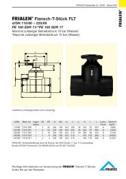
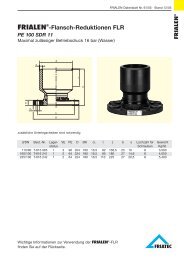
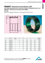
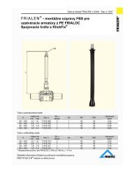
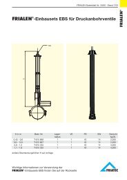
<strong>Stepped</strong> <strong>Coupling</strong>s<br />
Viking Johnson<br />
GPS<br />
Expanded Sleeve <strong>Stepped</strong> <strong>Coupling</strong><br />
<strong>Stepped</strong> <strong>Coupling</strong> with make up ring<br />
AquaGrip <strong>Stepped</strong> <strong>Coupling</strong><br />
BOLT TORQUE TABLE FOR STEPPED COUPLINGS<br />
ALL PRODUCTS EXCEPT<br />
PRODUCT<br />
AQUAGRIP<br />
AQUAGRIP<br />
COATING BLACK RILSAN BLACK RILSAN BLUE SHERAPLEX<br />
BOLT SIZE TORQUE TORQUE TORQUE<br />
lbf.ft Nm lbf.ft Nm lbf.ft Nm<br />
M12 40 - 50 55 - 65 55-60 70-75 40-50 55-65<br />
M16 70 - 80 95 - 110 - - - -<br />
14<br />
FULL BOLT TORQUE MUST BE ACHIEVED TO ENSURE THAT COUPLING / FLANGE ADAPTOR etc.<br />
FUNCTIONS TO ITS DESIGNED PERFORMANCE STANDARDS.<br />
© Viking Johnson 1999 Tel: +44 (0)1462 443322 Fax: +44 (0)1462 443311<br />
e-mail: info@vikingjohnson.co.uk
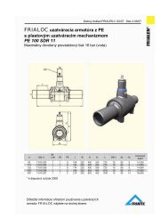
MaxiStep <strong>Coupling</strong>s<br />
Viking Johnson<br />
GPS<br />
Small End <strong>Large</strong> End Bolts Overall Dimensions Setting Weight<br />
Min Max Gasket Min Max Gasket No. - Dia x Length A A1 B C Gap (kg)<br />
(x)<br />
47.9 59.5 1637 72.2 85.0 1614 4 - M12 x 215 150 177 165 223 20 3.6<br />
59.5 72.0 1613 72.2 85.0 1614 4 - M12 x 195 164 177 165 203 20 4.3<br />
59.5 72.0 1613 88.1 102.4 1615 4 - M12 x 195 164 198 165 203 20 4.5<br />
88.1 102.4 1615 95.8 108.8 1674 4 - M12 x 195 198 201 165 203 20 4.6<br />
88.1 102.4 1615 107.2 115.1 1620 4 - M12 x 195 198 225 165 203 20 5.9<br />
88.1 102.4 1615 109.6 127.8 1759 4 - M12 x 195 198 212 165 203 20 5.4<br />
95.8 108.8 1674 107.2 115.1 1620 4 - M12 x 195 202 225 165 203 20 5.3<br />
95.8 108.8 1674 109.6 127.8 1759 4 - M12 x 195 202 212 165 203 20 5.4<br />
107.2 115.1 1620 109.6 127.8 1759 4 - M12 x 175 223 212 140 178 20 4.4<br />
107.2 115.1 1620 118.0 131.5 1616 4 - M12 x 175 223 226 140 178 20 4.5<br />
109.6 127.8 1759 118.0 131.5 1616 4 - M12 x 175 223 226 140 178 20 4.2<br />
109.6 127.8 1759 132.2 146.0 1635 4 - M12 x 215 223 250 180 223 20 6.7<br />
109.6 127.8 1759 138.9 153.2 1633 4 - M12 x 215 223 250 180 223 20 6.7<br />
132.2 146.0 1635 138.9 153.2 1633 4 - M12 x 175 250 250 140 178 20 7.4<br />
132.2 146.0 1635 158.2 169.9 1621 4 - M12 x 195 250 280 165 203 20 10.4<br />
132.2 146.0 1635 159.2 181.6 1760 4 - M12 x 215 250 274 180 223 20 10.6<br />
138.9 153.2 1633 158.2 169.9 1621 4 - M12 x 195 198 280 165 203 20 7.7<br />
138.9 153.2 1633 159.2 181.6 1760 4 - M12 x 215 250 274 180 223 20 7.8<br />
158.2 169.9 1621 159.2 181.6 1760 4 - M12 x 195 280 274 165 203 20 6.6<br />
159.2 181.6 1760 171.5 193.0 6006 4 - M12 x 215 274 285 180 223 20 8.3<br />
192.9 209.0 1758 218.1 235.0 1757 4 - M12 x 255 321 347 230 268 20 10.1<br />
192.9 209.0 1653 218.1 235.0 1654 5 - M12 x 255 321 347 230 268 20 15.3<br />
218.0 235.0 1654 230.0 247.0 1756 5 - M12 x 255 345 357 230 268 20 16.4<br />
230.0 247.0 1756 250.0 267.0 1655 6 - M12 x 255 357 279 230 268 20 17.4<br />
250.0 267.0 1655 272.0 289.0 1656 6 - M12 x 255 379 401 230 268 20 18.5<br />
272.0 289.0 1656 291.0 308.0 6007 6 - M12 x 255 399 418 230 268 20 19.5<br />
315.0 332.0 1738 322.9 339.4 1657 8 - M12 x 255 444 452 230 268 25 21.9<br />
315.0 332.0 1738 332.0 349.0 1658 8 - M12 x 255 444 461 230 268 25 22.3<br />
322.9 339.4 1657 332.0 349.0 1658 8 - M12 x 255 452 461 225 268 25 22.0<br />
322.9 339.4 1657 348.5 365.5 6008 8 - M12 x 255 450 476 225 268 25 23.0<br />
374.5 391.5 1659 394.3 411.3 1766 8 - M12 x 340 502 522 300 348 25 34.5<br />
394.3 411.3 1766 418.2 435.2 1784 10 - M12 x 340 522 545 300 348 25 36.5<br />
404.8 421.8 1767 425.0 442.0 1662 10 - M12 x 340 532 552 300 348 25 37.5<br />
425.0 442.0 1662 434.5 451.4 1768 10 - M12 x 340 552 562 300 348 25 38.9<br />
425.0 442.0 1662 447.2 464.2 1769 10 - M12 x 340 552 574 300 348 25 39.1<br />
425.0 442.0 1662 455.0 472.0 6003 10 - M12 x 340 552 582 300 348 25 39.5<br />
476.0 493.0 1770 487.3 504.3 1771 10 - M12 x 340 603 615 300 348 25 42.7<br />
476.0 493.0 1770 501.9 518.9 1772 10 - M12 x 340 603 629 300 348 25 43.0<br />
476.0 493.0 1770 510.0 527.0 6004 10 - M12 x 340 603 637 300 348 25 43.6<br />
527.0 544.0 1773 540.1 557.1 1774 12 - M12 x 340 654 667 300 348 25 47.4<br />
527.0 544.0 1773 555.3 572.3 1775 12 - M12 x 340 657 683 300 348 25 47.6<br />
527.0 544.0 1773 566.5 583.5 1776 12 - M12 x 340 657 694 300 348 25 47.8<br />
527.0 544.0 1773 582.2 599.2 1777 12 - M12 x 340 657 709 300 348 25 48.0<br />
630.0 647.0 1778 645.2 662.2 1779 14 - M12 x 340 757 772 300 348 25 55.8<br />
630.0 647.0 1778 662.0 679.0 1780 14 - M12 x 340 757 789 300 348 25 56.1<br />
630.0 647.0 1778 675.0 692.0 6005 14 - M12 x 340 757 802 300 348 25 57.0<br />
Viking Johnson can manufacture <strong>Coupling</strong> products to virtually any diameter. Those shown are for information. For sizes or diameters not shown, please request further information.<br />
15<br />
© Viking Johnson 1999 Tel: +44 (0)1462 443322 Fax: +44 (0)1462 443311<br />
e-mail: info@vikingjohnson.co.uk
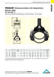
AquaGrip Transitional <strong>Coupling</strong><br />
Viking Johnson<br />
GPS<br />
PE End<br />
MaxiFit End<br />
Pipe SDR No. of Gripper Gasket Through Stud <strong>Diameter</strong> Stud Dimensions Setting Gap Weight<br />
O.D. Rating Segments Bolts Bolts Type Range Gasket Bolts A A1 B C (x) (kg)<br />
(mm) Full Half No.- Dia x Length No.- Dia x Length Min Max No.- Dia x Length Min Max<br />
63 11 10 1 6001 2 - M12 x 210 - 1 59.5 72.0 1613 - 144.0 167.5 165 210 20 40 2.8<br />
90 11 14 - 1785 4 - M12 x 210 - 1 88.1 102.4 1615 - 167.5 197.5 168 210 20 40 3.6<br />
90 17 / 17.6 14 - 1785 4 - M12 x 210 - 1 88.1 102.4 1615 - 167.5 197.5 168 210 20 40 3.7<br />
110 11 17 - 1786 4 - M12 x 210 - 1 109.6 127.8 1759 - 188.0 219.5 163 210 20 40 5.0<br />
110 17 / 17.6 17 - 1786 4 - M12 x 210 - 1 109.6 127.8 1759 - 188.0 219.5 163 210 20 40 5.0<br />
125 11 19 - 1787 4 - M12 x 210 - 2 109.6 127.8 1759 - 203.0 219.5 163 210 20 40 4.3<br />
125 17 / 17.6 19 - 1787 4 - M12 x 210 - 2 109.6 127.8 1759 - 203.0 219.5 163 210 20 40 4.4<br />
160 11 24 - 1788 - 8 - M12 x 125 3 159.2 181.6 1760 4 - M12 x 125 240.0 282.0 202 240 20 40 15.1<br />
160 17 / 17.6 24 - 1788 - 8 - M12 x 125 3 159.2 181.6 1760 4 - M12 x 145 240.0 282.0 202 240 20 40 15.2<br />
160 26 24 - 1788 - 8 - M12 x 125 3 159.2 181.6 1760 4 - M12 x 145 240.0 282.0 202 240 20 40 15.3<br />
180 11 26 - 1789 - 8 - M12 x 125 3 159.2 181.6 1760 4 - M12 x 125 257.5 282.0 186 208 20 40 16.2<br />
180 17 / 17.6 26 - 1789 - 8 - M12 x 125 3 159.2 181.6 1760 4 - M12 x 115 257.5 282.0 186 208 20 40 16.2<br />
<strong>Large</strong> <strong>Diameter</strong> <strong>Stepped</strong> <strong>Coupling</strong> -<br />
Metric Ductile Iron to Cast Iron<br />
Pipe Pipe Pipe Gasket Tolerance Pipe Pipe Pipe Gasket Tolerance Bolts Dimensions Setting Weight<br />
Type Nominal O.D. (for Type Nominal O.D. (for No.- Dia A A1 B C Gap (kg)<br />
distance L) distance L) x Length (x)<br />
Ductile Iron DN350/14" 378 J52LS +2.7,-3.5 (125) Cast Iron Cl AB DN350/14" 387 J52LS ± 2.0 (125) 8 - M12x235 465.5 474.5 184 243 25 21.3<br />
Ductile Iron DN350/14" 378 J52LS +2.7,-3.5 (125) Cast Iron Cl CD DN350/14" 399 J53LS ± 2.0 (125) 8 - M12x235 465.5 487.0 184 243 25 21.5<br />
Cast Iron Cl AB DN375/15" 413 J53LS ± 2.0 (125) Ductile Iron DN400/16" 429 J54LS +2.9,-4.0 (125) 8 - M12x235 501.5 516.5 184 243 25 23.1<br />
Cast Iron Cl CD DN375/15" 426 J54LS ± 2.0 (125) Ductile Iron DN400/16" 429 J54LS +2.9,-4.0 (125) 8 - M12x235 513.0 516.5 184 243 25 23.5<br />
Ductile Iron DN400/16" 429 J54LS +2.9,-4.0 (125) Cast Iron Cl AB DN400/16" 439 J55LS ± 2.0 (125) 8 - M12x235 516.5 528.5 184 243 25 23.8<br />
Ductile Iron DN400/16" 429 J54LS +2.9,-4.0 (125) Cast Iron Cl CD DN400/16" 453 J55LS ± 2.0 (125) 8 - M12x235 516.5 541.0 184 243 25 24.0<br />
Ductile Iron DN450/18" 480 J56LS +2.8,-4.0 (125) Cast Iron Cl AB DN450/18" 492 J57LS ± 2.0 (125) 8 - M12x235 568.0 581.0 184 243 25 26.4<br />
Ductile Iron DN450/18" 480 J56LS +2.8,-4.0 (125) Cast Iron Cl CD DN450/18" 507 J57LS ± 2.0 (125) 8 - M12x235 568.0 594.0 184 243 25 26.9<br />
Ductile Iron DN500/20" 532 J58LS +3.0,-4.0 (125) Cast Iron Cl AB DN500/20" 545 J58LS ± 2.0 (125) 10 - M12x235 620.5 633.5 184 243 25 29.3<br />
Ductile Iron DN500/20" 532 J58LS +3.0,-4.0 (125) Cast Iron Cl CD DN500/20" 560 J59LS ± 2.0 (125) 10 - M12x235 620.5 649.0 184 243 25 29.5<br />
Cast Iron Cl CD DN550/22" 613 J60LS ± 2.0 (125) Ductile Iron DN600/24" 635 J61LS +3.2,-4.5 (125) 10 - M12x235 700.0 723.0 184 243 25 33.3<br />
Ductile Iron DN600/24" 635 J61LS +3.2,-4.5 (125) Cast Iron Cl AB DN600/24" 650 J61LS ± 2.0 (125) 12 - M12x235 723.0 738.0 184 243 25 34.7<br />
Ductile Iron DN600/24" 635 J61LS +3.2,-4.5 (125) Cast Iron Cl CD DN600/24" 667 J62LS ± 2.0 (125) 12 - M12x235 723.0 754.0 184 243 25 34.9<br />
Cast Iron Cl AB DN675/27" 729 J63LS ± 2.0 (125) Ductile Iron DN700/28" 738 J63LS +3.4,-4.5 (125) 12 - M12x235 817.5 826.5 184 243 25 39.3<br />
Ductile Iron DN700/28" 738 J63LS +3.4,-4.5 (125) Cast Iron Cl CD DN675/27" 747 J63LS ± 2.0 (125) 12 - M12x235 826.5 833.5 184 243 25 39.7<br />
Ductile Iron DN700/28" 738 J63LS +3.4,-4.5 (125) Cast Iron Cl AB DN700/28" 755 J64LS ± 2.0 (125) 12 - M12x235 826.5 843.0 184 243 25 39.8<br />
Ductile Iron DN700/28" 738 J63LS +3.4,-4.5 (125) Cast Iron Cl CD DN700/28" 773* J64LS ± 2.0 (125) 12 - M12x330 826.5 860.0 284 341 25 53.6<br />
Cast Iron Cl AB DN750/30" 807 J65LS ± 2.0 (125) Ductile Iron DN800/32" 842 J65LS +1.0,-4.5 (125) 14 - M12x235 894.0 928.0 184 243 25 45.0<br />
Cast Iron Cl CD DN750/30” 826 J65LS ± 2.0 (125) Ductile Iron DN800/32" 842 J65LS +1.0,-4.5 (125) 14 - M12x235 914.0 928.0 184 243 25 44.4<br />
Ductile Iron DN800/32" 842 J65LS +1.0,-4.5 (125) Cast Iron Cl AB DN800/32" 860 J66LS ± 2.0 (125) 14 - M12x235 928.0 947.5 184 243 25 45.2<br />
Ductile Iron DN800/32" 842 J65LS +1.0,-4.5 (125) Cast Iron Cl CD DN800/32" 879* J66LS ± 2.0 (125) 14 - M12x335 928.0 966.5 298 346 25 60.7<br />
Ductile Iron DN900/36" 945 J70LS +1.0,-5.0 (150) Cast Iron Cl AB DN900/36" 964 J70LS ± 2.0 (150) 14 - M16x265 1054.0 1073.0 222 250 40 88.5<br />
Ductile Iron DN900/36" 945 J70LS +1.0,-5.0 (150) Cast Iron Cl CD DN900/36" 984* J70LS ± 2.0 (150) 14 - M16x335 1054.0 1095.0 298 346 40 104.7<br />
Ductile Iron DN1000/40" 1048 J71LS +1.0,-5.0 (150) Cast Iron Cl AB DN1000/40" 1068 J72LS ± 2.0 (150) 14 - M16x265 1156.0 1179.0 222 250 40 97.2<br />
Ductile Iron DN1000/40" 1048 J71LS +1.0,-5.0 (150) Cast Iron Cl CD DN1000/40" 1090* J72LS ± 2.0 (150) 14 - M16x335 1156.0 1200.0 298 346 40 115.0<br />
Cast Iron Cl AB DN1050/42" 1121 J120M ± 2.0 (150) Ductile Iron DN1100/42" 1152 J121M +1.0,-6.0 (150) 16 - M16x265 1245.0 1275.0 234 275 40 135.2<br />
Cast Iron Cl CD DN1050/42" 1143 J120M ± 2.0 (150) Ductile Iron DN1100/42" 1152 J121M +1.0,-6.0 (150) 16 - M16x265 1269.0 1275.0 234 275 40 137.0<br />
16<br />
Ductile Iron DN1200/48" 1255 J122M +1.0,-6.0 (150) Cast Iron Cl AB DN1200/48" 1276 J122M ± 2.0 (150) 18 - M16x265 1378.5 1400.5 234 275 40 150.4<br />
Ductile Iron DN1200/48" 1255 J122M +1.0,-6.0 (150) Cast Iron Cl CD “DN1200/48" 1300* J122M ± 2.0 (150) 18 - M16x335 1378.5 1426.0 310 346 40 176.6<br />
* Denotes long sleeve coupling due to size of step<br />
Viking Johnson can manufacture <strong>Coupling</strong> products to virtually any diameter. Those shown are for information. For sizes or diameters not shown, please request further information.<br />
© Viking Johnson 1999 Tel: +44 (0)1462 443322 Fax: +44 (0)1462 443311<br />
e-mail: info@vikingjohnson.co.uk
<strong>Large</strong> <strong>Diameter</strong> <strong>Stepped</strong> <strong>Coupling</strong> -<br />
Metric Ductile Iron to Metric PVC<br />
Viking Johnson<br />
GPS<br />
Pipe Pipe Pipe Gasket Tolerance Pipe Pipe Pipe Gasket Tolerance Bolts Dimensions Setting Weight<br />
Type Nominal O.D. (for distance L) Type Nominal O.D. (for distance L) No. - Dia A A1 B C Gap (kg)<br />
x Length<br />
(x)<br />
Metric PVC DN355 355 J51LS +1.1,-0.0 (125) Ductile Iron DN350/14" 378 J52LS +2.7,-3.5 (125) 8 - M12 x 235 443 465.5 184 243 25 20.4<br />
Ductile Iron DN350/14" 378 J52LS +2.7,-3.5 (125) Metric PVC DN400 400 J53LS +1.2,-0.0 (125) 8 - M12 x 235 463 490.5 184 243 25 22.6<br />
Ductile Iron DN400/16" 429 J54LS +2.9,-4.0 (125) Metric PVC DN450 450 J55LS +1.4,-0.0 (125) 8 - M12 x 235 517 537.0 184 243 25 23.9<br />
Metric PVC DN450 450 J55LS +1.4,-0.0 (125) Ductile Iron DN450/18" 480 J56LS +2.8,-4.0 (125) 8 - M12 x 235 537 568.0 184 243 25 25.0<br />
Ductile Iron DN450/18" 480 J56LS +2.8,-4.0 (125) Metric PVC DN500 500 J57LS +1.5,-0.0 (125) 8 - M12 x 235 568 587.0 184 243 25 26.4<br />
Metric PVC DN500 500 J57LS +1.5,-0.0 (125) Ductile Iron DN500/20" 532 J58LS +3.0,-4.0 (125) 10 - M12 x 235 587 620.5 184 243 25 28.0<br />
Ductile Iron DN500/20" 532 J58LS +3.0,-4.0 (125) Metric PVC DN560 560 J59LS +1.7,-0.0 (125) 10 - M12 x 235 621 649.0 184 243 25 29.5<br />
Metric PVC DN630 630 J61LS +1.9,-0.0 (125) Ductile Iron DN600/24" 635 J61LS +3.2,-4.5 (125) 10 - M12 x 235 717 723.0 184 243 25 33.9<br />
Metric PVC DN710 710 J63LS +2.2,-0.0 (125) Ductile Iron DN700/28" 738 J63LS +3.4,-4.5 (125) 12 - M12 x 235 800 826.5 184 243 25 38.6<br />
Metric PVC DN800 800 J65LS +2.4,-0.0 (125) Ductile Iron DN800/32" 842 J65LS +1.0,-4.5 (125) 14 - M12 x 235 887 928.0 184 243 25 43.5<br />
<strong>Large</strong> <strong>Diameter</strong> <strong>Stepped</strong> <strong>Coupling</strong> -<br />
AWWA Ductile Iron to Cast Iron<br />
Pipe Pipe Pipe Gasket Tolerance Pipe Pipe Pipe Gasket Tolerance Bolts Dimensions Setting Weight<br />
Type Nominal O.D. (for distance L) Type Nominal O.D. (for distance L) No. - A A1 B C Gap (kg)<br />
Dia x Length<br />
(x)<br />
AWWA C151 DN350/14" 382 J52LS +1.25,-2.0 (150) Cast Iron CD DN350/14” 398 J53LS +1.25,-2.0 (150) 8 - M12x235 469.0 499.5 184 243 25 22.7<br />
AWWA C151 DN400/16" 442 J55LS +1.25,-2.0 (150) Cast Iron CD DN400/16” 452 J55LS +1.25,-2.0 (150) 8 - M12x235 531.5 539.5 184 243 25 25.6<br />
AWWA C151 DN450/18" 495 J57LS +1.25,-2.0 (150) Cast Iron CD DN450/18” 506 J57LS +1.25,-2.0 (150) 10 - M12x235 582.5 593.0 184 243 25 28.7<br />
AWWA C151 DN500/20" 548 J58LS +1.25,-2.0 (150) Cast Iron CD DN500/20” 560 J59LS +1.25,-2.0 (150) 10 - M12x235 636.5 649.0 184 243 25 31.1<br />
AWWA C151 DN600/24" 655 J61LS +1.25,-2.0 (150) Cast Iron CD DN600/24” 669 J62LS +1.25,-2.0 (150) 12 - M12x235 742.0 755.0 184 243 25 36.7<br />
Cast Iron A DN750/30" 806 J65LS +2.0,-1.5 (150) AWWA C151 DN750/30” 813 J65LS +2.0,-1.5 (150) 14 - M12x235 893.5 901.0 184 243 25 44.7<br />
AWWA C151 DN750/30" 813 J65LS +2.0,-1.5 (150) Cast Iron C DN750/30” 823 J65LS +2.0,-1.5 (150) 14 - M12x235 900.0 911.0 184 243 25 44.8<br />
AWWA C151 DN750/30" 813 J65LS +2.0,-1.5 (150) Cast Iron D DN750/30” 832 J65LS +2.0,-1.5 (150) 14 - M12x235 900.0 919.5 184 243 25 44.9<br />
Cast Iron A DN900/36" 964 J70LS +2.0,-1.5 (150) AWWA C151 DN900/36” 973 J70LS +2.0,-1.5 (150) 14 - M16x265 1073.0 1082.0 222 250 30 89.5<br />
AWWA C151 DN900/36" 973 J70LS +2.0,-1.5 (150) Cast Iron C DN900/36” 983 J70LS +2.0,-1.5 (150) 14 - M16x265 1082.0 1093.0 222 250 30 90.4<br />
AWWA C151 DN900/36" 973 J70LS +2.0,-1.5 (150) Cast Iron D DN900/36” 995 J70LS +2.0,-1.5 (150) 14 - M16x265 1082.0 1094.5 222 250 30 91.2<br />
Cast Iron A DN1050/42" 1122 J120M +2.0,-1.5 (150) AWWA C151 DN1050/42” 1130 J120M +2.0,-1.5 (150) 16 - M16x265 1246.0 1254.5 234 275 30 134.3<br />
AWWA C151 DN1050/42" 1130 J120M +2.0,-1.5 (150) Cast Iron C DN1050/42” 1145 J120M +2.0,-1.5 (150) 16 - M16x265 1254.5 1271.0 234 275 30 136.1<br />
AWWA C151 DN1050/42" 1130 J120M +2.0,-1.5 (150) Cast Iron D DN1050/42” 1157 J121M +2.0,-1.5 (150) 16 - M16x265 1254.5 1280.0 234 275 30 136.3<br />
Cast Iron A DN1200/48" 1282 J122M +2.0,-1.5 (150) AWWA C151 DN1200/48” 1290 J122M +2.0,-1.5 (150) 16 - M16x265 1403.5 1414.0 234 275 30 152.7<br />
AWWA C151 DN1200/48" 1290 J122M +2.0,-1.5 (150) Cast Iron C DN1200/48” 1305 J124M +2.0,-1.5 (150) 18 - M16x265 1414.0 1427.5 310 346 30 178.3<br />
AWWA C151 DN1200/48" 1290 J122M +2.0,-1.5 (150) Cast Iron D DN1200/48” 1320 J124M +2.0,-1.5 (150) 18 - M16x265 1414.0 1443.5 310 346 30 180.0<br />
* Viking Johnson can manufacture <strong>Large</strong> <strong>Diameter</strong> <strong>Stepped</strong> <strong>Coupling</strong>s to join any pipe material to any other pipe<br />
material (with the exception of PE pipe). The above tables are only a small selection of the possible variety of<br />
stepped couplings that can be produced.<br />
Viking Johnson can manufacture <strong>Coupling</strong> products to virtually any diameter. Those shown are for information. For sizes or diameters not shown, please request further information.<br />
17<br />
© Viking Johnson 1999 Tel: +44 (0)1462 443322 Fax: +44 (0)1462 443311<br />
e-mail: info@vikingjohnson.co.uk
Juno<br />
Viking Johnson<br />
GPS<br />
JUNO TRANSITIONAL COUPLING STEEL x STEEL<br />
Dimensions<br />
Pipe <strong>Diameter</strong> A A B B T Weight<br />
Joins To (small end) (large end) (locking) (non locking) (kg)<br />
0.5" 0.75" 45.0 51.6 90 76 4.0 0.5<br />
0.75" 1" 51.6 58.0 90 85 4.0 0.5<br />
1" 1.5" 58.0 75.6 90 85 4.0 0.5<br />
1.25" 1.5" 68.5 75.6 90 83 4.25 0.9<br />
1" 1.25" 58.0 68.5 90 83 4.0 0.7<br />
1" 1.5" 58.0 75.6 90 83 4.0 0.8<br />
ST x ST<br />
JUNO TRANSITIONAL COUPLING PE x PE (mm)<br />
Dimensions<br />
Pipe <strong>Diameter</strong> A A B T Weight<br />
Joins To (small end) (large end) (kg)<br />
20 25 45.0 51.6 90 4.0 0.5<br />
25 32 51.6 58.0 90 4.0 0.6<br />
PE x PE<br />
JUNO TRANSITIONAL COUPLING STEEL x PE<br />
Dimensions<br />
Pipe <strong>Diameter</strong> A A B T Weight<br />
Joins To (steel end) (PE end) (kg)<br />
0.5" 20 45.0 45.0 78 4.0 0.4<br />
0.75" 20 51.6 45.0 81 4.0 0.5<br />
0.5" 25 45.0 51.6 81 4.0 0.5<br />
0.75" 25 51.6 51.6 81 4.0 0.5<br />
1" 25 58.0 51.6 90 4.0 0.6<br />
1" 32 58.0 58.0 90 4.0 0.6<br />
1.25" 32 68.5 58.0 90 4.0 0.7<br />
1.25" 40 68.5 68.5 90 4.25 0.7<br />
PE x ST<br />
1.5" 50 75.6 80.0 104 4.25 1.0<br />
2" 63 89.0 93.0 116 4.25 1.7<br />
18<br />
Viking Johnson can manufacture <strong>Coupling</strong> products to virtually any diameter. Those shown are for information. For sizes or diameters not shown, please request further information.<br />
© Viking Johnson 1999 Tel: +44 (0)1462 443322 Fax: +44 (0)1462 443311<br />
e-mail: info@vikingjohnson.co.uk
Flange Adaptors<br />
Viking Johnson<br />
GPS<br />
MaxiFit Flange Adaptor<br />
AquaGrip (DN225 - DN1400)<br />
AquaGrip (DN63 to DN180)<br />
FlexLock Flange Adaptor<br />
PRESSURE RATINGS<br />
Viking Johnson flange adaptors are supplied to suit the<br />
pressure rating of the flange, unless specifically ordered<br />
otherwise. The overall pressure rating of the assembled<br />
adaptor will be equal to that of the lower rated component,<br />
either pipe or flange. e.g. PN10 flange adaptors have a<br />
flange rated at a working pressure of 10bar (150 psi). The<br />
coupling component of the flange adaptor will invariably<br />
have a higher pressure rating than the flange.<br />
Flange Adaptor - General<br />
BOLT TORQUE TABLE<br />
ALL PRODUCTS EXCEPT<br />
PRODUCT<br />
AQUAGRIP<br />
AQUAGRIP<br />
COATING BLACK RILSAN BLACK RILSAN BLUE SHERAPLEX FLURENE<br />
BOLT SIZE TORQUE TORQUE TORQUE TORQUE<br />
lbf.ft Nm lbf.ft Nm lbf.ft Nm lbf.ft Nm<br />
M12 40 - 50 55 - 65 55-60 70-75 40-50 55-65 - -<br />
M16 70 - 80 95 - 110 - - - - 70 - 80 95 - 110<br />
M20 110 - 120 150 - 165 110 - 120 150 - 165<br />
M24 210 - 220 285 - 300 210 - 220 285 - 300<br />
M27 260 - 300 350 - 405 260 - 300 350 - 405<br />
M30 400 - 420 500 - 575 400 - 420 500 - 575<br />
M33 500 - 550 675 - 750 500 - 550 675 - 750<br />
FULL BOLT TORQUE MUST BE ACHIEVED TO ENSURE THAT COUPLING / FLANGE ADAPTOR etc.<br />
FUNCTIONS TO ITS DESIGNED PERFORMANCE STANDARDS.<br />
© Viking Johnson 1999 Tel: +44 (0)1462 443322 Fax: +44 (0)1462 443311<br />
e-mail: info@vikingjohnson.co.uk<br />
19
MaxiDaptor DN50/2" to DN600/24"<br />
Viking Johnson<br />
GPS<br />
Tolerance Flange Details Gasket Tee Bolts Dimensions Setting Weight<br />
Min Max No. - Dia x Length A A1 B C Gap (kg)<br />
(x)<br />
20<br />
59.5 72.0 50 PN10,16; 2" ANSI 150; 2" ADEF 1613 2 - M12 x 110 164.0 165 100 116 20 3.0<br />
72.2 85.0 60/65 PN10,16; 2.5" ANSI 150; 2.5" ADE 1614 2 - M12 x 110 177.0 185 100 116 20 3.5<br />
72.2 85.0 80 PN10,16" 1614 2 - M12 x 110 177.0 200 100 116 20 3.2<br />
88.1 102.4 80/100 PN10,16; 3" ANSI 150; 3"/4" ADE 1615 4 - M12 x 110 173.0 220 100 116 20 4.7<br />
93.0 107.0 80/100 PN10,16; 3" ANSI 150; 3"/4" ADE 1734 4 - M12 x 110 202.0 220 105 118 20 4.7<br />
109.6 127.8 100 PN10,16; 4" ANSI 150; 4" ADE 1759 4 - M12 x 110 198.5 229 100 116 20 4.8<br />
109.6 127.8 DIMA INTERN 1882 150 PN10 1759 4 - M12 x 110 198.5 229 100 116 20 4.8<br />
118.0 131.5 100 PN10,16; 4" ANSI 150; 4" ADE 1759 4 - M12 x 110 226.0 229 100 116 20 4.7<br />
132.2 146.0 125/150 PN10,16; 5" ADE; 6" ANSI 150; 6"E 1635 4 - M12 x 110 248.5 279 100 116 20 7.4<br />
138.9 153.2 125/150 PN10,16; 5" ADE; 6" ANSI 150; 6" E 1633 4 - M12 x 110 248.5 279 100 116 20 7.1<br />
159.2 181.6 150 PN10,16; 6" ANSI 150; 6" E 1760 4 - M12 x 120 261.0 285 106 131 20 6.2<br />
192.9 209.0 200 PN10,16 1758 4 - M12 x 110 319.0 340 100 130 20 11.6<br />
218.1 235.0 200 PN10,16 1757 4 - M12 x 110 345.0 340 100 130 20 10.7<br />
218.1 235.0 8" ANSI 150 1757 4 - M12 x 110 345.0 340 100 130 20 10.8<br />
250.0 267.0 250 PN10,16 1655 6 - M12 x 120 377.0 405 113 143 20 14.4<br />
250.0 267.0 10" ANSI 150 1655 6 - M12 x 125 377.0 406 126 138 20 16.3<br />
272.0 289.0 250 PN10,16 1656 6 - M12 x 120 399.0 405 113 143 20 14.0<br />
272.0 289.0 10" ANSI 150 1656 6 - M12 x 120 399.0 405 113 143 20 14.8<br />
322.9 339.4 12" ANSI 150 1657 6 - M12 x 120 449.5 483 113 143 20 16.5<br />
322.9 339.4 300 PN10,16 1657 6 - M12 x 120 449.5 460 113 143 20 16.1<br />
332.2 349.0 300 PN16 1658 6 - M12 x 135 459.0 460 126 143 20 17.6<br />
332.2 349.0 300 PN10 1658 6 - M12 x 125 459.0 460 105 138 20 22.4<br />
332.2 349.0 12" ANSI 150 1658 6 - M12 x 125 459.0 483 118 138 20 25.7<br />
351.0 368.0 350 PN10 6002 8 - M12 x 205 478.0 505 179 218 20 32.7<br />
351.0 368.0 350 PN16 6002 8 - M12 x 205 478.0 520 179 218 20 35.0<br />
351.0 368.0 14" ANSI 150 6002 6 - M12 x 205 478.0 533 177 218 20 37.0<br />
374.5 391.5 350 PN10 1659 8 - M12 x 205 501.5 505 179 218 20 30.9<br />
374.5 391.5 350 PN16 1659 8 - M12 x 205 501.5 520 179 218 20 32.6<br />
374.5 391.5 14" ANSI 150 1659 6 - M12 x 205 501.5 533 177 218 20 35.2<br />
386.0 403.0 14" ANSI 150 6035 6 - M12 x 290 513.0 533 261 218 140 41.4<br />
394.3 411.3 350 PN10 1766 8 - M12 x 290 521.3 505 271 303 140 37.9<br />
394.3 411.3 350 PN16 1766 8 - M12 x 290 521.3 520 271 303 140 39.8<br />
394.3 411.3 14" ANSI 150 1766 6 - M12 x 290 521.3 533 261 218 140 41.2<br />
404.8 421.8 400 PN10 1767 8 - M12 x 205 531.8 565 179 218 20 37.9<br />
404.8 421.8 400 PN16 1767 8 - M12 x 205 531.8 580 179 218 20 39.6<br />
404.8 421.8 16" ANSI 150 1767 8 - M12 x 205 531.8 597 177 218 20 43.6<br />
418.2 435.2 400 PN10 1784 8 - M12 x 205 545.2 565 177 218 20 36.7<br />
418.2 435.2 400 PN16 1784 8 - M12 x 205 545.2 580 177 218 20 38.9<br />
425.0 442.0 400 PN10 1662 8 - M12 x 205 552.0 565 179 218 20 35.5<br />
425.0 442.0 400 PN16 1662 8 - M12 x 205 552.0 580 179 218 20 37.7<br />
425.0 442.0 16" ANSI 150 1662 8 - M12 x 205 552.0 597 177 218 20 41.6<br />
434.4 451.4 400 PN16 1768 8 - M12 x 290 561.4 580 271 303 140 45.7<br />
434.4 451.4 16" ANSI 150 1768 8 - M12 x 205 561.4 597 182 303 20 41.2<br />
439.0 456.0 16" ANSI 150 6036 8 - M12 x 205 566.0 597 182 303 20 40.8<br />
447.2 464.2 400 PN16 1769 8 - M12 x 290 574.2 580 271 303 140 45.9<br />
447.2 464.2 16" ANSI 150 1769 8 - M12 x 290 574.2 597 266 303 140 48.9<br />
455.0 472.0 450 PN10 6003 10 - M12 x 205 582.0 615 184 218 20 41.1<br />
455.0 472.0 450 PN16 6003 10 - M12 x 205 582.0 640 184 218 20 45.6<br />
455.0 472.0 18" ANSI 150 6003 8 - M12 x 205 582.0 635 182 303 20 45.7<br />
476.0 493.0 450 PN10 1770 10 - M12 x 205 603.0 615 184 218 20 38.7<br />
476.0 493.0 450 PN16 1770 10 - M12 x 205 603.0 640 184 218 20 43.4<br />
487.3 504.3 450 PN16 1771 10 - M12 x 205 614.3 640 184 218 20 42.2<br />
487.3 504.3 500 PN16 1771 10 - M12 x 205 614.3 715 184 218 20 57.6<br />
487.3 504.3 18" ANSI 150 1771 8 - M12 x 290 614.3 635 266 303 140 50.9<br />
492.0 509.0 18" ANSI 150 6037 8 - M12 x 290 619.0 635 266 303 140 51.0<br />
501.9 518.9 450 PN16 1772 10 - M12 x 290 628.9 640 271 303 140 53.7<br />
501.9 518.9 500 PN16 6004 10 - M12 x 205 628.9 715 184 218 20 55.8<br />
501.9 518.9 18" ANSI 150" 1772 8 - M12 x 290 628.9 635 266 303 140 52.6<br />
510.0 527.0 450 PN10 6004 10 - M12 x 290 637.0 615 271 303 140 49.0<br />
510.0 527.0 450 PN16 6004 10 - M12 x 290 637.0 640 271 303 140 53.0<br />
510.0 527.0 18" ANSI 150 6004 8 - M12 x 290 637.0 637 266 303 140 52.2<br />
527.0 544.0 500 PN10 1773 10 - M12 x 205 654.0 670 184 218 20 42.9<br />
527.0 544.0 500 PN16 1773 10 - M12 x 205 654.0 715 184 218 20 52.5<br />
527.0 544.0 20" ANSI 150 1773 10 - M12 x 205 654.0 698 182 303 20 50.1<br />
540.1 557.1 500 PN16 1774 10 - M12 x 205 667.1 715 184 218 20 50.5<br />
540.1 557.1 20" ANSI 150 1774 10 - M12 x 290 667.1 698 266 303 140 58.2<br />
© Viking Johnson 1999 Tel: +44 (0)1462 443322 Fax: +44 (0)1462 443311<br />
e-mail: info@vikingjohnson.co.uk
MaxiDaptor DN50/2" to DN600/24"<br />
Viking Johnson<br />
GPS<br />
Tolerance Flange Details Gasket Tee Bolts Dimensions Setting Weight<br />
Min Max No. - Dia x Length A A1 B C Gap (kg)<br />
(x)<br />
546.0 563.0 20" ANSI 150 6038 10 - M12 x 290 673.0 698 266 303 140 58.3<br />
555.3 572.3 500 PN10 1775 10 - M12 x 290 682.3 684 271 303 140 54.3<br />
555.3 572.3 500 PN16 1775 10 - M12 x 290 682.3 715 271 303 140 62.0<br />
555.3 572.3 600 PN16 1775 10 - M12 x 205 682.3 840 184 218 20 64.0<br />
555.3 572.3 20" ANSI 150 1775 10 - M12 x 290 682.3 698 266 303 140 58.5<br />
565.0 582.0 20" ANSI 150 1776 10 - M12 x 290 692.0 698 266 303 140 58.7<br />
566.5 583.5 500 PN16 1776 10 - M12 x 290 693.5 715 271 303 140 62.2<br />
582.2 599.2 500 PN10 1777 10 - M12 x 290 709.2 670 271 303 140 54.2<br />
582.2 599.2 500 PN16 1777 10 - M12 x 290 709.2 715 271 303 140 62.5<br />
582.2 599.2 20" ANSI 150 1777 10 - M12 x 290 709.2 709 266 303 140 61.2<br />
630.0 647.0 600 PN10 1778 10 - M12 x 205 757.0 780 184 218 20 63.4<br />
630.0 647.0 24" ANSI 150 1778 10 - M12 x 205 757.0 813 182 303 20 61.2<br />
630.5 647.5 600 PN16 1778 10 - M12 x 205 757.5 840 184 218 20 66.1<br />
645.2 662.2 600 PN10 1779 10 - M12 x 290 772.2 780 271 303 140 63.1<br />
645.2 662.2 600 PN16 1779 10 - M12 x 205 772.2 840 184 218 20 63.7<br />
645.2 662.2 24" ANSI 150 1779 10 - M12 x 290 772.2 813 266 303 140 70.9<br />
654.0 671.0 24" ANSI 150 6039 10 - M12 x 290 781.0 813 266 303 140 71.0<br />
662.0 679.0 600 PN16 1780 10 - M12 x 205 789.0 840 184 218 20 60.9<br />
662.0 679.0 24" ANSI 150 1780 10 - M12 x 290 789.0 813 266 303 140 71.1<br />
675.0 692.0 600 PN10 6005 10 - M12 x 290 802.0 802 271 303 140 64.4<br />
675.0 692.0 600 PN16 6005 10 - M12 x 290 802.0 840 271 303 140 78.0<br />
675.0 692.0 24" ANSI 150 6005 10 - M12 x 290 802.0 813 266 303 140 71.3<br />
Note: MaxiDaptor with 140mm setting gap have a stepped sleeve and therefore do not slide completely over the pipe end<br />
AquaGrip Flange Adaptor DN225 to DN800<br />
Pipe SDR Flange Details No. of Clamp Dimensions End Load Type Weight<br />
O.D. Rating Nominal Specification Clamp Gasket Bolts A B C MDPE HPPE (kg)<br />
Bands<br />
No. - Dia x Length<br />
225 11 200 PN 16 2 S1763 4 - M16 x 130 340 192 - 1 1 14.5<br />
225 17/17.6 200 PN 16 2 1685 4 - M16 x 130 340 192 - 1 1 14.6<br />
225 26/33 200 PN 16 2 1685 4 - M16 x 130 340 192 - 1 1 14.7<br />
250 11 200 PN 16 2 1685 4 - M16 x 130 340 212 - 1 1 23.6<br />
250 11 250 PN 16 2 1685 4 - M16 x 130 405 186 - 1 1 22.6<br />
250 17/17.6 200 PN 16 2 1686 4 - M16 x 130 340 212 - 1 1 23.7<br />
250 17/17.6 250 PN 16 2 1686 4 - M16 x 130 405 186 - 1 1 22.7<br />
250 26/33 200 PN 16 2 1686 4 - M16 x 130 340 212 - 1 1 23.7<br />
250 26/33 250 PN 16 2 1686 4 - M16 x 130 405 186 - 1 1 22.7<br />
280 11 250 PN 16 2 1686 4 - M16 x 130 405 194 - 1 1 31.9<br />
280 17/17.6 250 PN 16 2 1713 4 - M16 x 130 405 194 - 1 1 22.9<br />
280 26/33 250 PN 16 2 1687 4 - M16 x 130 405 194 - 1 1 23.0<br />
315 11 250 PN 16 2 1686 4 - M20 x 120 405 295 170 1 1 39.6<br />
315 11 300 PN 10 2 1686 4 - M20 x 120 445 315 170 1 1 51.0<br />
315 11 300 PN 16 2 1686 4 - M20 x 120 460 245 170 1 1 46.0<br />
315 17/17.6 250 PN 16 2 1687 4 - M20 x 120 405 295 170 1 1 38.5<br />
315 17/17.6 300 PN 16 2 1687 4 - M20 x 120 460 245 170 1 1 44.0<br />
315 21 300 PN 16 2 1687 4 - M20 x 120 460 261 170 1 1 51.9<br />
315 26/33 250 PN 16 2 1687 4 - M20 x 120 405 295 170 1 1 42.0<br />
315 26/33 300 PN 16 2 1687 4 - M20 x 120 460 245 170 1 1 42.5<br />
355 11 300 PN 10 2 1687 6 - M20 x 120 445 355 140 1 1 55.4<br />
355 11 300 PN 16 2 1687 6 - M20 x 120 460 325 138 1 1 57.0<br />
355 11 350 PN 10 2 1687 6 - M20 x 120 505 325 138 1 1 65.0<br />
355 11 350 PN 16 2 1687 6 - M20 x 120 520 325 140 1 1 65.0<br />
355 11 400 PN 16 2 1687 6 - M20 x 120 580 325 140 1 1 75.1<br />
355 17/17.6 300 PN 10 2 1688 6 - M20 x 120 445 325 140 1 1 45.0<br />
355 17/17.6 300 PN 16 2 1688 6 - M20 x 120 460 325 140 1 1 47.0<br />
355 17/17.6 350 PN 16 2 1688 6 - M20 x 120 520 325 140 1 1 63.0<br />
355 21 300 PN 16 2 1688 6 - M20 x 120 460 325 140 1 1 40.0<br />
355 21 350 PN 16 2 1688 6 - M20 x 120 520 325 140 1 1 58.0<br />
355 26/33 300 PN 16 2 1688 6 - M20 x 120 460 325 140 1 1 52.0<br />
355 26/33 350 PN 10 2 1688 6 - M20 x 120 505 325 140 1 1 60.1<br />
355 26/33 350 PN 16 2 1688 6 - M20 x 120 520 325 140 1 1 61.0<br />
Dimension C is fixed for PN16 flanged version. For other configurations contact Viking Johnson for advice.<br />
Viking Johnson can manufacture <strong>Coupling</strong> products to virtually any diameter. Those shown are for information. For sizes or diameters not shown, please request further information.<br />
21<br />
© Viking Johnson 1999 Tel: +44 (0)1462 443322 Fax: +44 (0)1462 443311<br />
e-mail: info@vikingjohnson.co.uk
AquaGrip Flange Adaptor DN225 to DN800<br />
Viking Johnson<br />
GPS<br />
22<br />
Pipe SDR Flange Details No. of Clamp Dimensions End Load Type Weight<br />
O.D. Rating Nominal Specification Clamp Gasket Bolts A B C MDPE HPPE (kg)<br />
Bands<br />
No. - Dia x Length<br />
400 11 350 PN 16 3 1688 9 - M20 x 120 520 345 135 1 1 81.0<br />
400 11 400 PN 10 3 1688 9 - M20 x 120 565 345 135 1 1 91.1<br />
400 11 400 PN 16 3 1688 9 - M20 x 120 580 345 135 1 1 94.4<br />
400 13.6 400 PN 16 3 1689 9 - M20 x 120 580 345 135 1 1 90.3<br />
400 17/17.6 350 PN 16 3 1689 9 - M20 x 120 520 345 135 1 1 77.2<br />
400 17/17.6 400 PN 10 3 1689 9 - M20 x 120 565 345 135 1 1 86.1<br />
400 17/17.6 400 PN 16 3 1689 9 - M20 x 120 580 345 135 1 1 90.2<br />
400 21 400 PN 16 3 1689 9 - M20 x 120 580 345 135 1 1 92.3<br />
400 26/33 400 PN 10 3 1689 9 - M20 x 120 565 345 135 1 1 82.9<br />
400 26/33 400 PN 16 3 1689 9 - M20 x 120 580 345 135 1 1 87.2<br />
450 11 350 PN 16 3 1689 9 - M24 x 130 520 432 135 1 1 119.0<br />
450 11 400 PN 10 3 1689 9 - M24 x 130 565 369 135 1 1 112.0<br />
450 11 400 PN 16 3 1689 9 - M24 x 130 580 411 135 1 1 130.0<br />
450 11 450 PN 10 3 1689 9 - M24 x 130 615 369 135 1 1 135.0<br />
450 17/17.6 350 PN 16 3 1719 9 - M24 x 130 520 432 135 1 1 114.0<br />
450 17/17.6 400 PN 10 3 1719 9 - M24 x 130 565 411 135 1 1 121.0<br />
450 17/17.6 400 PN 16 3 1719 9 - M24 x 130 580 411 135 1 1 125.0<br />
450 17/17.6 450 PN 16 3 1719 9 - M24 x 130 640 411 135 1 1 176.0<br />
450 21 350 PN 16 3 1719 9 - M24 x 130 520 432 135 1 1 112.0<br />
450 21 400 PN 16 3 1719 9 - M24 x 130 580 411 135 1 1 123.0<br />
450 26/33 350 PN 16 3 1719 9 - M24 x 130 520 432 135 1 1 110.0<br />
450 26/33 400 PN 16 3 1719 9 - M24 x 130 580 411 135 1 1 122.0<br />
469 17/17.6 450 PN 16 3 1719 9 - M24 x 130 640 511 135 1 1 140.0<br />
469 21 450 PN 16 3 1719 9 - M24 x 130 640 411 135 1 1 136.0<br />
469 26/33 450 PN 16 3 1721 9 - M24 x 130 640 411 135 1 1 129.0<br />
500 11 400 PN 16 3 1719 9 - M24 x 130 580 432 155 1 2 136.0<br />
500 11 450 PN 16 3 1719 9 - M24 x 130 640 411 155 1 2 147.0<br />
500 11 500 PN 10 3 1719 9 - M24 x 130 670 432 155 1 2 163.0<br />
500 11 500 PN 16 3 1719 9 - M24 x 130 715 411 155 1 2 176.0<br />
500 17/17.6 400 PN 16 3 1721 9 - M24 x 130 580 432 155 1 1 129.0<br />
500 17/17.6 450 PN 16 3 1721 9 - M24 x 130 640 411 155 1 1 140.0<br />
500 17/17.6 500 PN 16 3 1719 9 - M24 x 130 715 411 155 1 1 133.0<br />
500 17/17.6 600 PN 16 3 1721 9 - M24 x 130 840 411 155 1 1 215.0<br />
500 21 400 PN 16 3 1721 9 - M24 x 130 580 432 155 1 1 127.0<br />
500 21 450 PN 16 3 1721 9 - M24 x 130 640 411 155 1 1 137.0<br />
500 21 500 PN 10 3 1721 9 - M24 x 130 670 411 155 1 1 149.0<br />
500 21 500 PN 16 3 1721 9 - M24 x 130 715 432 155 1 1 183.0<br />
500 26/33 400 PN 16 3 1721 9 - M24 x 130 580 432 155 1 1 125.0<br />
500 26/33 450 PN 16 3 1721 9 - M24 x 130 640 411 155 1 1 136.0<br />
500 26/33 500 PN 16 3 1721 9 - M24 x 130 715 411 155 1 1 163.0<br />
508 26/33 16” ANSI 150 3 1721 9 - M24 x 130 597 432 155 1 1 90.0<br />
508 33 20” ANSI 150 3 1721 9 - M24 x 130 698 432 155 1 1 129.0<br />
560 17/17.6 450 PN 16 4 1723 12 - M24 x 130 640 502 225 1 2 168.0<br />
560 17/17.6 500 PN 16 4 1723 12 - M24 x 130 715 432 225 1 2 191.0<br />
560 17/17.6 600 PN 16 4 1723 12 - M24 x 130 840 432 225 1 2 238.0<br />
560 21 450 PN 16 4 1723 12 - M24 x 130 640 502 225 1 1 163.0<br />
560 21 500 PN 16 4 1723 12 - M24 x 130 715 432 225 1 1 187.0<br />
560 26/33 450 PN 16 4 1723 12 - M24 x 130 640 502 225 1 1 159.0<br />
560 26/33 500 PN 10 4 1723 12 - M24 x 130 670 432 225 1 1 169.0<br />
560 26/33 500 PN 16 4 1723 12 - M24 x 130 715 432 225 1 1 178.0<br />
560 26/33 600 PN 16 4 1723 12 - M24 x 130 840 432 220 1 1 226.0<br />
610 33 24” ANSI 150 4 S1762 12 - M24 x 150 813 542 220 1 1 252.0<br />
630 17/17.6 600 PN 16 4 S1762 12 - M24 x 150 840 449 220 2 2 225.0<br />
630 26/33 600 PN 16 4 S1762 12 - M24 x 150 840 449 220 1 1 212.0<br />
710 17/17.6 600 PN 16 4 1795 12 - M27 x 150 840 536 270 1 2 219.0<br />
710 21 28” ANSI 150 4 S6029 12 - M27 x 150 927 569 270 1 1 273.0<br />
800 17/17.6 700 PN 16 5 S6028 15 - M27 x 150 910 565 335 2 2 456.0<br />
800 26 700 PN 6 5 S6026 15 - M27 x 150 860 565 335 2 2 383.0<br />
Dimension C is fixed for PN16 flanged version. For other configurations contact Viking Johnson for advice.<br />
Viking Johnson can manufacture <strong>Coupling</strong> products to virtually any diameter. Those shown are for information. For sizes or diameters not shown, please request further information.<br />
© Viking Johnson 1999 Tel: +44 (0)1462 443322 Fax: +44 (0)1462 443311<br />
e-mail: info@vikingjohnson.co.uk
AquaGrip Flange Adaptor DN63 to DN180<br />
Viking Johnson<br />
GPS<br />
Pipe SDR Flange Details Gasket No. of Tee Bolts Dimensions Setting Gap Weight<br />
O.D. Rating Nominal Specification Gripper No. - Dia x Length A A1 B C (x) (kg)<br />
Segments Full Half Min Max<br />
63 11 50 / 65 / 80 PN10, 16 6001 10 1 2 - M12 x 110 126.0 200 95 118 10 30 3.6<br />
90 11 80 PN10, 16 1785 14 - 4 - M12 x 110 167.5 200 96 118 10 30 3.8<br />
90 17/17.6 80 PN10, 16 1785 14 - 4 - M12 x 110 167.5 200 96 118 10 30 3.8<br />
110 11 100 PN10, 16 1786 17 - 4 - M12 x 110 188.0 220 96 118 10 30 4.2<br />
110 17/17.6 100 PN10, 16 1786 17 - 4 - M12 x 110 188.0 220 96 118 10 30 4.2<br />
125 11 100 PN10, 16 1787 19 - 4 - M12 x 110 203.0 220 96 118 10 30 4.3<br />
125 17/17.6 100 PN10, 16 1787 19 - 4 - M12 x 110 203.0 220 96 118 10 30 4.3<br />
160 11 150 PN10, 16 1788 24 - 8 - M12 x 110 240.0 285 99 124 10 30 8.1<br />
160 17/17.6 150 PN10, 16 1788 24 - 8 - M12 x 110 240.0 285 99 124 10 30 8.1<br />
180 11 150 PN10, 16 1789 26 - 8 - M12 x 110 257.5 285 101 124 10 30 8.3<br />
180 17/17.6 150 PN10, 16 1789 26 - 8 - M12 x 110 257.5 285 101 124 10 30 8.5<br />
FlexLock Flange Adaptors for Steel<br />
Pipe Flange Details Gasket No. of Stud Dimensions Setting Gap Weight Pressure (bar)<br />
O.D. Inserts Bolts A A1 B C T (x) (kg) Working Test<br />
No.- Dia x Length Min Max<br />
60.3 50 PN10,16; 2" ADE;<br />
2" ANSI 125/150 1375 3 2 - M12 x 110 133.5 165 75 120 25 10 30 3.2 16 24<br />
76.1 60/65 PN10,16; 3" ADE; 3.5" AD;<br />
3" ANSI 125/150 1394 3 2 - M12 x 110 151.5 185 75 120 25 10 30 3.4 16 24<br />
88.9 65 PN10,16; 80 PN6,10,16; 90 PN6;<br />
3" ADE; 3.5" AD; 3" ANSI 125/150 1382 4 4 - M12 x 110 163.0 200 75 117 22 10 30 5.3 16 24<br />
114.3 100 PN10,16; 110 PN6,10,16;<br />
4" ADE; 3.5"/4" ANSI 125/150 1367 4 4 - M12 x 115 194.0 220 75 127 25 10 30 5.6 16 24<br />
165.1 150 PN10,16; 6" E;<br />
6" ANSI 125/150 1369 7 8 - M12 x 115 252.5 285 75 127 25 10 30 9.3 16 24<br />
168.3 150 PN10,16; 6" E;<br />
6" ANSI 125/150 1369 7 8 - M12 x 115 255.5 285 75 127 25 10 30 9.4 16 24<br />
219.1 200 PN10; 8" E 1370 12 8 - M12 x 115 306.0 340 73 127 25 10 30 15.0 16 24<br />
219.1 200 PN16 1370 12 12 - M12 x 115 306.0 340 73 127 25 10 30 15.2 16 24<br />
219.1 8" ASA 150 1370 12 8 - M12 x 115 306.0 343 73 127 25 10 30 15.2 16 24<br />
273 250 PN10 1737 15 12 - M16 x 125 376.0 395 90 137 25 10 30 50.2 10 15<br />
273 250 PN16 1737 15 12 - M16 x 125 376.0 405 90 137 25 10 30 20.5 10 15<br />
FlexLock Flange Adaptors for Metric Ductile Iron<br />
Pipe Flange Details Gasket No. of Stud Dimensions Setting Gap Weight Pressure (bar)<br />
O.D. Inserts Bolts A A1 B C T (x) (kg) Working Test<br />
No.- Dia x Length Min Max<br />
77 60/65 PN10,16; 3” ADE; 2.5” 1690 3 2 - M12 x 115 162.0 185 75 127 25 10 30 3.7 16 24<br />
ANSI 125/150<br />
98 80 PN10,16; 3” ADE; 3” 1630 4 4 - M12 x 115 181.0 200 75 127 25 10 30 4.8 16 24<br />
ANSI 125/150<br />
118 100 PN10,16; 4” ADE; 3.5”/4” 1618 4 4 - M12 x 115 200.0 229 75 127 25 10 30 6.4 16 24<br />
ANSI 125/150<br />
170 150 PN10,16; 6” E; 6” ANSI 125/150 1369 7 8 - M12 x 115 257.5 285 75 127 25 10 30 9.4 16 24<br />
170 DIMA INTERN 1882 - 150 PN10 1369 7 6 - M12 x 115 257.5 285 73 127 25 10 30 11.1 10 15<br />
222 200 PN10; 8” E 1631 12 8 - M16 x 125 316.0 340 75 137 25 10 30 13.9 16 2<br />
222 200 PN16 1631 12 6 - M16 x 125 316.0 340 75 137 25 10 30 13.8 16 24<br />
274 250 PN10 1737 15 12 - M16 x 125 376.0 395 90 137 25 10 30 20.2 10 15<br />
274 250 PN16 1737 15 12 - M16 x 125 376.0 405 90 137 25 10 30 20.5 10 15<br />
Viking Johnson can manufacture <strong>Coupling</strong> products to virtually any diameter. Those shown are for information. For sizes or diameters not shown, please request further information.<br />
23<br />
© Viking Johnson 1999 Tel: +44 (0)1462 443322 Fax: +44 (0)1462 443311<br />
e-mail: info@vikingjohnson.co.uk
QuickFit Flange Adaptor<br />
Viking Johnson<br />
GPS<br />
24<br />
Pipe Pipe Pipe Flange Details Gasket Tee Dimensions Setting Weight<br />
Nominal Type O.D. Bolts A A1 B C T Gap (kg)<br />
No. - Dia x Length<br />
(x)<br />
DN40/1.5" 1.5" AC 57.0 50 PN10,16,25,40; 2" ANSI 150; 2" ADE 1599 2 - M12 x 110 138.0 165 75 118 16 20 3.0<br />
DN40/1.5" ISO 4200/2 Steel 57.0 50 PN10,16,25,40; 2" ANSI 150; 2" ADE 1599 2 - M12 x 110 138.0 165 75 118 16 20 3.0<br />
DN50/2" Steel, Imp PVC 60.3 50 PN10,16,25,40; 2" ANSI 150; 2" ADE 1500 2 - M12 x 110 138.0 165 75 118 16 20 3.0<br />
DN50 Metric PVC 63.0 50 PN10,16,25,40; 2" ANSI 150; 2" ADEF 1582 2 - M12 x 110 138.0 165 75 118 16 20 3.0<br />
DN50 AWWA cl A CI 63.5 50 PN10,16,25,40; 2" ANSI 150; 2" ADEF 1582 2 - M12 x 110 138.0 165 75 118 16 20 3.0<br />
DN50/2" Cl 25 AC 69.0 65 PN10,16; 2" ANSI 150; 2.5"ADE 1565 2 - M12 x 110 150.0 185 75 118 16 20 3.4<br />
DN50/2" Cast Iron 69.1 65 PN10,16; 2" ANSI 150; 2.5"ADE 1565 2 - M12 x 110 150.0 185 75 118 16 20 3.4<br />
DN65/2.5" ISO 4200/2 Steel 70.0 65 PN10,16; 2.5" ANSI 150; 2.5"ADE 1727 2 - M12 x 110 150.0 185 93 118 16 20 3.1<br />
DN65/2.5" ISO 4200/3 Steel 73.0 65 PN10,16; 2.5" ANSI 150; 2.5"ADE 1727 2 - M12 x 110 150.0 185 93 118 16 20 3.1<br />
DN65/2.5" API 5L 73.0 65 PN10,16; 2.5" ANSI 150; 2.5"ADE 1727 2 - M12 x 110 150.0 185 93 118 16 20 3.1<br />
DN65/2.5" Steel, Imp PVC 76.1 65 PN10,16; 2.5" ANSI 150 1560 2 - M12 x 110 150.0 185 75 118 16 20 3.3<br />
DN75 Metric PVC 75.0 65 PN10,16; 2.5" ANSI 150 1560 2 - M12 x 110 150.0 185 75 118 16 20 3.3<br />
DN80/3" Steel, Imp PVC 88.9 80 PN,10,16; 3" ANSI 150; 3" ADE 1501 4 - M12 x 110 161.0 200 75 118 16 20 4.3<br />
DN80/3" Metric PVC 90.0 80 PN,10,16; 3" ANSI 150 1501 4 - M12 x 110 161.0 200 75 118 16 20 4.7<br />
DN80/3" Cast Iron 96.0 80 PN,10,16; 3" ANSI 150; 3" ADE 1406 4 - M12 x 110 177.0 200 75 118 16 20 4.3<br />
DN80/3" AC 96.0 80 PN,10,16; 3" ANSI 150; 3" ADE 1406 4 - M12 x 110 177.0 200 75 118 16 20 4.3<br />
DN80/3" Metric Ductile Iron 98.0 80 PN,10,16; 3" ANSI 150; 4" ADE 1406 4 - M12 x 110 177.0 220 93 118 16 20 4.1<br />
DN100/4" ISO 4200/3 Steel 108.0 100 PN10,16; 4" ANSI 150; 4" AD 1596 4 - M12 x 110 183.0 229 75 118 16 20 5.5<br />
DN110 Metric PVC 110.0 100 PN10,16; 4" ANSI 150; 4" AD 1561 4 - M12 x 110 183.0 229 75 118 16 20 5.5<br />
DN100/4" Steel, Imp PVC 114.3 100 PN10,16; 4" ANSI 150; 4" AD 1404 4 - M12 x 110 194.0 229 75 118 16 20 4.9<br />
DN100/4 Metric Ductile Iron 118.0 100 PN10,16; 4" ANSI 150; 4" AD 1404 4 - M12 x 110 194.0 229 75 118 16 20 4.9<br />
DN100/4" Cast Iron 122.0 100 PN10,16; 4" ADE 1580 4 - M12 x 110 198.0 220 75 118 16 20 4.9<br />
DN100/4" AWWA Ductile Iron 122.0 100 PN10,16; 4" ADE 1580 4 - M12 x 110 198.0 220 75 118 16 20 4.9<br />
DN100/4" AWWA C209 PVC 122.0 100 PN10,16; 4" ADE 1580 4 - M12 x 110 198.0 220 75 118 16 20 4.9<br />
DN125 Metric PVC 125.0 100 PN10,16; 4" ANSI 150; 4" ADE 1580 4 - M12 x 110 198.0 254 75 118 16 20 6.9<br />
DN125/5" ISO 4200/2 Steel 133.0 125 PN10,16; 5" ADE 1563 4 - M12 x 110 214.0 254 75 118 16 20 6.9<br />
DN125/5" Steel 139.7 125 PN10,16; 5" ADE 1503 4 - M12 x 110 214.0 254 75 118 16 20 6.6<br />
DN125/5" Metric PVC 140.0 125 PN10,16; 5" ADE 1503 4 - M12 x 110 214.0 254 75 118 16 20 6.6<br />
DN125/5" Imp PVC 140.2 125 PN10,16; 5" ADE 1503 4 - M12 x 110 214.0 254 75 118 16 20 6.6<br />
DN125/5" Steel 141.3 125 PN10,16; 5" ADE 1503 4 - M12 x 110 214.0 254 75 118 16 20 6.6<br />
DN150/6" ISO 4200/3 Steel 159.0 150 PN10,16; 6" ANSI 150; 6" E 1559 4 - M12 x 110 240.0 285 75 118 16 20 8.5<br />
DN150/6" Metric PVC 160.0 150 PN10,16; 6" ANSI 150; 6" E 1559 4 - M12 x 110 240.0 285 75 118 16 20 8.5<br />
DN150/6" Steel 168.3 150 PN10,16; 6" ANSI 150; 6" E A1418 4 - M12 x 110 255.5 285 75 118 19 20 8.4<br />
DN150/6" BS DI 170.0 150 PN10,16; 6" ANSI 150; 6" E A1418 4 - M12 x 110 257.0 285 75 118 19 20 8.4<br />
DN150/6" ANSI DI/PVC 175.3 150 PN10,16; 6" ANSI 150; 6" E A1409 4 - M12 x 110 262.5 285 75 118 19 20 8.3<br />
DN150/6" BS CI 177.3 150 PN10,16; 6" ANSI 150; 6" E A1506 4 - M12 x 110 264.5 285 75 118 19 20 8.3<br />
DN150/6" ISO Steel 177.8 150 PN10,16; 6" ANSI 150; 6" E A1506 4 - M12 x 110 265.0 285 75 118 19 20 8.3<br />
DN180 Metric PVC 180.0 150 PN10,16; 6" ANSI 150 A1506 4 - M12 x 110 267.0 285 75 118 19 20 9.2<br />
DN200 Metric PVC 200.0 200 PN10; 8" ANSI 150; 8" E 736* 4 - M12 x 110 287.0 343 75 118 19 20 10.6<br />
DN200/8" Steel 219.1 200 PN10; 8" ANSI 150; 8" E A1419 4 - M12 x 110 306.0 343 75 118 19 20 11.7<br />
DN200/8" BS DI 222.0 200 PN10; 8" ANSI 150; 8" E A1419 4 - M12 x 110 309.0 343 75 118 19 20 11.7<br />
DN200/8" Steel 219.1 200 PN16 A1419 6 - M12 x 110 306.0 340 75 118 19 20 12.3<br />
DN200/8" BS DI 222.0 200 PN16 A1419 6 - M12 x 110 309.0 340 75 118 19 20 12.3<br />
DN225 Metric PVC 225.0 200 PN10; 8" ANSI 150; 8" E A1401 8 - M12 x 110 312.0 343 75 118 19 20 10.9<br />
DN225 Metric PVC 225.0 200 PN16 A1401 6 - M12 x 110 312.0 340 75 118 19 20 11.8<br />
DN200/8" ANSI DI/PVC 230.0 200 PN10; 8" ANSI 150; 8" E A1550 8 - M12 x 110 317.0 343 75 118 19 20 12.1<br />
DN200/8" BS CI 232.0 200 PN10; 8" ANSI 150; 8" E A1550 8 - M12 x 110 319.0 343 75 118 19 20 12.1<br />
DN200/8" BS CI 232.0 8” AD A1550 8 - M12 x 110 319.0 337 73 108 18 20 13.9<br />
DN200/8" BS CI 232.0 200 PN16 A1550 6 - M12 x 110 319.0 340 75 118 19 20 11.5<br />
DN225/9” Steel/PVC 244.5 200 PN16 A1542 6 - M12 x 100 331.5 340 73 108 18 20 13.3<br />
DN250 Metric PVC 250.0 250 PN16 A1402 6 - M12 x 120 337.0 405 90 128 22 20 17.2<br />
DN250 Metric PVC 250.0 250 PN10; 10" E A1402 6 - M12 x 120 337.0 406 90 128 19 20 16.3<br />
DN225/9" CI 259.0 9" AD A1551 8 - M12 x 120 346.0 368 90 128 19 20 16.0<br />
DN225/9" CI 259.0 225 PN10 A1551 8 - M12 x 120 346.0 370 90 128 19 20 16.0<br />
DN225/9" CI 259.0 225 PN16; 9" E A1551 6 - M12 x 120 346.0 370 90 128 19 20 15.3<br />
Viking Johnson can manufacture <strong>Coupling</strong> products to virtually any diameter. Those shown are for information. For sizes or diameters not shown, please request further information.<br />
© Viking Johnson 1999 Tel: +44 (0)1462 443322 Fax: +44 (0)1462 443311<br />
e-mail: info@vikingjohnson.co.uk
QuickFit Flange Adaptor<br />
Viking Johnson<br />
GPS<br />
Pipe Pipe Pipe Flange Details Gasket Tee Bolts Dimensions Setting Weight<br />
Nominal Type O.D. No. A A1 B C T Gap (kg)<br />
- Dia x Length (x)<br />
DN225/9" CI 259.0 250 PN16 A1551 6 - M12 x 120 346.0 405 90 128 22 20 17.2<br />
DN250/10" Steel 273.0 250 PN10; 10" E A1544 6 - M12 x 120 360.0 406 90 128 19 20 16.0<br />
DN250/10" DI 274.0 250 PN10; 10" E A1544 6 - M12 x 120 361.0 406 90 128 19 20 16.0<br />
DN250/10" Steel 273.0 250 PN16 A1544 6 - M12 x 120 360.0 406 90 128 22 20 17.8<br />
DN250/10" DI 274.0 250 PN16 A1544 6 - M12 x 120 361.0 406 90 128 22 20 17.8<br />
DN280 Metric PVC 280.0 250 PN16 A1411 6 - M12 x 120 367.0 432 90 128 19 20 16.3<br />
DN250/10" ANSI DI/PVC/CI 282.0 10" ANSI 150 A1411 6 - M12 x 120 369.0 406 90 128 19 20 18.5<br />
DN250/10" CI 286.0 10" AD A1553 8 - M12 x 120 373.0 406 90 128 19 20 18.5<br />
DN250/10" CI 286.0 250 PN10; 10" E A1553 6 - M12 x 120 373.0 406 90 128 19 20 16.6<br />
DN250/10" CI 286.0 250 PN16 A1553 6 - M12 x 120 373.0 405 90 128 22 20 16.3<br />
DN315 Metric PVC 315.0 300 PN10; 12" D A1403 6 - M12 x 120 402.0 457 90 128 19 20 20.9<br />
DN315 Metric PVC 315.0 300 PN16 A1403 6 - M12 x 120 402.0 460 90 128 22 20 20.6<br />
DN300/12" Steel 323.9 300 PN16 A1420 6 - M12 x 120 410.9 460 90 128 22 20 21.4<br />
DN300/12" DI 326.0 300 PN16 A1420 6 - M12 x 120 413.0 460 90 128 22 20 21.4<br />
DN300/12" BS CI cl AB 333.8 300 PN16 A1555 6 - M12 x 120 420.8 460 90 128 22 20 19.5<br />
DN300/12" ANSI DI/PVC/CI 335.3 12" ANSI 150; 12" E A1412 6 - M12 x 120 422.3 483 90 128 19 20 20.1<br />
DN300/12" ANSI DI cl D 343.0 12" ANSI 150; 12" E A1412 6 - M12 x 120 430.0 483 90 128 19 20 20.0<br />
DN300/12" BS CI cl CD 345.0 12" A A1554 8 - M12 x 120 432.0 457 90 128 19 20 20.9<br />
DN300/12" BS CI cl CD 345.0 300 PN10; 12" D A1554 6 - M12 x 120 432.0 457 90 128 19 20 20.9<br />
DN300/12" BS CI cl CD 345.0 300 PN16 A1554 6 - M12 x 120 432.0 460 90 128 22 20 18.4<br />
* denotes unfitted gasket<br />
The products previously marketed as MidiDaptor require different gaskets to those listed above. Please contact Viking Johnson Technical Department for further details.<br />
<strong>Large</strong> <strong>Diameter</strong> Flange Adaptors for PVC Pipes<br />
Pipe Pipe Flange Details Gasket Dimensions Setting Flange Holes Weight<br />
Type O.D. Nominal Specification A A1 B C T Gap No. <strong>Diameter</strong> PCD (kg)<br />
(x)<br />
Metric PVC 355.0 350 PN10 J51LS 442.0 505 91 148 18 25 16 23 460.0 22.6<br />
Metric PVC 355.0 350 PN16 J51LS 442.0 520 91 148 18 25 16 28 470.0 23.9<br />
Imp PVC 355.6 350 PN10 J51LS 442.5 505 91 148 18 25 16 23 460.0 22.6<br />
Imp PVC 355.6 350 PN16 J51LS 442.5 520 91 148 18 25 16 28 470.0 23.9<br />
Imp PVC 355.6 350 PN25 J51LS 442.5 555 98 155 25 25 16 34 490.0 34.1<br />
Imp PVC 355.6 14" TABLE DE J51LS 442.5 527 91 148 18 25 12 25 470.0 25.0<br />
Imp PVC 355.6 14" TABLE F J51LS 442.5 553 91 155 25 25 16 29 495.0 34.6<br />
IPS 355.6 14" ANSI 150 J51LS 442.5 533 91 155 25 25 12 29 476.0 31.6<br />
AWWA C900 388.0 14" ANSI 150 J52LS 475.0 533 91 153 18 25 12 29 476.0 28.1<br />
Metric PVC 400.0 400 PN10 J53LS 487.0 565 91 155 25 25 16 28 515.0 32.6<br />
Metric PVC 400.0 400 PN16 J53LS 487.0 580 91 155 25 25 16 31 525.0 34.8<br />
Imp PVC 406.4 400 PN10 J53LS 493.5 565 91 148 18 25 16 28 515.0 26.1<br />
Imp PVC 406.4 400 PN16 J53LS 493.5 580 91 148 18 25 16 31 525.0 27.7<br />
Imp PVC 406.4 400 PN25 J53LS 493.5 620 98 155 25 25 16 37 550.0 40.5<br />
Imp PVC 406.4 16" TABLE ADE J53LS 493.5 578 91 148 18 25 12 25 520.5 34.8<br />
IPS 406.4 16" ANSI 150 J53LS 493.5 597 91 155 25 25 16 29 540.0 37.5<br />
AWWA C900 442.0 16" ANSI 150 J55LS 529.0 597 91 155 25 25 16 29 540.0 33.6<br />
Metric PVC 450.0 450 PN10 J55LS 537.0 615 96 153 23 25 20 28 565.0 33.3<br />
Metric PVC 450.0 450 PN16 J55LS 537.0 640 96 153 23 25 20 31 585.0 39.0<br />
Imp PVC 457.0 450 PN10 J55LS 544.0 615 96 153 23 25 20 28 565.0 35.2<br />
Imp PVC 457.0 450 PN16 J55LS 544.0 640 96 153 23 25 20 31 585.0 37.2<br />
Imp PVC 457.0 450 PN25 J55LS 544.0 670 98 155 25 25 20 37 670.0 44.1<br />
Imp PVC 457.0 18" TABLE AD J55LS 544.0 641 96 153 23 25 12 25 584.0 38.6<br />
Imp PVC 457.0 18" TABLE E J55LS 544.0 641 96 153 23 25 16 25 584.0 38.5<br />
IPS 457.0 16" ANSI 150 J55LS 544.0 597 96 155 25 25 16 29 540.0 31.9<br />
AWWA C900 495.0 18" ANSI 150 J57LS 582.0 635 96 155 25 25 16 32 578.0 38.6<br />
Viking Johnson can manufacture <strong>Coupling</strong> products to virtually any diameter. Those shown are for information. For sizes or diameters not shown, please request further information.<br />
25<br />
© Viking Johnson 1999 Tel: +44 (0)1462 443322 Fax: +44 (0)1462 443311<br />
e-mail: info@vikingjohnson.co.uk
<strong>Large</strong> <strong>Diameter</strong> Flange Adaptors for PVC Pipe<br />
Viking Johnson<br />
GPS<br />
Pipe Pipe Flange Details Dimensions Setting Flange Holes Weight<br />
Type O.D. Nominal Specification Gasket A A1 B C T Gap No. <strong>Diameter</strong> PCD (kg)<br />
(x)<br />
Metric PVC 500 500 PN10 J57LS 587 670 96 155 25 25 20 28 620.0 40.8<br />
Metric PVC 500 500 PN16 J57LS 587 715 96 155 25 25 20 34 650.0 49.0<br />
Imp PVC 508 500 PN10 J57LS 595 670 96 153 23 25 20 28 620.0 37.5<br />
Imp PVC 508 500 PN16 J57LS 595 715 96 153 23 25 20 34 650.0 45.2<br />
Imp PVC 508 500 PN25 J57LS 595 730 98 155 25 25 20 37 660.0 50.6<br />
Imp PVC 508 20” TABLE DE J57LS 595 705 96 153 23 25 16 25 641.5 44.9<br />
IPS 508 20” ANSI 150 J57LS 595 698 96 155 25 25 20 32 635.0 44.7<br />
AWWA C900 549 20” ANSI 150 J69LS 636 698 96 155 25 25 20 32 635.0 38.9<br />
Imp PVC 559 500 PN16 J59LS 646 715 96 155 25 25 20 34 650.0 38.7<br />
Imp PVC 559 550 PN16 J59LS 646 775 96 153 23 25 20 34 710.0 51.3<br />
Imp PVC 559 21" TABLE E J59LS 646 737 96 153 23 25 16 29 673.0 44.4<br />
Imp PVC 559 22" TABLE DE J59LS 646 762 96 153 23 25 16 29 698.5 49.6<br />
Metric PVC 560 500 PN16 J59LS 647 715 96 153 23 25 20 34 650.0 38.3<br />
Metric PVC 560 550 PN16 J59LS 647 775 96 153 23 25 20 34 710.0 50.9<br />
Imp PVC 610 600 PN10 J60LS 697 780 96 153 23 25 20 31 725.0 45.7<br />
Imp PVC 610 600 PN16 J60LS 697 840 96 153 23 25 20 37 770.0 58.2<br />
Imp PVC 610 600 PN25 J60LS 697 845 98 155 25 25 20 40 770.0 62.4<br />
Imp PVC 610 24" TABLE A J60LS 697 826 96 153 23 25 12 29 755.5 57.6<br />
Imp PVC 610 24" TABLE D J60LS 697 826 96 153 23 25 16 29 755.5 56.7<br />
Imp PVC 610 24" TABLE E J60LS 697 826 96 153 23 25 16 32 756.0 56.3<br />
Imp PVC 610 24" TABLE F J60LS 697 851 96 155 25 25 24 35 781.0 64.6<br />
IPS 610 24" ANSI 150 J60LS 697 813 96 155 25 25 20 35 750.0 55.5<br />
Metric PVC 630 600 PN10 J61LS 717 780 96 153 23 25 20 31 725.0 42.3<br />
Metric PVC 630 600 PN16 J61LS 717 840 96 153 23 25 20 37 770.0 54.8<br />
AWWA C900 655 24" ANSI 150 J61LS 742 813 96 155 25 25 20 35 749.5 51.1<br />
Metric PVC 710 700 PN10 J63LS 797 895 96 153 23 25 24 31 840.0 55.8<br />
Metric PVC 710 700 PN16 J63LS 797 910 96 153 23 25 24 37 840.0 58.5<br />
Imp PVC 711 700 PN10 J63LS 798 895 96 153 23 25 24 31 840.0 55.8<br />
Imp PVC 711 700 PN16 J63LS 798 910 96 153 23 25 24 37 840.0 58.3<br />
Imp PVC 711 700 PN25 J63LS 798 960 98 155 25 25 24 43 875.0 74.2<br />
Imp PVC 711 27" TABLE D J63LS 798 908 96 153 23 25 20 29 844.5 59.8<br />
Imp PVC 711 27" TABLE E J63LS 798 908 96 153 23 25 20 32 844.5 59.3<br />
Imp PVC 711 28" ANSI150 J63LS 798 927 96 155 25 25 28 35 863.5 66.4<br />
Metric PVC 800 800 PN10 J64LS 887 1015 96 153 23 25 24 34 950.0 69.7<br />
Metric PVC 800 800 PN16 J64LS 887 1025 96 153 23 25 24 40 950.0 71.8<br />
Imp PVC 813 800 PN10 J65LS 900 1015 96 153 23 25 24 34 950.0 67.9<br />
Imp PVC 813 800 PN16 J65LS 900 1025 96 153 23 25 24 40 950.0 69.3<br />
Imp PVC 813 30" TABLE E J65LS 900 997 98 153 25 25 20 35 927.0 63.0<br />
Imp PVC 813 33" TABLE DE J65LS 900 1092 98 155 25 25 20 35 1016.0 97.5<br />
IPS 813 32" ANSI150 J65LS 900 1060 98 155 25 25 28 41 978.0 99.6<br />
AWWA C900 813 32" ANSI 150 J65LS 900 1060 98 155 25 25 28 41 978.0 99.6<br />
Metric PVC 900 900 PN10 J67LS 987 1115 98 153 25 25 28 34 1050.0 79.4<br />
Metric PVC 900 900 PN16 J67LS 987 1125 98 153 25 25 28 40 1050.0 80.9<br />
Imp PVC 914 900 PN10 J67LS 1001 1115 98 153 25 25 28 34 1050.0 79.4<br />
Imp PVC 914 900 PN16 J67LS 1001 1125 98 153 25 25 28 40 1050.0 80.9<br />
Imp PVC 914 36" TABLE DE J67LS 1001 1175 98 153 25 25 24 35 1092.0 101.0<br />
IPS 914 36" ANSI 125 J70LS 1001 1168 112 169 25 25 32 41 1086.0 105.0<br />
26<br />
AWWA C900 973 36" ANSI 125 J70LS 1082 1168 112 169 25 30 32 41 1086.0 105.0<br />
AWWA C900 973 38" ANSI 150 J70LS 1082 1238 112 169 25 30 32 41 1150.0 126.0<br />
Met PVC 1000 1000 PN10 J71LS 1109 1230 112 169 25 30 28 37 1160.0 112.0<br />
Viking Johnson can manufacture <strong>Coupling</strong> products to virtually any diameter. Those shown are for information. For sizes or diameters not shown, please request further information.<br />
© Viking Johnson 1999 Tel: +44 (0)1462 443322 Fax: +44 (0)1462 443311<br />
e-mail: info@vikingjohnson.co.uk
<strong>Large</strong> <strong>Diameter</strong> Flange Adaptors for PVC Pipe<br />
Viking Johnson<br />
GPS<br />
Pipe Pipe Flange Details Dimensions Setting Flange Holes Weight<br />
Type O.D. Nominal Specification Gasket A A1 B C T Gap No. <strong>Diameter</strong> PCD (kg)<br />
(x)<br />
Met PVC 1000 1000 PN16 J71LS 1109 1255 112 169 25 30 28 43 1170.0 123.0<br />
Imp PVC 1016 1000 PN10 J71LS 1125 1230 112 169 25 30 28 37 1160.0 112.0<br />
Imp PVC 1016 1000 PN16 J71LS 1125 1255 112 169 25 30 28 43 1170.0 119.0<br />
Imp PVC 1016 39" TABLE D J71LS 1125 1257 112 169 25 30 24 35 1175.0 123.0<br />
Imp PVC 1118 1100 PN10 J73LS 1227 1340 112 169 25 30 32 37 1270.0 125.0<br />
Imp PVC 1118 42" TABLE E J73LS 1227 1334 112 169 25 30 28 38 1251.0 123.0<br />
Metric PVC 1200 1200 PN10 J121M 1325 1455 125 182 38 30 32 40 1380.0 201.0<br />
Metric PVC 1200 1200 PN16 J121M 1325 1485 125 182 38 30 32 49 1390.0 226.0<br />
Imp PVC 1220 1200 PN10 J121M 1345 1455 125 182 38 30 32 40 1380.0 201.0<br />
Imp PVC 1220 1200 PN16 J121M 1345 1485 125 182 38 30 32 49 1390.0 216.0<br />
Imp PVC 1220 1200 PN25 J121M 1345 1530 125 182 38 30 32 56 1420.0 242.0<br />
Imp PVC 1220 48" TABLE A J121M 1345 1416 125 182 38 30 28 29 1352.5 182.0<br />
Imp PVC 1220 48" TABLE D J121M 1345 1492 125 182 38 30 32 35 1409.5 229.0<br />
Imp PVC 1220 48" TABLE E J121M 1345 1492 125 182 38 30 32 38 1409.5 228.0<br />
Metric PVC 1400 1400 PN10 J125M 1525 1675 125 182 38 30 36 43 1590.0 245.0<br />
Metric PVC 1400 1400 PN16 J125M 1525 1685 125 182 38 30 36 49 1590.0 248.0<br />
Imp PVC 1420 1400 PN10 J125M 1545 1675 125 182 38 30 36 43 1590.0 245.0<br />
Imp PVC 1420 1400 PN16 J125M 1545 1685 125 182 38 30 36 49 1590.0 248.0<br />
Imp PVC 1420 54" TABLE D J125M 1545 1607 125 182 38 30 36 35 1530.5 199.0<br />
Metric PVC 1600 1600 PN10 J127M 1725 1915 125 182 38 30 40 49 1820.0 293.0<br />
Metric PVC 1600 1600 PN16 J127M 1725 1930 125 182 38 30 40 56 1820.0 299.0<br />
Imp PVC 1620 1600 PN10 J127M 1745 1915 125 182 38 30 40 49 1820.0 308.0<br />
Imp PVC 1620 1600 PN16 J127M 1745 1930 125 182 38 30 40 56 1820.0 314.0<br />
Imp PVC 1620 66" TABLE D J127M 1745 1943 125 182 38 30 40 38 1860.5 342.0<br />
Metric PVC 1800 1800 PN10 J130M 1925 2115 125 182 38 30 44 49 2020.0 322.0<br />
Metric PVC 1800 1800 PN16 J130M 1925 2130 125 182 38 30 44 56 2020.0 340.0<br />
Imp PVC 1820 1800 PN10 J130M 1945 2115 125 182 38 30 44 49 2020.0 337.0<br />
Imp PVC 1820 1800 PN16 J130M 1945 2130 125 182 38 30 44 56 2020.0 343.0<br />
Metric PVC 2000 2000 PN10 J186H 2135 2325 185 274 60 30 48 49 2230.0 668.0<br />
Metric PVC 2000 2000 PN16 J186H 2135 2345 185 274 60 30 48 62 2230.0 650.0<br />
<strong>Large</strong> <strong>Diameter</strong> Flange Adaptors for Cast Iron Pipe<br />
Pipe Pipe Flange Details Dimensions Setting Flange Holes Weight<br />
Type O.D. Nominal Specification Gasket A A1 B C T Gap No. Dia. PCD (kg)<br />
(x)<br />
AWWA CI Cl AB 382 14" ANSI 150 J52LS 469 533 98 155 18 25 12 29 476.0 29.3<br />
BS1211 Cl AB 387 350 PN 6 J52LS 474 520 98 155 18 25 16 28 470.0 26.4<br />
BS1211 Cl AB 387 400 PN 16 J52LS 474 580 98 155 18 25 16 31 525.0 36.0<br />
BS1211 Cl AB 387 14" TABLE DE J52LS 474 527 98 148 18 25 12 25 470.0 23.1<br />
AWWA CI Cl CD 397 14" ANSI 150 J53LS 484 533 98 155 18 25 12 29 476.0 27.4<br />
BS 78 Cl CD 399 350 PN 16 J53LS 486 520 98 148 18 25 16 28 470.0 21.2<br />
BS 78 Cl CD 399 400 PN 10 J53LS 486 565 98 155 18 25 16 28 515.0 32.6<br />
BS 78 Cl CD 399 400 PN 16 J53LS 486 580 98 155 18 25 16 31 525.0 34.8<br />
BS 78 Cl CD 399 14" TABLE DE J53LS 486 527 98 148 18 25 12 25 470.0 22.3<br />
BS1211 Cl AB 413 400 PN 10 J53LS 500 565 98 155 18 25 16 28 515.0 31.1<br />
BS1211 Cl AB 413 400 PN 16 J53LS 500 580 98 155 18 25 16 31 525.0 33.3<br />
BS1211 Cl AB 413 16" TABLE ADE J53LS 500 578 98 155 18 25 12 25 520.5 34.0<br />
BS 78 Cl CD 426 400 PN 10 J54LS 513 565 98 148 18 25 16 28 515.0 24.5<br />
BS 78 Cl CD 426 400 PN 16 J54LS 513 580 98 148 18 25 16 31 525.0 26.1<br />
BS 78 Cl CD 426 16" TABLE ADE J54LS 513 578 98 148 18 25 12 25 520.5 26.5<br />
Viking Johnson can manufacture <strong>Coupling</strong> products to virtually any diameter. Those shown are for information. For sizes or diameters not shown, please request further information.<br />
27<br />
© Viking Johnson 1999 Tel: +44 (0)1462 443322 Fax: +44 (0)1462 443311<br />
e-mail: info@vikingjohnson.co.uk
<strong>Large</strong> <strong>Diameter</strong> Flange Adaptors for Cast Iron Pipe<br />
Viking Johnson<br />
GPS<br />
Pipe Pipe Flange Details Dimensions Setting Gap Flange Holes Weight<br />
Type O.D. Nominal Specification Gasket A A1 B C T (x) No. Dia. PCD (kg)<br />
BS1211 Cl AB 439 400 PN 10 J55LS 526 565 98 148 18 25 16 28 515.0 23.7<br />
BS1211 Cl AB 439 400 PN 16 J55LS 526 580 98 148 18 25 16 31 525.0 25.2<br />
BS1211 Cl AB 439 16" TABLE ADE J55LS 526 578 98 148 18 25 12 25 520.5 25.7<br />
AWWA CI Cl AB 442 16" ANSI 150 J55LS 529 597 98 155 25 25 16 29 540.0 33.6<br />
AWWA CI Cl CD 452 16" ANSI 150 J55LS 539 597 98 153 18 25 16 29 540.0 33.6<br />
BS 78 Cl CD 453 450 PN 10 J55LS 540 615 98 153 23 25 20 28 565.0 34.0<br />
BS 78 Cl CD 453 450 PN 16 J55LS 540 640 98 153 23 25 20 31 585.0 40.1<br />
BS 78 Cl CD 453 16" TABLE DE J55LS 540 578 98 148 18 25 12 25 520.5 24.7<br />
BS1211 Cl AB 492 450 PN 10 J57LS 579 615 98 153 23 25 20 28 565.0 29.2<br />
BS1211 Cl AB 492 450 PN 16 J57LS 579 640 98 153 23 25 20 31 585.0 33.1<br />
BS1211 Cl AB 492 18" TABLE AD J57LS 579 641 98 153 23 25 12 25 584.0 34.8<br />
BS1211 Cl AB 492 18" TABLE E J57LS 579 641 98 153 23 25 16 25 584.0 34.4<br />
AWWA CI Cl AB 495 18" ANSI 150 J57LS 582 635 98 155 25 25 16 32 578.0 33.9<br />
AWWA CI Cl CD 506 18" ANSI 150 J57LS 593 635 98 155 25 25 16 32 578.0 33.9<br />
BS 78 Cl CD 507 450 PN 10 J57LS 594 615 98 153 23 25 20 28 565.0 30.6<br />
BS 78 Cl CD 507 450 PN 16 J57LS 594 640 98 153 23 25 20 31 585.0 31.6<br />
BS 78 Cl CD 507 18" TABLE E J57LS 594 641 98 153 23 25 16 25 584.0 32.8<br />
BS1211 Cl AB 545 500 PN 10 J58LS 632 670 98 153 23 25 20 28 620.0 32.6<br />
BS1211 Cl AB 545 500 PN 16 J58LS 632 715 98 153 23 25 20 34 650.0 40.3<br />
AWWA CI Cl AB 549 20" ANSI 150 J69LS 636 698 98 153 23 25 20 32 635.0 38.9<br />
BS 78 Cl CD 560 500 PN 10 J58LS 647 670 98 153 23 25 20 28 620.0 39.3<br />
BS 78 Cl CD 560 500 PN 16 J59LS 647 715 98 153 23 25 20 34 650.0 38.3<br />
BS 78 Cl CD 560 20" TABLE DE J59LS 647 705 98 153 23 25 16 25 641.5 37.9<br />
AWWA CI Cl CD 560 20" ANSI 150 J69LS 647 698 98 153 23 25 20 32 635.0 40.0<br />
BS1211 Cl AB 571 600 PN 16 J59LS 658 840 98 155 25 25 20 37 770.0 68.0<br />
BS1211 Cl AB 571 20" TABLE DE J59LS 658 705 98 153 23 25 16 25 641.5 36.6<br />
BS1211 Cl AB 571 21" TABLE E J59LS 658 737 98 153 23 25 16 29 673.0 42.6<br />
BS 78 Cl CD 587 600 PN 10 J59LS 674 780 98 155 25 25 20 31 725.0 51.8<br />
BS 78 Cl CD 587 600 PN 16 J59LS 674 840 98 155 25 25 20 37 770.0 65.5<br />
BS 78 Cl CD 587 21" TABLE D J59LS 674 737 98 153 23 25 16 25 673.0 40.9<br />
BS 78 Cl CD 587 21" TABLE E J59LS 674 737 98 153 23 25 16 29 673.0 40.4<br />
BS1211 Cl AB 598 600 PN 16 J60LS 685 840 98 155 25 25 20 37 770.0 63.5<br />
BS 78 Cl CD 613 600 PN 10 J60LS 700 780 98 153 23 25 20 31 725.0 45.2<br />
BS 78 Cl CD 613 600 PN 16 J60LS 700 840 98 153 23 25 20 37 770.0 57.7<br />
BS 78 Cl CD 613 24" TABLE D J60LS 700 826 98 153 23 25 16 29 755.5 56.2<br />
BS 78 Cl CD 613 24" TABLE E J60LS 700 826 98 153 23 25 16 32 755.5 55.8<br />
BS1211 Cl AB 650 600 PN 10 J61LS 737 780 98 153 23 25 20 31 725.0 39.3<br />
BS1211 Cl AB 650 600 PN 16 J61LS 737 840 98 153 23 25 20 37 770.0 51.8<br />
BS1211 Cl AB 650 24" TABLE D J61LS 737 826 98 153 23 25 16 29 756.0 50.3<br />
BS1211 Cl AB 650 24" TABLE E J61LS 737 826 98 153 23 25 16 32 755.5 49.9<br />
AWWA CI Cl AB 655 24" ANSI 150 J61LS 742 813 98 153 23 25 20 35 749.5 54.3<br />
BS 78 Cl CD 667 600 PN 16 J62LS 754 840 98 153 23 25 20 37 770.0 49.2<br />
BS 78 Cl CD 667 24" TABLE D J62LS 754 826 98 153 23 25 16 29 755.5 47.7<br />
BS 78 Cl CD 667 24" TABLE E J62LS 754 826 98 153 23 25 16 32 755.5 47.3<br />
AWWA CI Cl AB 668.5 24" ANSI 150 J62LS 756 813 98 153 23 25 20 35 749.5 50.9<br />
BS1211 Cl AB 702 700 PN 16 J63LS 789 910 98 155 25 25 24 37 840.0 63.5<br />
BS 78 Cl CD 720 700 PN 16 J63LS 807 910 98 153 23 25 24 37 840.0 56.5<br />
BS1211 Cl AB 729 700 PN 16 J63LS 816 910 98 153 23 25 24 37 840.0 54.8<br />
28<br />
BS1211 Cl AB 729 27" TABLE E J63LS 816 908 98 153 23 25 20 32 844.5 55.8<br />
BS 78 Cl CD 747 700 PN 16 J63LS 834 910 98 153 23 25 24 37 840.0 51.8<br />
BS 78 Cl CD 747 27" TABLE D J63LS 834 908 98 153 23 25 20 29 844.5 53.3<br />
BS 78 Cl CD 747 27" TABLE E J63LS 834 908 98 153 23 25 20 32 844.5 57.8<br />
Viking Johnson can manufacture <strong>Coupling</strong> products to virtually any diameter. Those shown are for information. For sizes or diameters not shown, please request further information.<br />
© Viking Johnson 1999 Tel: +44 (0)1462 443322 Fax: +44 (0)1462 443311<br />
e-mail: info@vikingjohnson.co.uk
<strong>Large</strong> <strong>Diameter</strong> Flange Adaptors for Cast Iron Pipe<br />
Viking Johnson<br />
GPS<br />
Pipe Pipe Flange Details Dimensions Setting Gap Flange Holes Weight<br />
Type O.D. Nominal Specification Gasket A A1 B C T (x) No. Dia. PCD (kg)<br />
AWWA CI Cl A 806 32" ANSI 150 J65LS 893 1060 98 153 23 25 28 41 978.0 73.1<br />
BS1211 Cl AB 807 800 PN 10 J65LS 894 1015 98 153 23 25 24 34 950.0 73.1<br />
BS1211 Cl AB 807 800 PN 16 J65LS 894 1025 98 153 23 25 24 40 950.0 74.5<br />
AWWA CI Cl B 813 32" ANSI 150 J65LS 900 1060 98 155 25 25 28 41 978.0 83.5<br />
AWWA CI Cl C 823 32" ANSI 150 J65LS 910 1060 98 155 25 25 28 41 978.0 84.0<br />
BS 78 Cl CD 826 800 PN 10 J65LS 913 1015 98 153 23 25 24 34 950.0 64.9<br />
BS 78 Cl CD 826 800 PN 16 J65LS 913 1025 98 153 23 25 24 40 950.0 66.3<br />
BS 78 Cl CD 826 30" TABLE D J65LS 913 997 98 153 23 25 20 32 927.0 60.7<br />
BS 78 Cl CD 826 30" TABLE E J65LS 913 997 98 153 23 25 20 35 927.0 60.1<br />
AWWA CI Cl D 832 32" ANSI 150 J65LS 919 1060 98 153 25 25 28 41 978.0 85.2<br />
BS 78 Cl CD 906 900 PN 16 J67LS 993 1125 98 155 25 25 28 40 1050.0 82.6<br />
BS 78 Cl AB 964 36" TABLE A J70LS 1073 1105 112 169 25 30 24 35 1042.0 106.0<br />
BS 78 Cl AB 964 36" TABLE DE J70LS 1073 1175 112 169 25 30 24 35 1092.0 106.0<br />
BS 78 Cl AB 964 900 PN 10 J70LS 1073 1115 112 169 25 30 28 34 1050.0 132.0<br />
BS 78 Cl AB 964 900 PN 16 J70LS 1073 1125 112 169 25 30 28 40 1050.0 132.0<br />
ANSI A 964 36" TABLE DE J70LS 1073 1175 112 169 25 30 24 35 1092.0 106.0<br />
ANSI B 973 38" ANSI 150 J70LS 1082 1238 112 169 25 30 32 41 1150.0 126.0<br />
BS 78 Cl CD 984 900 PN 16 J70LS 1093 1115 112 169 25 30 28 34 1050.0 132.0<br />
BS 78 Cl CD 984 900 PN 16 J70LS 1093 1125 112 169 25 30 28 40 1050.0 132.0<br />
BS 78 Cl CD 984 36" TABLE A J70LS 1093 1105 112 169 25 30 24 35 1042.0 106.0<br />
BS 78 Cl CD 984 36" TABLE DE J70LS 1093 1175 112 169 25 30 24 35 1092.0 100.0<br />
ANSI C 984 38" ANSI 150 J70LS 1093 1238 112 169 25 30 32 41 1150.0 126.0<br />
ANSI D 995 38" ANSI 150 J70LS 1104 1238 112 169 25 30 32 41 1150.0 126.0<br />
BS 78 Cl AB 1121 1100 PN 10 J73LS 1230 1340 112 169 25 30 32 37 1270.0 128.0<br />
BS 78 Cl AB 1121 1100 PN 16 J73LS 1230 1355 112 169 25 30 32 43 1270.0 128.0<br />
BS 78 Cl AB 1121 42" TABLE A J73LS 1230 1257 112 169 25 30 28 29 1194.0 123.0<br />
BS 78 Cl AB 1121 42" TABLE D J73LS 1230 1334 112 169 25 30 28 35 1251.0 123.0<br />
BS 78 Cl AB 1121 42" TABLE E J73LS 1230 1334 112 169 25 30 28 38 1251.0 122.0<br />
ANSI A 1122 42" ANSI 150 J73LS 1231 1346 112 169 25 30 36 41 1257.5 122.0<br />
ANSI B 1130 42" ANSI 150 J120M 1255 1346 125 182 38 30 36 41 1257.5 173.0<br />
BS 78 Cl CD 1143 1100 PN 10 J120M 1268 1340 125 182 38 30 32 37 1270.0 166.0<br />
BS 78 Cl CD 1143 1100 PN 16 J120M 1268 1355 125 182 38 30 32 43 1270.0 171.0<br />
BS 78 Cl CD 1143 42" TABLE D J120M 1268 1334 125 182 38 30 28 35 1251.0 164.0<br />
BS 78 Cl CD 1143 42" TABLE E J120M 1268 1334 125 182 38 30 28 38 1251.0 162.0<br />
BS 78 Cl CD 1143 44" TABLE BC J120M 1268 1391 125 182 38 30 28 35 1308.0 200.0<br />
BS 78 Cl CD 1143 45" TABLE E J120M 1268 1416 125 182 38 30 28 38 1333.5 215.0<br />
BS 78 Cl CD 1143 45" TABLE F J120M 1268 1448 125 182 38 30 36 41 1359.0 232.0<br />
ANSI C 1145 42" ANSI 150 J121M 1270 1346 125 182 38 30 36 41 1257.5 166.0<br />
ANSI C 1145 44" ANSI 150 J121M 1270 1403 125 182 38 30 40 41 1314.5 202.0<br />
ANSI D 1158 42" ANSI 150 J121M 1283 1346 125 182 38 30 36 41 1257.5 172.0<br />
ANSI D 1158 44" ANSI 150 J121M 1283 1403 125 182 38 30 40 41 1314.5 210.0<br />
BS 78 Cl AB 1277 1200 PN 10 J122M 1402 1455 125 182 38 30 32 40 1380.0 175.0<br />
BS 78 Cl AB 1277 1200 PN 16 J122M 1402 1485 125 182 38 30 32 49 1390.0 189.0<br />
BS 78 Cl AB 1277 48" TABLE A J122M 1402 1416 125 182 38 30 28 29 1352.5 151.0<br />
BS 78 Cl AB 1277 48" TABLE D J122M 1402 1492 125 182 38 30 32 35 1409.5 199.0<br />
ANSI A 1283 48" AWWA C207 J122M 1408 1511 125 182 38 30 44 41 1422.5 203.0<br />
ANSI B 1290 48" AWWA C207 J122M 1415 1511 125 182 38 30 44 41 1422.5 193.0<br />
BS 78 Cl CD 1300 1200 PN 10 J122M 1425 1455 125 182 38 30 32 40 1380.0 240.0<br />
BS 78 Cl CD 1300 1200 PN 16 J122M 1425 1485 125 182 38 30 32 49 1390.0 192.0<br />
BS 78 Cl CD 1300 48" TABLE A J122M 1425 1416 125 182 38 30 28 29 1352.5 153.0<br />
BS 78 Cl CD 1300 48" TABLE D J122M 1425 1492 125 182 38 30 32 35 1409.5 185.0<br />
BS 78 Cl CD 1300 48" TABLE E J122M 1425 1492 125 182 38 30 32 38 1409.5 184.0<br />
Viking Johnson can manufacture <strong>Coupling</strong> products to virtually any diameter. Those shown are for information. For sizes or diameters not shown, please request further information.<br />
29<br />
© Viking Johnson 1999 Tel: +44 (0)1462 443322 Fax: +44 (0)1462 443311<br />
e-mail: info@vikingjohnson.co.uk
<strong>Large</strong> <strong>Diameter</strong> Flange Adaptors for Cast Iron Pipe<br />
Viking Johnson<br />
GPS<br />
Pipe Pipe Flange Details Dimensions Setting Gap Flange Holes Weight<br />
Type O.D. Nominal Specification Gasket A A1 B C T (x) No. Dia. PCD (kg)<br />
ANSI C 1305 48" AWWA C207 J122M 1430 1511 125 182 38 30 44 41 1422.5 184.0<br />
ANSI D 1320 48" AWWA C207 J124M 1445 1511 125 182 38 30 44 41 1490.0 194.0<br />
ANSI A 1439 54" AWWA C207 J125M 1564 1683 125 182 38 30 44 48 1594.0 190.0<br />
ANSI B 1451 54" AWWA C207 J125M 1576 1683 125 182 38 30 44 48 1594.0 226.0<br />
ANSI C 1468 54" AWWA C207 J125M 1593 1683 125 182 38 30 44 48 1594.0 218.0<br />
ANSI D 1483 54" AWWA C207 J126M 1608 1683 125 182 38 30 44 48 1594.0 209.0<br />
ANSI A 1595 60" AWWA C207 J126M 1720 1854 125 182 38 30 52 51 1759.0 222.0<br />
ANSI B 1610 60" AWWA C207 J126M 1735 1854 125 182 38 30 52 51 1759.0 245.0<br />
ANSI C 1630 60" AWWA C207 J126M 1755 1854 125 182 38 30 52 51 1759.0 278.0<br />
ANSI D 1646 60" AWWA C207 J127M 1771 1854 125 182 38 30 52 51 1702.0 293.0<br />
ANSI A 1914 72" AWWA C207 J184H 2049 2198 185 274 60 30 60 48 2095.5 622.0<br />
ANSI B 1930 72" AWWA C207 J184H 2065 2198 185 274 60 30 60 48 2095.5 622.0<br />
ANSI C 1952 72" AWWA C207 J184H 2087 2198 185 274 60 30 60 48 2095.5 622.0<br />
ANSI D 1974 72" AWWA C207 J184H 2109 2198 185 274 60 30 60 48 2095.5 622.0<br />
ANSI A 2223 84" AWWA C207 J332X 2358 2534 185 274 60 30 64 56 2426.0 606.0<br />
ANSI B 2249 84" AWWA C207 J332X 2384 2534 185 274 60 30 64 56 2426.0 606.0<br />
ANSI C 2275 84" AWWA C207 J332X 2410 2534 185 274 60 30 64 56 2426.0 606.0<br />
ANSI D 2300 84" AWWA C207 J332X 2435 2534 185 274 60 30 64 56 2426.0 606.0<br />
<strong>Large</strong> <strong>Diameter</strong> Flange Adaptor for Steel Pipe<br />
Pipe Pipe Flange Details Dimensions Setting Gap Flange Holes Weight<br />
Type O.D. Nominal Specification Gasket A A1 B C T (x) No. Dia. PCD (kg)<br />
Steel 355.6 350 PN10 J51LS 442.5 505 91 148 18 25 16 23 460.0 22.6<br />
Steel 355.6 350 PN16 J51LS 442.5 520 91 148 18 25 16 28 470.0 23.9<br />
Steel 355.6 350 PN25 J51LS 442.5 555 98 155 25 25 16 34 490.0 34.1<br />
Steel 355.6 14" ANSI 150 J51LS 442.5 533 91 153 25 25 12 29 476.0 31.6<br />
Steel 355.6 14" TABLE DE J51LS 442.5 527 91 148 18 25 12 25 470.0 25.0<br />
Steel 355.6 14" TABLE F J51LS 442.5 553 91 155 25 25 16 29 495.0 34.6<br />
Steel 406.4 400 PN10 J53LS 493.5 565 91 148 18 25 16 28 515.0 26.1<br />
Steel 406.4 400 PN16 J53LS 493.5 580 91 148 18 25 16 31 525.0 27.7<br />
Steel 406.4 400 PN25 J53LS 493.5 620 98 155 25 25 16 37 550.0 40.5<br />
Steel 406.4 16" ANSI 150 J53LS 493.5 597 91 155 25 25 16 29 540.0 37.5<br />
Steel 406.4 16" TABLE ADE J53LS 493.5 578 91 148 18 25 12 25 520.5 28.1<br />
Steel 457.0 450 PN10 J55LS 544.0 615 96 153 23 25 20 28 565.0 33.3<br />
Steel 457.0 450 PN16 J55LS 544.0 640 96 153 23 25 20 31 585.0 37.2<br />
Steel 457.0 450 PN25 J55LS 544.0 670 98 155 25 25 20 37 600.0 44.1<br />
Steel 457.0 16" ANSI 150 J55LS 544.0 597 96 155 25 25 16 29 540.0 31.9<br />
Steel 457.0 18" TABLE AD J55LS 544.0 641 96 153 23 25 12 25 584.0 38.6<br />
Steel 457.0 18" TABLE E J55LS 544.0 641 96 153 23 25 16 25 584.0 38.5<br />
Steel 508.0 500 PN10 J57LS 595.0 670 96 153 23 25 20 28 620.0 37.5<br />
Steel 508.0 500 PN16 J57LS 595.0 715 96 153 23 25 20 34 650.0 45.2<br />
Steel 508.0 500 PN25 J57LS 595.0 730 98 155 25 25 20 37 660.0 50.6<br />
Steel 508.0 20" ANSI 150 J57LS 595.0 698 96 155 25 25 20 32 635.0 44.7<br />
Steel 508.0 20" TABLE DE J57LS 595.0 705 96 153 23 25 16 25 641.5 44.9<br />
Steel 559.0 500 PN16 J59LS 646.0 715 96 153 23 25 20 34 650.0 38.7<br />
30<br />
Steel 559.0 550 PN16 J59LS 646.0 775 96 153 23 25 20 34 710.0 51.3<br />
Steel 559.0 21" TABLE E J59LS 646.0 737 96 153 23 25 16 29 673.0 44.4<br />
Steel 559.0 22" TABLE DE J59LS 646.0 762 96 153 23 25 16 29 698.5 49.6<br />
Steel 610.0 600 PN10 J60LS 697.0 780 96 153 23 25 20 31 725.0 45.7<br />
Viking Johnson can manufacture <strong>Coupling</strong> products to virtually any diameter. Those shown are for information. For sizes or diameters not shown, please request further information.<br />
© Viking Johnson 1999 Tel: +44 (0)1462 443322 Fax: +44 (0)1462 443311<br />
e-mail: info@vikingjohnson.co.uk
<strong>Large</strong> <strong>Diameter</strong> Flange Adaptor for Steel Pipe<br />
Viking Johnson<br />
GPS<br />
Pipe Pipe Flange Details Dimensions Setting Gap Flange Holes Weight<br />
Type O.D. Nominal Specification Gasket A A1 B C T (x) No. Dia. PCD (kg)<br />
Steel 610 600 PN16 J60LS 697 840 96 153 23 25 20 37 770.0 58.2<br />
Steel 610 600 PN25 J60LS 697 845 98 155 25 25 20 40 770.0 62.4<br />
Steel 610 24" ANSI 150 J60LS 697 813 96 155 25 25 20 35 750.0 55.5<br />
Steel 610 24" TABLE A J60LS 697 826 96 153 23 25 12 29 755.5 57.6<br />
Steel 610 24" TABLE D J60LS 697 826 96 153 23 25 16 29 755.5 56.7<br />
Steel 610 24" TABLE E J60LS 697 826 96 153 23 25 16 32 756.0 56.3<br />
Steel 610 24" TABLE F J60LS 697 851 96 155 25 25 24 35 781.0 64.6<br />
Steel 711 700 PN10 J63LS 798 895 96 153 23 25 24 31 840.0 55.8<br />
Steel 711 700 PN16 J63LS 798 910 96 153 23 25 24 37 840.0 58.3<br />
Steel 711 700 PN25 J63LS 798 960 98 155 25 25 24 43 875.0 74.2<br />
Steel 711 27" TABLE D J63LS 798 908 96 153 23 25 20 29 844.5 59.8<br />
Steel 711 27" TABLE E J63LS 798 908 96 153 23 25 20 32 844.5 59.3<br />
Steel 711 28" ANSI 150 J63LS 798 927 96 155 25 25 28 35 863.5 66.4<br />
Steel 813 800 PN10 J65LS 900 1015 96 153 23 25 24 34 950.0 67.9<br />
Steel 813 800 PN16 J65LS 900 1025 96 153 23 25 24 40 950.0 69.3<br />
Steel 813 30" TABLE E J65LS 900 997 98 153 23 25 20 35 927.0 63.0<br />
Steel 813 32" ANSI 150 J65LS 900 1060 98 155 25 25 28 41 978.0 83.5<br />
Steel 813 33" TABLE DE J65LS 900 1092 98 155 25 25 20 35 1016.0 97.5<br />
Steel 914 900 PN10 J67LS 1001 1115 98 155 25 25 28 34 1050.0 79.4<br />
Steel 914 900 PN16 J67LS 1001 1125 98 155 25 25 28 40 1050.0 80.9<br />
Steel 914 36" TABLE DE J67LS 1001 1175 98 155 25 25 24 35 1092.0 100.7<br />
Steel 914 36" ANSI 150 J67LS 1001 1168 112 169 25 25 32 41 1086.0 113.0<br />
Steel 1016 1000 PN10 J71LS 1125 1230 112 169 25 30 28 37 1160.0 111.7<br />
Steel 1016 1000 PN16 J71LS 1125 1255 112 169 25 30 28 43 1170.0 119.1<br />
Steel 1016 39" TABLE D J71LS 1125 1257 112 169 25 30 24 35 1175.0 122.9<br />
Steel 1016 40" ANSI 150 J71LS 1125 1289 112 169 25 30 36 41 1200.0 126.0<br />
Steel 1118 1100 PN10 J73LS 1227 1340 112 169 25 30 32 37 1270.0 125.2<br />
Steel 1118 1100 PN16 J73LS 1227 1355 112 169 25 30 32 43 1270.0 129.0<br />
Steel 1118 42" TABLE E J73LS 1227 1334 112 169 25 30 28 38 1251.0 122.8<br />
Steel 1118 42" ANSI 150 J73LS 1227 1346 112 169 25 30 36 41 1257.5 127.0<br />
Steel 1220 1200 PN10 J121M 1345 1455 125 182 38 30 32 40 1380.0 201.7<br />
Steel 1220 1200 PN16 J121M 1345 1485 125 182 38 30 32 49 1390.0 216.3<br />
Steel 1220 1200 PN25 J121M 1345 1530 125 182 38 30 32 56 1420.0 242.4<br />
Steel 1220 48" ANSI 150 J121M 1345 1511 125 182 38 30 44 41 1422.5 236.4<br />
Steel 1220 48" API605 150 lb J121M 1345 1392 125 182 38 30 44 32 1335.0 162.7<br />
Steel 1220 48" TABLE A J121M 1345 1416 125 182 38 30 28 29 1352.5 181.7<br />
Steel 1220 48" TABLE D J121M 1345 1492 125 182 38 30 32 35 1409.5 229.9<br />
Steel 1220 48" TABLE E J121M 1345 1492 125 182 38 30 32 38 1409.5 228.3<br />
Steel 1420 1400 PN10 J125M 1545 1675 125 182 38 30 36 43 1590.0 245.6<br />
Steel 1420 1400 PN16 J125M 1545 1685 125 182 38 30 36 49 1590.0 248.8<br />
Steel 1420 54" AWWA C207E J125M 1545 1682 125 182 38 30 44 48 1594.0 243.8<br />
Steel 1420 54" TABLE D J125M 1545 1607 125 182 38 30 36 35 1530.5 198.8<br />
Steel 1620 1600 PN10 J127M 1745 1915 125 182 38 30 40 49 1820.0 307.9<br />
Steel 1620 1600 PN16 J127M 1745 1930 125 182 38 30 40 56 1820.0 314.4<br />
Steel 1620 66" TABLE D J127M 1745 1943 125 182 38 30 40 38 1860.5 341.9<br />
Steel 1620 66" AWWA C207 D J127M 1745 2032 125 182 38 30 52 48 1930.0 350.0<br />
Steel 1820 1800 PN10 J130M 1945 2115 125 182 38 30 44 49 2020.0 343.0<br />
Steel 1820 1800 PN16 J130M 1945 2130 125 182 38 30 44 56 2020.0 343.0<br />
Steel 1820 72" ANSI B16.1 125 J186H 1955 2198 185 274 60 30 60 48 2095.5 343.0<br />
Steel 2020 2000 PN10 J186H 2155 2325 185 274 60 30 48 49 2230.0 641.5<br />
Steel 2020 2000 PN16 J186H 2155 2345 185 274 60 30 48 62 2230.0 650.4<br />
Steel 2020 2000 PN 25 J186H 2155 2425 185 274 60 30 48 70 2300.0 772.1<br />
Steel 2020 78" TABLE D J186H 2155 2273 185 274 60 30 44 41 2184.5 567.7<br />
Steel 2020 84" AWWA C207 J186H 2155 2534 185 274 60 30 64 54 2426.0 806.0<br />
Viking Johnson can manufacture <strong>Coupling</strong> products to virtually any diameter. Those shown are for information. For sizes or diameters not shown, please request further information.<br />
31<br />
© Viking Johnson 1999 Tel: +44 (0)1462 443322 Fax: +44 (0)1462 443311<br />
e-mail: info@vikingjohnson.co.uk
<strong>Large</strong> <strong>Diameter</strong> Flange Adaptors for Ductile Iron Pipe<br />
Viking Johnson<br />
GPS<br />
Pipe Pipe Flange Details Dimensions Setting Flange Holes Weight<br />
Type O.D. Nominal Specification Gasket A A1 B C T Gap No. Dia. PCD (kg)<br />
(x)<br />
BS/DIN 378 350 PN 10 J52LS 465 505 91 148 18 25 16 23 460.0 21.3<br />
BS/DIN 378 350 PN 16 J52LS 465 520 91 148 18 25 16 28 470.0 22.5<br />
BS/DIN 378 350 PN 25 J52LS 465 555 98 155 25 25 16 34 490.0 32.1<br />
BS/DIN 378 14" TABLE DE J52LS 465 527 91 148 18 25 12 25 470.0 23.7<br />
AWWA C151 388 14" ANSI 150 J52LS 475 533 91 155 25 25 12 29 476.0 27.4<br />
BS/DIN 429 400 PN 10 J54LS 516 565 91 148 18 25 16 28 515.0 24.5<br />
BS/DIN 429 400 PN 16 J54LS 516 580 91 148 18 25 16 31 525.0 26.1<br />
BS/DIN 429 400 PN 25 J54LS 516 620 98 155 25 25 16 37 550.0 38.1<br />
BS/DIN 429 16" TABLE ADE J54LS 516 578 91 148 18 25 12 25 520.5 26.5<br />
AWWA C151 442 16" ANSI 150 J55LS 529 597 91 155 25 25 16 29 540.0 35.1<br />
BS/DIN 480 450 PN 10 J56LS 567 615 96 153 23 25 20 28 565.0 30.7<br />
BS/DIN 480 450 PN 16 J56LS 567 640 96 153 23 25 20 31 585.0 34.6<br />
BS/DIN 480 450 PN 25 J56LS 567 670 98 155 25 25 20 37 600.0 41.3<br />
BS/DIN 480 18" TABLE AD J56LS 567 641 96 153 23 25 12 25 584.0 36.0<br />
BS/DIN 480 18" TABLE E J56LS 567 641 96 153 23 25 16 25 584.0 35.9<br />
BS/DIN 480 18" TABLE F J56LS 567 673 96 155 25 25 20 32 609.5 42.9<br />
AWWA C151 495 18" ANSI 150 J57LS 582 635 96 155 25 25 16 32 578.0 33.9<br />
AWWA C151 495 18" ANSI 300 J57LS 582 711 98 155 25 25 24 35 628.5 48.0<br />
BS/DIN 532 500 DIMA 1882 10 J58LS 619 675 96 153 23 25 12 28 625.0 36.3<br />
BS/DIN 532 500 PN 10 J58LS 619 670 96 153 23 25 20 28 620.0 34.3<br />
BS/DIN 532 500 PN 16 J58LS 619 715 96 153 23 25 20 34 650.0 42.0<br />
BS/DIN 532 500 PN 25 J58LS 619 730 98 155 25 25 20 37 660.0 47.1<br />
BS/DIN 532 20" TABLE DE J58LS 619 705 96 153 23 25 16 25 641.5 41.7<br />
AWWA C151 549 20" ANSI 150 J69LS 636 698 96 155 25 25 20 32 635.0 38.9<br />
BS/DIN 635 600 DIMA 1882 10 J61LS 722 780 96 153 23 25 16 28 725.0 42.4<br />
BS/DIN 635 600 PN 10 J61LS 722 780 96 153 23 25 20 31 725.0 41.7<br />
BS/DIN 635 600 PN 16 J61LS 722 840 96 153 23 25 20 37 770.0 54.2<br />
BS/DIN 635 600 PN 25 J61LS 722 845 98 155 25 25 20 40 770.0 58.0<br />
BS/DIN 635 24" TABLE D J61LS 722 826 96 153 23 25 16 29 755.5 52.7<br />
BS/DIN 635 24" TABLE E J61LS 722 826 96 153 23 25 16 32 755.5 52.3<br />
AWWA C151 655 24" ANSI 150 J61LS 742 813 96 155 25 25 20 35 749.5 51.1<br />
BS/DIN 738 700 PN 10 J63LS 825 895 96 153 23 25 24 31 840.0 50.7<br />
BS/DIN 738 700 PN 16 J63LS 825 910 96 153 23 25 24 37 840.0 53.1<br />
BS/DIN 738 700 PN 25 J63LS 825 960 98 155 25 25 24 43 875.0 68.6<br />
BS/DIN 738 27" TABLE D J63LS 825 908 96 153 23 25 20 29 844.5 54.7<br />
BS/DIN 738 27" TABLE F J63LS 825 933 96 155 25 25 24 35 857.0 63.1<br />
AWWA C151 813 32" ANSI 150 J65LS 900 1060 96 155 25 25 28 41 978.0 83.5<br />
BS/DIN 842 800 PN 10 J65LS 929 1015 96 153 23 25 24 34 950.0 61.9<br />
BS/DIN 842 800 PN 16 J65LS 929 1025 96 153 23 25 24 40 950.0 63.3<br />
BS/DIN 945 900 PN 10 J70LS 1054 1115 112 169 25 30 28 34 1050.0 89.8<br />
BS/DIN 945 900 PN 16 J70LS 1054 1125 112 169 25 30 28 40 1050.0 91.3<br />
BS/DIN 945 36" ANSI 125 J70LS 1054 1168 112 169 25 30 32 41 1086.0 105.5<br />
BS/DIN 945 36" TABLE DE J70LS 1054 1175 112 169 25 30 24 35 1092.0 110.9<br />
AWWA C151 973 36" ANSI 125 J70LS 1082 1168 112 169 25 30 32 41 1086.0 105.5<br />
AWWA C151 973 38" ANSI 150 J70LS 1082 1238 112 169 25 30 32 41 1150.0 126.0<br />
BS/DIN 1048 1000 PN 10 J71LS 1157 1230 112 169 25 30 28 37 1160.0 103.0<br />
BS/DIN 1048 1000 PN 16 J71LS 1157 1255 112 169 25 30 28 43 1170.0 110.5<br />
32<br />
AWWA C151 1130 42" ANSI 125 J120M 1255 1346 125 182 38 30 36 41 1257.5 173.1<br />
BS/DIN 1152 1100 PN 10 J121M 1277 1340 125 182 32 30 38 37 1270.0 163.0<br />
BS/DIN 1152 1100 PN 16 J121M 1277 1355 125 182 32 30 38 43 1270.0 168.9<br />
Viking Johnson can manufacture <strong>Coupling</strong> products to virtually any diameter. Those shown are for information. For sizes or diameters not shown, please request further information.<br />
© Viking Johnson 1999 Tel: +44 (0)1462 443322 Fax: +44 (0)1462 443311<br />
e-mail: info@vikingjohnson.co.uk
<strong>Large</strong> <strong>Diameter</strong> Flange Adaptors for Ductile Iron Pipe<br />
Viking Johnson<br />
GPS<br />
Pipe Pipe Flange Details Dimensions Setting Flange Holes Weight<br />
Type O.D. Nominal Specification Gasket A A1 B C T Gap No. Dia. PCD (kg)<br />
(x)<br />
BS/DIN 1152 1100 PN 25 J121M 1277 1420 125 182 38 30 32 56 1310.0 201.3<br />
BS/DIN 1152 42" TABLE E J121M 1277 1334 125 182 38 30 28 38 1251.0 159.7<br />
BS/DIN 1152 45" TABLE E J121M 1277 1416 125 182 38 30 28 38 1333.5 212.2<br />
BS/DIN 1255 1200 PN 10 J122M 1380 1455 125 182 38 30 32 40 1380.0 183.4<br />
BS/DIN 1255 1200 PN 16 J122M 1380 1485 125 182 38 30 32 49 1390.0 198.0<br />
BS/DIN 1255 1200 PN 25 J122M 1380 1530 125 182 38 30 32 56 1420.0 224.1<br />
BS/DIN 1255 48" TABLE D J122M 1380 1492 125 182 38 30 32 35 1409.5 211.6<br />
BS/DIN 1255 48" TABLE E J122M 1380 1492 125 182 38 30 32 38 1409.5 210.0<br />
AWWA C151 1290 48" AWWA C207 J122M 1415 1511 125 182 38 30 44 41 1422.5 192.9<br />
BS/DIN 1462 1400 PN 10 J125M 1587 1675 125 182 38 30 36 43 1590.0 220.4<br />
BS/DIN 1462 1400 PN 16 J125M 1587 1685 125 182 38 30 36 49 1590.0 223.6<br />
BS/DIN 1668 1600 PN 10 J128M 1793 1915 125 182 38 30 40 49 1820.0 280.5<br />
BS/DIN 1668 1600 PN 16 J128M 1793 1930 125 182 38 30 40 56 1820.0 280.5<br />
BS/DIN 1876 1800 PN 10 J184H 2011 2115 185 274 60 30 44 49 2020.0 493.3<br />
BS/DIN 1876 1800 PN 16 J184H 2011 2130 185 274 60 30 44 56 2020.0 504.8<br />
BS/DIN 2082 2000 PN 10 J187H 2217 2325 185 274 60 30 48 49 2230.0 551.4<br />
BS/DIN 2082 2000 PN 16 J187H 2217 2345 185 274 60 30 48 62 2230.0 564.6<br />
Viking Johnson can manufacture <strong>Coupling</strong> products to virtually any diameter. Those shown are for information. For sizes or diameters not shown, please request further information.<br />
33<br />
© Viking Johnson 1999 Tel: +44 (0)1462 443322 Fax: +44 (0)1462 443311<br />
e-mail: info@vikingjohnson.co.uk
Repair and Tapping Products<br />
Viking Johnson<br />
GPS<br />
EasiClamp and EasiTap drilled and tapped 2" - 8"<br />
EasiTap outlet 3" - 8"<br />
EasiClamp 10" & 12"<br />
EasiClamp 14" - 24"<br />
HandiClamp<br />
Universal EasiTee<br />
34<br />
BOLT TORQUE TABLE FOR<br />
REPAIR & TAPPING PRODUCTS<br />
BOLT SIZE<br />
TORQUE<br />
lbf.ft<br />
Nm<br />
M12 40 - 50 55 - 65<br />
M16 70 - 80 95 - 110<br />
M20 110 - 120 150 - 165<br />
M24 210 - 220 285 - 300<br />
M27 260 - 300 350 - 405<br />
M30 400 - 420 550 - 575<br />
M33 450 - 470 615 - 645<br />
FULL BOLT TORQUE MUST BE ACHIEVED TO ENSURE THAT COUPLING / FLANGE ADAPTOR etc.<br />
FUNCTIONS TO ITS DESIGNED PERFORMANCE STANDARDS.<br />
© Viking Johnson 1999 Tel: +44 (0)1462 443322 Fax: +44 (0)1462 443311<br />
e-mail: info@vikingjohnson.co.uk
EasiClamp & EasiTap<br />
Viking Johnson<br />
GPS<br />
EASICLAMP AND DRILLED & TAPPED EASITAP<br />
Pipe O.D. Range Branch Bottom BSP Bolt Dimensions Weight<br />
Nominal Min Max Gasket Gasket Outlet No. - Dia x Length X Y Z (kg)<br />
DN50/2" 66.0 75.0 1398 1398 3 /4" 4 - M12 x 95 200 150 110 4.1<br />
DN65/2.5" 75.0 84.0 1619 1619 3 /4" 4 - M12 x 95 200 159 119 4.4<br />
DN80/3" 92.3 103.0 1362 1362 3 /4" 4 - M16 x 95 200 187 145 6.1<br />
DN100/4" 115.0 125.6 1363 1363 1" 4 - M16 x 95 200 211 167 6.8<br />
DN125/5" 141.0 153.9 1371 1371 1" 4 - M16 x 95 200 239 182 7.5<br />
DN150/6" 166.0 181.2 1360 1360 1" 4 - M16 x 95 200 267 217 8.3<br />
DN175/7" 200.0 210.0 1372 1372 1" 4 - M16 x 95 200 296 238 9.0<br />
DN200/8" 216.5 226.0 1364 1364 1" 4 - M16 x 95 200 313 269 9.5<br />
DN200/8" 230.2 243.5 1365 1365 1" 4 - M16 x 95 200 328 281 10.8<br />
DN250/10" 269.2 293.5 1747 1746 1" 6 - M20 x 140 368 462 352 47.8<br />
DN300/12" 323.1 349.0 1749 1748 1" 6 - M24 x 160 439 534 406 58.3<br />
EASITAP c/w FEMALE THREADED OUTLET<br />
Pipe O.D. Range Branch Bottom BSP Bolt Dimensions Weight<br />
Nominal Min Max Gasket Gasket Outlet No. - Dia x Length X Y Z (kg)<br />
DN80/3" 92.3 103.0 1362 1362 1 1 /2" 4 - M16 x 95 200 187 164 6.1<br />
DN80/3" 92.3 103.0 1362 1362 2" 4 - M16 x 95 200 187 173 6.2<br />
DN100/4" 115.0 123.9 1363 1363 2" 4 - M16 x 95 200 211 195 6.8<br />
DN125/5" 141.0 153.9 1371 1371 2" 4 - M16 x 95 200 239 210 7.5<br />
DN150/6" 167.0 179.3 1360 1360 2" 4 - M16 x 95 200 267 245 8.3<br />
DN175/7" 196.0 210.0 1372 1372 2" 4 - M16 x 95 200 301 273 9.1<br />
DN200/8" 200.0 210.0 1372 1372 2" 4 - M16 x 95 200 296 266 9.0<br />
DN200/8" 230.2 243.5 1365 1365 2" 4 - M16 x 95 200 328 309 10.8<br />
DN250/10" 269.2 293.5 1747 1746 2" 6 - M20 x 140 368 462 352 47.7<br />
DN300/12" 323.1 349.0 1749 1748 2" 6 - M24 x 160 439 534 406 57.9<br />
<strong>Large</strong> <strong>Diameter</strong> EasiClamp & EasiTap<br />
Pipe Pipe Pipe Pipe Boss Bolt Overall Dimensions Weight<br />
Nominal Material Class O.D. Size No. - Dia x Length X Y Z (kg)<br />
14" DUCTILE IRON - 378.0 1" BSP 4 - M30 x 140 340 580 521 71.0<br />
14" CAST IRON AB 386.6 1" BSP 4 - M30 x 140 340 585 532 72.3<br />
14" CAST IRON CD 399.0 1" BSP 4 - M30 x 140 340 600 548 70.7<br />
15" CAST IRON AB 413.0 1" BSP 4 - M30 x 140 340 613 558 74.7<br />
16" DUCTILE IRON - 429.0 1" BSP 4 - M30 x 140 340 629 561 75.7<br />
16" CAST IRON CD 453.1 1" BSP 4 - M30 x 140 340 654 599 78.7<br />
18" DUCTILE IRON - 480.0 1" BSP 4 - M30 x 140 340 696 625 98.8<br />
18" CAST IRON AB 492.3 1" BSP 4 - M30 x 160 340 705 640 101.0<br />
18" CAST IRON CD 506.9 1" BSP 4 - M30 x 160 340 709 655 97.7<br />
20" DUCTILE IRON - 532.0 1" BSP 4 - M30 x 160 340 798 678 135.0<br />
20" CAST IRON AB 545.1 1" BSP 4 - M30 x 160 340 809 694 136.0<br />
20" CAST IRON CD 560.3 1" BSP 4 - M30 x 160 340 824 710 139.0<br />
21" CAST IRON AB 571.5 1" BSP 4 - M33 x 180 340 837 726 142.0<br />
21" CAST IRON CD 587.2 1" BSP 4 - M33 x 180 340 853 742 145.0<br />
22" CAST IRON AB 597.9 1" BSP 4 - M33 x 180 340 874 753 183.0<br />
22" CAST IRON CD 613.7 1" BSP 4 - M33 x 180 340 891 758 178.0<br />
24" DUCTILE IRON - 635.0 1" BSP 4 - M33 x 180 340 923 770 183.0<br />
24" CAST IRON AB 650.2 1" BSP 4 - M33 x 180 340 923 800 185.0<br />
24" CAST IRON CD 667.0 1" BSP 4 - M33 x 180 340 940 816 189.0<br />
25" CAST IRON AB 683.0 1" BSP 4 - M33 x 180 340 962 839 192.0<br />
26" CAST IRON AB 703.0 1" BSP 6 - M33 x 180 460 983 859 266.0<br />
26" CAST IRON AB 703.0 2" BSP 6 - M33 x 180 460 983 887 266.0<br />
Viking Johnson can manufacture <strong>Coupling</strong> products to virtually any diameter. Those shown are for information. For sizes or diameters not shown, please request further information.<br />
35<br />
© Viking Johnson 1999 Tel: +44 (0)1462 443322 Fax: +44 (0)1462 443311<br />
e-mail: info@vikingjohnson.co.uk
Universal EasiTee<br />
Viking Johnson<br />
GPS<br />
Pipe Range Flange Details Branch Bottom Bolts Dimensions Weight<br />
Min Max Nominal Specification Gasket Gasket No. - Dia x Length W X Y Z (kg)<br />
88.1 103.0 80 PN 10, 16 1791 1792 4 - M16 x 110 183 213 193 128 9.0<br />
111.8 129.4 50 PN 10, 16 1399 1399 4 - M16 x 110 195 213 221 109 11.6<br />
111.8 129.4 80/100 PN 10, 16 1741 1740 4 - M16 x 130 228 227 252 146 10.5<br />
165.2 184.4 50 PN 10,16 1381 1381 4 - M16 x 110 257 213 277 140 13.5<br />
165.2 184.4 80/100 PN 10, 16 1742 1743 4 - M16 x 130 275 269 305 165 18.7<br />
165.2 184.4 150 PN 16 1742 1743 4 - M16 x 130 275 269 305 165 20.9<br />
215.9 239.7 80/100 PN 16 1744 1745 6 - M20 x 140 365 319 385 228 25.4<br />
215.9 239.7 150 PN 16 1744 1745 6 - M20 x 140 365 319 385 228 28.0<br />
215.9 239.7 200 PN 10 1744 1745 6 - M20 x 140 365 319 385 228 32.3<br />
215.9 239.7 200 PN 16 1744 1745 6 - M20 x 140 365 319 385 228 29.5<br />
269.2 293.5 80/100 PN 16 1746 1747 6 - M20 x 140 424 368 462 260 49.1<br />
269.2 293.5 150 PN 16 1746 1747 6 - M20 x 140 424 368 462 260 51.2<br />
269.2 293.5 200 PN 16 1746 1747 6 - M20 x 140 424 368 462 260 52.3<br />
269.2 293.5 250 PN 16 1746 1747 6 - M20 x 140 424 368 462 260 56.6<br />
323.1 349.0 80/100 PN 16 1748 1749 6 - M24 x 160 478 439 534 290 58.7<br />
323.1 349.0 150 PN 16 1748 1749 6 - M24 x 160 478 439 534 290 61.0<br />
323.1 349.0 200 PN 10 1748 1749 6 - M24 x 160 478 439 534 290 65.5<br />
323.1 349.0 200 PN 16 1748 1749 6 - M24 x 160 478 439 534 290 62.5<br />
323.1 349.0 250 PN 16 1748 1749 6 - M24 x 160 478 439 534 290 66.0<br />
323.1 349.0 300 PN 10 1748 1749 6 - M24 x 160 478 439 534 290 71.3<br />
323.1 349.0 300 PN 16 1748 1749 6 - M24 x 160 478 439 534 290 68.7<br />
36<br />
Viking Johnson can manufacture <strong>Coupling</strong> products to virtually any diameter. Those shown are for information. For sizes or diameters not shown, please request further information.<br />
© Viking Johnson 1999 Tel: +44 (0)1462 443322 Fax: +44 (0)1462 443311<br />
e-mail: info@vikingjohnson.co.uk
HandiClamp<br />
Viking Johnson<br />
GPS<br />
HANDICLAMP SINGLE BAND WRAPAROUND TYPE<br />
Pipe O.D. Range Working Stud 2 Bolt Clamp Weight Stud 3 Bolt Clamp Weight<br />
Nominal Min Max pressure No. - Dia x Length Dimensions (kg) No. - Dia x Length Dimensions (kg)<br />
(bar) X Y Z X Y Z<br />
DN50/2" 60 67 24 2 - M14 x 180 200 107 172.5 1.8 3 - M14 x 180 300 107 172.5 2.9<br />
DN65/2.5" 74 81 24 2 - M14 x 180 200 121 179.5 1.9 3 - M14 x 180 300 121 179.5 3.0<br />
DN80/3" 88 95 20 2 - M14 x 180 200 135 186.5 2.0 3 - M14 x 180 300 135 186.5 3.1<br />
DN100/4" 108 118 20 2 - M14 x 180 200 155 196.5 2.3 3 - M14 x 180 300 155 196.5 3.5<br />
DN125/5" 132 142 16 2 - M14 x 180 200 179 208.5 2.5 3 - M14 x 180 300 179 208.5 3.8<br />
DN125/5" 147 157 16 2 - M14 x 180 200 194 216.0 2.6 3 - M14 x 180 300 194 216.0 4.0<br />
DN160/6" 163 173 16 2 - M14 x 180 200 210 224.0 2.7 3 - M14 x 180 300 210 224.0 4.2<br />
DN175/7" 186 196 16 2 - M14 x 180 200 233 235.5 2.9 3 - M14 x 180 300 233 235.5 4.5<br />
DN200/8" 215 225 16 2 - M14 x 180 200 262 250.0 3.3 3 - M14 x 180 300 262 250.0 5.1<br />
DN225/9" 237 247 10 2 - M14 x 180 200 284 261.0 3.5 3 - M14 x 180 300 284 261.0 5.4<br />
DN225/9" 241 251 10 2 - M14 x 180 200 288 263.0 3.5 3 - M14 x 180 300 288 263.0 5.4<br />
HANDICLAMP DOUBLE BAND SPLIT COLLAR TYPE<br />
Pipe O.D. Range Working Stud 4 Bolt Clamp Weight Stud 6 Bolt Clamp Weight<br />
Nominal Min Max pressure No. - Dia x Length Dimensions (kg) No. - Dia x Length Dimensions (kg)<br />
(bar) X Y Z X Y Z<br />
DN80/3" 88 110 20 4 - M14 x 180 200 167.0 186.5 3.6 6 - M14 x 180 300 167.0 186.5 5.6<br />
DN100/4" 114 134 20 4 - M14 x 180 200 192.5 199.3 3.8 6 - M14 x 180 300 192.5 199.3 6.0<br />
DN125/5" 125 145 16 4 - M14 x 180 200 204.0 205.0 3.9 6 - M14 x 180 300 204.0 205.0 6.1<br />
DN125/5" 139 159 16 4 - M14 x 180 200 218.0 212.0 4.0 6 - M14 x 180 300 218.0 212.0 6.2<br />
DN160/6" 150 170 16 4 - M14 x 180 200 229.0 217.5 4.1 6 - M14 x 180 300 229.0 217.5 6.4<br />
DN160/6" 168 188 16 4 - M14 x 180 200 246.5 226.3 4.3 6 - M14 x 180 300 246.5 226.3 6.6<br />
DN175/7" 182 202 16 4 - M14 x 180 200 261.0 233.5 4.4 6 - M14 x 180 300 261.0 233.5 6.8<br />
DN175/7" 193 213 16 4 - M14 x 180 200 272.0 239.0 4.4 6 - M14 x 180 300 272.0 239.0 6.9<br />
DN200/8" 205 225 16 4 - M14 x 180 200 284.0 245.0 4.7 6 - M14 x 180 300 284.0 245.0 7.3<br />
DN225/9" 220 240 10 4 - M14 x 180 200 299.0 252.5 4.9 6 - M14 x 180 300 299.0 252.5 7.5<br />
DN225/9" 243 263 10 4 - M14 x 180 200 322.0 2640 5.1 6 - M14 x 180 300 322.0 264.0 7.8<br />
HANDICLAMP TRIPLE BAND SPLIT COLLAR TYPE<br />
Pipe O.D. Range Working Stud 12 Bolt Clamp Weight Stud 18 Bolt Clamp Weight<br />
Nominal Min Max pressure No. - Dia x Length Dimensions (kg) No. - Dia x Length Dimensions (kg)<br />
(bar) X Y Z X Y Z<br />
DN300/12" 270 300 6 12 - M14 x 180 400 370 370 14.1<br />
DN300/12" 320 350 6 12 - M14 x 180 400 415 408 14.9 18 - M14 x 180 600 415 408 22.7<br />
DN350/14" 350 380 6 12 - M14 x 180 400 440 430 15.4 18 - M14 x 180 600 440 430 23.4<br />
DN400/16" 385 415 6 12 - M14 x 180 400 470 456 16.0 18 - M14 x 180 600 470 456 24.3<br />
DN400/16" 405 435 6 12 - M14 x 180 400 488 472 18.4 18 - M14 x 180 600 488 472 27.9<br />
DN450/18" 436 460 6 12 - M14 x 180 400 515 495 19.0 18 - M14 x 180 600 515 495 28.8<br />
DN450/18" 455 485 5 12 - M14 x 180 400 532 510 19.4 18 - M14 x 180 600 532 510 29.5<br />
DN500/20" 490 520 5 18 - M14 x 180 600 563 536 30.6<br />
DN500/20" 505 535 5 18 - M14 x 180 600 576 555 31.1<br />
DN550/22" 540 570 5 18 - M14 x 180 600 606 588 32.1<br />
DN600/24" 590 620 4 18 - M14 x 180 600 650 638 33.8<br />
DN600/24" 607 637 4 18 - M14 x 180 600 666 657 35.6<br />
DN650/26" 645 675 4 18 - M14 x 180 600 703 695 36.8<br />
Note: All HandiClamp styles can be supplied with female threaded outlets, details on request<br />
HandiClamp can be supplied in virtually any combination of O.D. Range and clamp length. Table limited to those shown for simplicity.<br />
Viking Johnson can manufacture <strong>Coupling</strong> products to virtually any diameter. Those shown are for information. For sizes or diameters not shown, please request further information.<br />
37<br />
© Viking Johnson 1999 Tel: +44 (0)1462 443322 Fax: +44 (0)1462 443311<br />
e-mail: info@vikingjohnson.co.uk
<strong>Large</strong> <strong>Diameter</strong> Under Pressure Tees<br />
Viking Johnson<br />
GPS<br />
RingSeal and MattSeal Under Pressure<br />
Tees are fabricated to suit individual<br />
pipes.<br />
When ordering it is necessary to specify<br />
the following information:<br />
Pipe Material, Pipe O.D.,<br />
Branch Outlet, Flange<br />
Specification and Working<br />
Pressure<br />
RINGSEAL EASITEE AND MATTSEAL EASITEE RANGES<br />
Pipe Nominal Branch Outlet - <strong>Diameter</strong> Flange<br />
350mm 80 - 350mm PN 10/16<br />
400mm 80 - 400mm PN 10/16<br />
450mm 80 - 450mm PN 10/16<br />
500mm 80 - 500mm PN 10/16<br />
550mm 80 - 550mm PN 10/16<br />
600mm 80 - 600mm PN 10/16<br />
Examples<br />
Pipe Nominal Pipe O.D. Branch Outlet Flange Working<br />
Pressure (bar)<br />
Cast Iron 545 450 PN16 16<br />
RingSeal EasiTee is an Under Pressure<br />
Tee incorporating a twin seal gasket at<br />
the branch outlet. MattSeal EasiTee<br />
Under Pressure Tees include a full<br />
circumferential full length waffle gasket<br />
that provides additional protection for<br />
localised decay or damage of pipe.<br />
Viking Johnson recommend that a<br />
MattSeal EasiTee is used for application<br />
where the branch outlet is 70% or<br />
greater than that of the host cast iron<br />
pipe.<br />
Steel 406 350 PN16 16<br />
Ductile Iron 635 80 PN16 16<br />
EasiCollar<br />
EasiCollar is a spigot and socket repair collar fabricated to suit individual ductile iron or cast iron pipes.<br />
When specifying, the data highlighted in the table below is needed to ensure a satisfactory product is produced.<br />
(Forms available from Viking Johnson Technical Department.)<br />
EASICOLLAR FOR DUCTILE IRON SPIGOT AND<br />
SOCKET JOINTS<br />
EASICOLLAR FOR CAST IRON SPIGOT AND<br />
SOCKET JOINTS<br />
Examples<br />
VJ ‘EASICOLLAR’ CAST IRON SPIGOT/SOCKET CUSTOMER DIMENSION<br />
Spigot Material Type/ Spigot øA<br />
Nom Size Designation O.D. Max Max<br />
øB X Y Z<br />
38<br />
24" Cast Iron CD 667 815 760 140 105 10<br />
1200mm Ductile Iron 1252 1400<br />
Viking Johnson can manufacture <strong>Coupling</strong> products to virtually any diameter. Those shown are for information. For sizes or diameters not shown, please request further information.<br />
© Viking Johnson 1999 Tel: +44 (0)1462 443322 Fax: +44 (0)1462 443311<br />
e-mail: info@vikingjohnson.co.uk
Other Products - Dismantling Joints<br />
Viking Johnson<br />
GPS<br />
BOLT TORQUE TABLE IN DISMANTLING JOINTS<br />
BOLT SIZE<br />
TORQUE<br />
lbf.ft<br />
Nm<br />
M12 40 - 50 55 - 65<br />
M16 70 - 80 95 - 110<br />
FULL BOLT TORQUE MUST BE ACHIEVED TO<br />
ENSURE THAT COUPLING / FLANGE ADAPTOR<br />
etc. FUNCTIONS TO ITS DESIGNED<br />
PERFORMANCE STANDARDS.<br />
Pipe Spigot Flange Drilling Flange Adaptor Tie Bolts Dimensions Adjustment Weight<br />
Nominal O.D. Nom Specification Studs Gasket No.- <strong>Diameter</strong> A B* C Min Nom Max (kg)<br />
No.- Dia x Length mm mm mm<br />
DN40/1.5" 48.3 40 PN10, 16, 25, 40 2 - M12 x 100 589/A1574 4- M16 150 194 300 2 22 42 9.7<br />
DN50/2" 60.3 50 PN10, 16, 25, 40 2 - M12 x 110 1726 4- M16 185 185 300 2 22 42 8.3<br />
DN65/2.5" 76.1 65 PN10, 16 2 - M12 x 110 1727 4- M16 185 185 300 2 22 42 9.3<br />
DN80/3" 88.9 80 PN10, 16, 25, 40 4 - M12 x 110 1699 4- M16 210 185 300 2 22 42 10.8<br />
DN100/4" 114.3 100 PN10, 16 4 - M12 x 110 1700 4- M16 230 185 300 2 22 42 12.1<br />
DN100/4" 114.3 100 PN25, 40 4 - M12 x 100 638/1404 4- M20 235 194 340 2 22 42 19.9<br />
DN125/5" 139.7 125 PN10, 16 4 - M12 x 110 1728 4- M16 285 185 300 2 22 42 14.5<br />
DN125/5" 139.7 125 PN25, 40 4 - M12 x 100 550/A1503 4- M24 270 194 330 2 22 42 25.6<br />
DN150/6" 168.3 150 PN10, 16 4 - M12 x 110 742/A1418 4- M20 285 188 310 2 22 42 21.0<br />
DN150/6" 168.3 150 PN25, 40 4 - M12 x 100 742/A1418 4- M24 300 194 330 2 22 42 29.8<br />
DN175/7" 193.7 175 PN10, 16 4 - M12 x 100 609/1507 4- M20 315 194 340 2 22 42 29.2<br />
DN200/8" 219.1 200 PN10 4 - M12 x 110 743/A1419 4- M20 340 188 310 2 22 42 26.9<br />
DN200/8" 219.1 200 PN16 6 - M12 x 110 743/A1419 4- M20 340 188 310 2 22 42 27.4<br />
DN200/8" 219.1 200 PN25 6 - M12 x 100 743/A1419 4- M24 360 194 355 2 22 42 37.0<br />
DN200/8" 219.1 200 PN40 6 - M12 x 100 743/A1419 4- M27 375 194 350 2 22 42 44.0<br />
DN250/10" 273.0 250 PN10 6 - M12 x 120 527/A1544 4- M20 406 188 310 2 22 42 33.8<br />
DN250/10" 273.0 250 PN16 6 - M12 x 120 527/A1544 4- M24 405 191 330 2 22 42 39.9<br />
DN250/10" 273.0 250 PN25 6 - M12 x 100 527/A1544 4- M27 425 194 350 2 22 42 48.4<br />
DN250/10" 273.0 250 PN40 6 - M12 x 100 527/A1544 4- M30 450 194 385 2 22 42 57.1<br />
DN300/12" 323.9 300 PN10 6 - M12 x 120 528/A1420 4- M20 445 188 310 2 22 42 39.1<br />
DN300/12" 323.9 300 PN16 6 - M12 x 120 528/A1420 4- M24 460 191 330 2 22 42 46.8<br />
DN300/12" 323.9 300 PN25 8 - M12 x 100 528/A1420 4- M27 485 194 350 2 22 42 56.3<br />
DN300/12" 323.9 300 PN40 8 - M12 x 100 528/A1420 4- M30 515 194 385 2 22 42 68.6<br />
DN350/14" 355.6 350 PN10 8 - M12 x 140 J51LS 4- M20 505 302 440 5 30 55 67.7<br />
DN350/14" 355.6 350 PN16 8 - M12 x 140 J51LS 4- M24 520 212 370 5 30 55 63.1<br />
DN350/14" 355.6 350 PN25 8 - M12 x 140 J51LS 4- M30 555 302 500 5 30 55 89.1<br />
DN350/14" 355.6 350 PN40 8 - M16 x 160 J51LS 4- M33 580 307 515 5 35 65 112.0<br />
DN400/16" 406.4 400 PN10 8 - M12 x 140 J53LS 4- M24 565 302 460 5 30 55 80.3<br />
DN400/16" 406.4 400 PN16 8 - M12 x 140 J53LS 4- M27 580 302 490 5 30 55 87.5<br />
DN400/16" 406.4 400 PN25 8 - M12 x 140 J53LS 4- M33 620 302 515 5 30 55 107.0<br />
DN400/16" 406.4 400 PN40 8- M16 x 160 J53LS 4- M36 660 307 545 5 35 65 140.0<br />
39<br />
Viking Johnson can manufacture <strong>Coupling</strong> products to virtually any diameter. Those shown are for information. For sizes or diameters not shown, please request further information.<br />
© Viking Johnson 1999 Tel: +44 (0)1462 443322 Fax: +44 (0)1462 443311<br />
e-mail: info@vikingjohnson.co.uk
Dismantling Joints<br />
Viking Johnson<br />
GPS<br />
Pipe Spigot Flange Drilling Flange Adaptor Tie Bolts Dimensions Adjustment Weight<br />
Nominal O.D. Nom Specification Studs Gasket No.- <strong>Diameter</strong> A B* C Min Nom Max (kg)<br />
No.- Dia x Length mm mm mm<br />
DN450/18" 457 450 PN10 10 - M12 x 140 J55LS 5-M24 615 302 460 5 30 55 89.7<br />
DN450/18" 457 450 PN16 10 - M12 x 140 J55LS 5-M27 640 302 490 5 30 55 102.0<br />
DN450/18" 457 450 PN25 10 - M12 x 140 J55LS 5-M33 670 302 515 5 30 55 118.0<br />
DN450/18" 457 450 PN40 10 - M16 x 160 J55LS 5-M36 685 307 570 5 35 65 150.0<br />
DN500/20" 508 500 PN10 10 - M12 x 140 J57LS 5-M24 670 302 460 5 30 55 100.0<br />
DN500/20" 508 500 PN16 10 - M12 x 140 J57LS 5-M30 715 302 500 5 30 55 123.0<br />
DN500/20" 508 500 PN25 10 - M12 x 140 J57LS 5-M33 730 302 515 5 30 55 133.0<br />
DN500/20" 508 500 PN40 10 - M16 x 160 J57LS 5-M39 755 307 570 5 35 65 176.0<br />
DN550/22" 559 550 PN10 10 - M12 x 140 J59LS 5-M27 730 302 490 5 30 55 114.0<br />
DN550/22" 559 550 PN16 10 - M12 x 140 J59LS 5-M30 775 302 500 5 30 55 125.0<br />
DN550/22" 559 550 PN25 10 - M12 x 140 J59LS 5-M36 785 302 545 5 30 55 139.0<br />
DN600/24" 610 600 PN10 10 - M12 x 140 J60LS 5-M27 780 302 490 5 30 55 124.0<br />
DN600/24" 610 600 PN16 10 - M12 x 140 J60LS 5-M33 840 302 515 5 30 55 159.0<br />
DN600/24" 610 600 PN25 10 - M12 x 140 J60LS 5-M36 845 302 545 5 30 55 167.0<br />
DN600/24" 610 600 PN40 20 - M16 x 160 J111M 5-M45 890 320 630 5 35 65 313.0<br />
DN650/26" 660 650 PN10 12 - M12 x 140 J61LS 6-M27 835 302 490 5 30 55 137.0<br />
DN650/26" 660 650 PN16 12 - M12 x 140 J61LS 6-M33 860 302 515 5 30 55 156.0<br />
DN650/26" 660 650 PN25 12 - M12 x 140 J61LS 6-M36 895 302 545 5 30 55 199.0<br />
DN650/26" 660 650 PN40 12 - M16 x 160 J112M 6-M45 945 320 630 5 35 65 338.0<br />
DN700/28" 711 700 PN10 12 - M12 x 140 J63LS 6-M27 895 302 490 5 30 55 151.0<br />
DN700/28" 711 700 PN16 12 - M12 x 140 J63LS 6-M33 910 302 540 5 30 55 167.0<br />
DN700/28" 711 700 PN25 12 - M12 x 140 J63LS 6-M39 960 302 570 5 30 55 215.0<br />
DN700/28" 711 700 PN40 12 - M16 x 160 J113M 6-M45 995 320 665 5 35 65 430.5<br />
DN800/30" 813 800 PN10 12 - M12 x 140 J65LS 6-M30 1015 302 500 5 30 55 184.0<br />
DN800/30" 813 800 PN16 12 - M12 x 140 J65LS 6-M36 1025 302 545 5 30 55 199.0<br />
DN800/30" 813 800 PN25 12 - M16 x 160 J65LS 6-M45 1085 307 630 5 35 65 285.0<br />
DN800/30" 813 800 PN40 12 - M16 x 160 J123M 6-M52 1140 320 680 5 35 65 492.0<br />
DN900/36" 914 900 PN10 14 - M12 x 140 J67LS 7-M30 1115 302 530 5 30 55 205.0<br />
DN900/36" 914 900 PN16 14 - M12 x 140 J67LS 7-M36 1125 302 570 5 30 55 223.0<br />
DN900/36" 914 900 PN25 14 - M16 x 160 J67LS 7-M45 1185 307 665 5 35 65 346.0<br />
DN900/36" 914 900 PN40 28 - M16 x 160 J117M 7-M52 1250 320 725 5 35 65 554.0<br />
DN1000/40" 1016 1000 PN10 14 - M16 x 160 J71LS 7-M33 1230 307 540 5 35 65 271.0<br />
DN1000/40" 1016 1000 PN16 14 - M16 x 160 J71LS 7-M39 1255 307 600 5 35 65 300.0<br />
DN1000/40" 1016 1000 PN25 14 - M16 x 160 J119M 7-M52 1320 320 725 5 35 65 517.0<br />
DN1000/40" 1016 1000 PN40 28 - M16 x 230 J172H 14-M52 1360 462 900 5 55 105 104.9<br />
DN1100/42" 1118 1100 PN10 16 - M16 x 160 J73LS 8-M33 1340 307 540 5 35 65 301.0<br />
DN1100/42" 1118 1100 PN16 16 - M16 x 160 J73LS 8-M39 1355 307 600 5 35 65 329.0<br />
DN1200/48" 1219 1200 PN10 16 - M16 x 160 J121M 8-M36 1455 320 570 5 35 65 448.0<br />
DN1200/48" 1219 1200 PN16 16 - M16 x 160 J121M 8-M45 1485 320 630 5 35 65 508.0<br />
DN1400/56" 1420 1400 PN10 18 - M16 x 160 J125M 9-M39 1675 320 600 5 35 65 547.0<br />
DN1400/56" 1420 1400 PN16 18 - M16 x 160 J125M 9-M45 1685 320 665 5 35 65 602.0<br />
DN1500/60" 1524 1500 PN10 18 - M16 x 160 J126M 9-M39 1785 320 600 5 35 65 595.0<br />
DN1500/60" 1524 1500 PN16 18 - M16 x 160 J126M 9-M52 1820 320 725 5 35 65 724.0<br />
DN1600/64" 1620 1600 PN10 40 - M16 x 230 J181H 10-M45 1915 462 795 5 55 105 1103.0<br />
DN1600/64" 1620 1600 PN16 40 - M16 x 230 J181H 10-M52 1930 462 870 5 55 105 1188.0<br />
DN1800/72" 1820 1800 PN10 44 - M16 x 230 J183H 11-M45 2115 462 795 5 55 105 1176.0<br />
DN1800/72" 1820 1800 PN16 44 - M16 x 230 J183H 11-M52 2130 462 900 5 55 105 1363.0<br />
DN2000/80" 2032 2000 PN10 48 - M16 x 230 J186H 12-M45 2325 462 820 5 55 105 1351.0<br />
DN2000/80" 2032 2000 PN16 48 - M16 x 230 J186H 12-M56 2345 462 960 5 55 105 1594.0<br />
40<br />
B* - Dimension B is shown for the “Nominal” position, i.e. whe n the Dismantling Joint spigot is positioned at the mid-point giving maximum plus and minus<br />
adjustment.<br />
Above 1000mm Nominal, PN10 and PN16 versions only are shown for clarity. PN25 and PN40 versions are available, as are specialist drillings and/or lengths of<br />
Dismantling Joint.<br />
Viking Johnson can manufacture <strong>Coupling</strong> products to virtually any diameter. Those shown are for information. For sizes or diameters not shown, please request further information.<br />
© Viking Johnson 1999 Tel: +44 (0)1462 443322 Fax: +44 (0)1462 443311<br />
e-mail: info@vikingjohnson.co.uk
Dismantling Joints for<br />
ANSI / AWWA Drillings<br />
Viking Johnson<br />
GPS<br />
Pipe Spigot Flange Drilling Flange Adaptor Tie Dimensions Adjustment Weight<br />
Nominal O.D. Nom Specification Studs Gasket Bolts A B* C Min Nom Max (lb)<br />
No.- Dia x Length No.- <strong>Diameter</strong> (inches) (inches)<br />
3" 3.5" 3" ANSI 150 4 - M12 x 110 1699 4 - 0.625" 11.8 7.3 7.5 0.08 0.87 1.65 23.8<br />
4" 4.5" 4" ANSI 150 4 - M12 x 110 1700 4 - 0.625" 11.8 7.3 9.0 0.08 0.87 1.65 26.6<br />
6" 6.625" 6" ANSI 150 4 - M12 x 110 742/A1418 4 - 0.75" 13.0 7.6 11.0 0.08 0.87 1.65 65.6<br />
8" 8.625" 8" ANSI 150 4 - M12 x 95 743/A1419 4 - 0.75" 13.4 7.4 13.5 0.08 0.87 1.65 79.2<br />
10" 10.75" 10" ANSI 150 6 - M12 x 95 527/A1544 4 - 0.875" 13.8 7.6 16.0 0.08 0.87 1.65 107.0<br />
12" 12.75" 12" ANSI 150 6 - M12 x 100 528/A1420 4 - 0.875" 13.7 7.9 19.0 0.08 0.87 1.65 136.0<br />
14" 14" 14" ANSI 150 6 - M12 x 140 J51LS 4 - 1" 18.5 11.7 21.0 0.20 1.18 2.16 163.0<br />
16" 16" 16" ANSI 150 8 - M12 x 140 J53LS 4 - 1" 18.5 11.8 23.5 0.20 1.18 2.16 213.0<br />
18" 18" 18" ANSI 150 8 - M12 x 140 J55LS 4 - 1.125" 19.5 11.9 25.0 0.20 1.18 2.16 227.0<br />
20" 20" 20" ANSI 150 10 - M12 x 140 J57LS 4 - 1.125" 21.3 13.8 27.5 0.20 1.18 2.16 282.0<br />
24" 24" 24" AWWA C207 10 - M12 x 140 J60LS 4 - 1.25" 20.5 11.9 32.0 0.20 1.18 2.16 273.0<br />
26" 26" 26" AWWA C207 12 - M12 x 140 J61LS 6 - 1.25" 20.5 11.9 34.25 0.20 1.18 2.16 301.0<br />
28" 28" 28" AWWA C207 12 - M12 x 140 J63LS 6 - 1.25" 20.5 11.9 36.5 0.20 1.18 2.16 332.0<br />
30" 30" 30" AWWA C207 14 - M12 x 140 J64LS 7 - 1.25" 19.5 11.9 38.8 0.20 1.18 2.16 379.0<br />
32" 32" 32" AWWA C207 14 - M12 x 140 J65LS 7 - 1.5" 21.0 11.9 41.75 0.20 1.18 2.16 405.0<br />
36" 36" 36" AWWA C207 16 - M16 x 150 J67LS 8 - 1.5" 22.0 11.8 46.0 0.20 1.38 2.56 374.0<br />
40" 40" 40" AWWA C207 18 - M16 x 160 J119M 9 - 1.5" 21.3 12.1 50.75 0.20 1.38 2.56 596.0<br />
42" 42" 42" AWWA C207 18 - M16 x 150 J119M 9 - 1.5" 23.25 12.1 53.0 0.20 1.38 2.56 660.0<br />
44" 44" 44" AWWA C207 16 - M16 x 160 J73LS 8 - 1.5" 22.25 12.1 55.25 0.20 1.38 2.56 662.0<br />
48" 48" 48" AWWA C207 22 - M16 x 160 J121M 11 - 1.5" 23.6 12.6 59.5 0.20 1.38 2.56 1238.0<br />
52" 52" 48" AWWA C207 22 - M16 x 160 J124M 11 - 1.5" 22.4 12.6 59.5 0.20 1.38 2.56 1120.0<br />
56" 56" 54" AWWA C207 22 - M16 x 160 J125M 11 - 1.625" 23.0 12.6 66.3 0.20 1.38 2.56 1507.0<br />
60" 60" 60" AWWA C207 26 - M16 x 160 J126M 13 - 1.75" 25.0 12.6 73 0.20 1.38 2.56 1834.0<br />
64" 64" 66" AWWA C207 26 - M16 x 160 J127M 13 - 1.625" 31.0 18.2 80 0.20 2.16 4.13 2483.0<br />
72" 72" 72" AWWA C207 30 - M16 x 230 J183H 20 - 1.75" 31.0 18.2 86.5 0.20 2.16 4.13 3762.0<br />
80" 80" 84" AWWA C207 64 - M16 x 230 J186H 16 - 1.875" 32.0 18.2 100 0.20 2.16 4.13 5579.0<br />
84" 84" 84" AWWA C207 64 - M16 x 230 J187H 16 - 2" 31.0 18.2 99.8 0.20 2.16 4.13 4512.0<br />
96" 96" 96" AWWA C207 68 - M16 x 230 J333X 17 - 2.25" 30.0 18.2 113.25 0.20 2.16 4.13 5165.0<br />
Note: All AWWA C207 flanges have a ANSI 150lb pattern.<br />
B* - Dimension B is shown for the “Nominal” position, i.e. when the Dismantling Joint spigot is positioned at the mid-point giving maximum plus and minus<br />
adjustment.<br />
Viking Johnson can manufacture <strong>Coupling</strong> products to virtually any diameter. Those shown are for information. For sizes or diameters not shown, please request further information.<br />
41<br />
© Viking Johnson 1999 Tel: +44 (0)1462 443322 Fax: +44 (0)1462 443311<br />
e-mail: info@vikingjohnson.co.uk
Other Products - LinerGrip<br />
Viking Johnson<br />
GPS<br />
Host Pipe<br />
Outside <strong>Diameter</strong> Range<br />
HOW TO SPECIFY<br />
to<br />
mm<br />
PE Liner Material<br />
MDPE (PE80)<br />
mm<br />
HPPE (PE100)<br />
SDR Rating<br />
Size<br />
mm<br />
PE Manufacturing <strong>Diameter</strong><br />
Exit PE <strong>Diameter</strong><br />
Legend<br />
1. MaxiFit End Ring<br />
6. LinerGrip Gasket<br />
Method of Installation:<br />
RollDown<br />
mm<br />
Swage-Line<br />
mm<br />
2. MaxiFit Gasket<br />
7. Main Flange Body<br />
3. Main Body<br />
4. Gripper Segment<br />
8. Coated Insert<br />
A. Host Pipe<br />
Die Draw<br />
Subline<br />
5. Gasket Divider<br />
B. Polyethylene Liner Pipe<br />
Flange Details* Nom Drilling PN<br />
mm<br />
* Certain nominal sizes may require the next flange size up to allow for<br />
fitment of flange connecting bolts.<br />
Viking Johnson will send out a version of this form, which will need to be<br />
fully completed prior to acceptance of order.<br />
Contact Viking Johnson Technical Department for further details.<br />
Other Products - Threaded Juno Adaptors<br />
JUNO FEMALE ADAPTOR BSP x PE (mm)<br />
JUNO FEMALE ADAPTOR BSP x STEEL<br />
Pipe BSP Dimensions Weight<br />
Size Thread A B T (kg)<br />
20 0.5" 45.0 52 4.0 0.3<br />
25 0.75" 51.6 55 4.0 0.3<br />
32 1" 58.0 59 4.0 0.4<br />
40 1.25" 68.5 63 4.0 0.5<br />
50 1.5" 80.0 66 4.25 0.8<br />
63 2" 93.0 84 5.0 1.2<br />
Pipe BSP Dimensions Weight<br />
Size Thread A B T (kg)<br />
0.5" 0.5" 45.0 52 4.0 0.2<br />
0.75" 0.75" 51.6 55 4.0 0.3<br />
1" 1" 58.0 59 4.0 0.4<br />
1.25" 1.25" 68.5 63 4.0 0.5<br />
1.5" 1.5" 75.6 63 4.0 0.6<br />
2" 2" 89.0 71 4.25 0.8<br />
JUNO MALE ADAPTOR BSP x PE (mm)<br />
JUNO MALE ADAPTOR BSP x STEEL<br />
Pipe BSP Dimensions Weight<br />
Size Thread A B T (kg)<br />
20 0.5" 45.0 66 4.0 0.3<br />
25 0.75" 51.6 71 4.0 0.3<br />
32 1" 58.0 81 4.0 0.4<br />
40 1.25" 68.5 89 4.0 0.5<br />
50 1.5" 80.0 89 4.25 0.8<br />
63 2" 93.0 105 5.0 1.2<br />
Pipe BSP Dimensions Weight<br />
Size Thread A B T (kg)<br />
0.5" 0.5" 45.0 66 4.0 0.2<br />
0.75" 0.75" 51.6 71 4.0 0.3<br />
1" 1" 58.0 81 4.0 0.4<br />
1.25" 1.25" 68.5 89 4.0 0.5<br />
1.5" 1.5" 75.6 89 4.0 0.6<br />
2" 2" 89.0 105 4.25 0.9<br />
42<br />
Details of all other Viking Johnson products can be obtained by contacting the office shown below.<br />
Viking Johnson can manufacture <strong>Coupling</strong> products to virtually any diameter. Those shown are for information. For sizes or diameters not shown, please request further information.<br />
© Viking Johnson 1999 Tel: +44 (0)1462 443322 Fax: +44 (0)1462 443311<br />
e-mail: info@vikingjohnson.co.uk
Working Pressure<br />
Viking Johnson<br />
GPS<br />
PRODUCT PIPE MATERIAL SIZE RANGE WORKING PRESSURE<br />
PAGE<br />
No.<br />
MAXIFIT COUPLINGS ALL PIPES EXCLUDING P.E. DN50/2" - DN600/24" UP TO 16 BAR, PIPE 6<br />
MATERIAL DEPENDANT<br />
AQUAGRIP COUPLINGS MDPE, HPPE (PE80/100) UP TO DN180 AS PER PIPE RATING, 7<br />
UP TO 16 BAR<br />
FLEXLOCK COUPLING DUCTILE IRON, STEEL DN50/2"- DN200/8" 16 BAR 7<br />
DN250/10"<br />
10 BAR<br />
QUICKFIT/DEDICATED* ALL METALLIC PIPES, A.C., GRP DN32/1.25" - DN125/5" UP TO 46 BAR 8<br />
ALL METALLIC PIPES, A.C., GRP DN150/6" - DN300/12" UP TO 30 BAR 8<br />
ALL METALLIC PIPES, A.C., GRP DN350/14" - DN600/24" 16 BAR 9-13<br />
JUNO COUPLINGS PE, STEEL DN20/0.5" - DN50/2" 16 BAR, PIPE 13<br />
MATERIAL DEPENDANT<br />
MAXISTEP COUPLING ALL PIPES EXCLUDING P.E. DN50/2" - DN600/24" UP TO 16 BAR, PIPE 15<br />
MATERIAL DEPENDANT<br />
AQUAGRIP TRANSITIONAL MDPE, HPPE DN63 DN180 AS PER PIPE RATING, 16<br />
COUPLINGS<br />
UP TO 16 BAR<br />
DEDICATED STEPS* ALL METALLIC PIPES, A.C., GRP DN350/14" - DN600/24" 16 BAR 16-17<br />
JUNO TRANSITIONAL PE, STEEL DN20/0.5" - DN50/2" 16 BAR, PIPE 18<br />
MATERIAL DEPENDANT<br />
MAXIDAPTORS ALL PIPES EXCLUDING P.E. DN50/2" - DN600/24" AS PER FLANGE RATING 20-21<br />
OR PIPE MATERIAL,<br />
UP TO 16 BAR<br />
AQUAGRIP FLANGE ADAPTORS MDPE, HPPE DN63/2" - DN1400/56" AS PER FLANGE 21-23<br />
AND PIPE RATING,<br />
UP TO 16 BAR<br />
FLEXLOCK FLANGE ADAPTOR DUCTILE IRON, STEEL DN50/2"- DN200/8" 16 BAR 23<br />
DN250/10"<br />
10 BAR<br />
DEDICATED FLANGE ADAPTORS ALL METALLIC PIPES, A.C., GRP DN50/2" - DN600/24" AS PER FLANGE OR PIPE RATING 24-33<br />
EASICLAMP ALL METALLIC PIPES DN50/2" - DN600/24" 16 BAR 35<br />
EASITAP ALL METALLIC PIPES DN50/2" - DN600/24" 16 BAR 35<br />
EASITEE ALL METALLIC PIPES DN50/2" - DN600/24" AS PER FLANGE 36<br />
RATING, UP TO 16 BAR<br />
HANDICLAMP ALL PIPES DN50/2" - DN600/24" UP TO 16 BAR, PIPE 37<br />
MATERIAL AND SIZE DEPENDANT<br />
RINGSEAL / MATTSEAL ALL METALLIC PIPES DN50/2" - DN1200/48" AS PER FLANGE RATING, 38<br />
UP TO 16 BAR<br />
EASICOLLAR CAST IRON, DUCTILE IRON DN50/2" - DN600/24" 16 BAR 38<br />
DISMANTLING JOINTS ALL METALLIC PIPES DN50/2" - DN600/24" AS PER FLANGE RATING 39-41<br />
LINERGRIP PE REHABILITATION SIZE TO SUIT AS PER FLANGE RATING, 42<br />
OF HOST MAIN<br />
UP TO 16 BAR<br />
JUNO ADAPTORS PE, STEEL DN20/0.5" - DN63/2" 16 BAR, PIPE 42<br />
MATERIAL DEPENDANT<br />
* HIGHER PRESSURES ARE AVAILABLE, CONTACT VIKING JOHNSON FOR FURTHER DETAILS.<br />
TEST PRESSURE IS CALCULATED AS 1.5 TIMES THE WORKING PRESSURE.<br />
Viking Johnson can manufacture <strong>Coupling</strong> products to virtually any diameter. Those shown are for information. For sizes or diameters not shown, please request further information.<br />
43<br />
© Viking Johnson 1999 Tel: +44 (0)1462 443322 Fax: +44 (0)1462 443311<br />
e-mail: info@vikingjohnson.co.uk
Corrosion Protection<br />
Viking Johnson<br />
GPS<br />
A number of factory applied<br />
coatings are available to ensure<br />
full protection against corrosion:<br />
Rilsan Nylon 11<br />
Rilsan Nylon 11 is a thermoplastic<br />
polyamide powder coating based on<br />
vegetable oil. Applied by dipping in a<br />
fluidised bed, it forms a durable<br />
protection with excellent resistance to<br />
impact, abrasion, many chemicals and<br />
low temperatures. Rilsan Nylon 11<br />
provides all the corrosion protection<br />
you need for the majority of buried and<br />
above ground service applications and<br />
eliminates the need for any further<br />
protection, such as on-site wrapping.<br />
For specific chemical resistance<br />
information, please check the chemical<br />
resistance chart on page 46.<br />
Rilsan Nylon 11 is WBS listed, is<br />
suitable for use with potable water and<br />
has a maximum operating temperature<br />
rating of 90°C (195°F) for water service.<br />
Site repair of localised surface damage,<br />
eg. through careless handling, is<br />
straightforward using the special<br />
two-pack repair kit.<br />
Most Viking Johnson products are<br />
supplied with this protection as<br />
standard. Rilsan Nylon 11 Black is<br />
certified to WIS 4-52-01 and is the<br />
standard Rilsan coating colour, since<br />
this provides the optimum resistance to<br />
sunlight exposure during storage.<br />
Certain Viking Johnson products are<br />
supplied in grey Rilsan, mainly special<br />
purpose items for natural gas<br />
applications, and blue Rilsan is used for<br />
certain products used solely for<br />
polyethylene and metric PVC pipe<br />
materials.<br />
Transit Coating<br />
(Shopcoat)<br />
A red, chlorinated rubber paint. This<br />
coating is designed as A TRANSIT<br />
PROTECTION ONLY and is suitable<br />
primer for many finishing paints and<br />
bitumen coatings.<br />
Fusion Bonded<br />
Epoxy (FBE)<br />
Many Viking Johnson products may<br />
be specified with FBE coating, such as<br />
3M’s Scotchkote 206N. FBE coatings<br />
are thermosetting compounds and offer<br />
excellent corrosion protection and<br />
resistance to a wide range of organic<br />
and inorganic chemicals. Many may be<br />
used in contact with potable water. FBE<br />
coatings generally offer good resistance<br />
to soil compaction and cathodic<br />
disbondment. Continuous maximum<br />
temperature capability of 90°C (195°F)<br />
on water service. Site repair is possible<br />
using special repair packs.<br />
Galvanising<br />
A hot dip process giving a zinc<br />
coating in conformity with BS.729.<br />
Certain Viking Johnson products may<br />
be specified with this coating. Other<br />
specialist coatings can be supplied<br />
according to customer requirements.<br />
Gaskets<br />
44<br />
Introduction<br />
The quality and performance of the<br />
gaskets is a crucial factor in the<br />
efficiency of any compression-fit<br />
pipe joint.<br />
It is the gasket which absorbs the<br />
forces applied by the expansion and<br />
contraction of the pipes, the angular<br />
movements and even the weight of the<br />
pipe itself. To do this successfully, the<br />
gasket must retain its flexibility and<br />
compressive stress throughout its<br />
operational life.<br />
Viking Johnson supply standard<br />
gaskets made in accordance with<br />
BS.2494, which lays down stringent<br />
requirements for physical and chemical<br />
properties, aimed at giving the best<br />
possible long term performance.<br />
Gasket Types<br />
QuickFit (fitted) gaskets<br />
All straight couplings, stepped<br />
couplings and flange adaptors in sizes<br />
up to DN 300/12" in both the standard<br />
and MaxiFit (fitted up to DN600/24")<br />
products, are normally supplied readyassembled<br />
with the gaskets already in<br />
position. QuickFit gaskets make<br />
assembly of the product quicker<br />
and easier.<br />
Removal of the gaskets prior to or<br />
during assembly of the coupling is<br />
neither necessary, nor recommended.<br />
Unfitted gaskets<br />
Wedge-shaped gaskets are supplied<br />
as standard with couplings, stepped<br />
couplings and flange adaptors in sizes<br />
greater than DN300 (12") nb. Unfitted<br />
gaskets are always stretched onto the<br />
pipe during installation. For special<br />
applications it may be possible to<br />
supply unfitted gaskets in smaller sizes.<br />
Bonded Gaskets<br />
Certain Viking Johnson products, such<br />
as EasiClamp, EasiTee etc., are<br />
supplied with waffle type gaskets that<br />
are bonded into position. These gaskets<br />
are not replaceable.<br />
Gasket Grade Selection<br />
Viking Johnson offers a variety of<br />
gasket grades to suit the widest<br />
possible range of applications. In order<br />
to ensure maximum gasket life in the<br />
intended application, proper selection is<br />
essential, See page 45.<br />
Many factors need to be considered in<br />
deciding on the best grade for a<br />
specific service.<br />
Temperature is the primary<br />
consideration, with type and<br />
concentration of the product carried,<br />
duration and continuity of service also<br />
to be considered.<br />
Temperatures higher than the<br />
maximum quoted for each grade can<br />
lead to accelerated deterioration of<br />
the gaskets.<br />
Standard Gaskets<br />
Unless otherwise specified, Viking<br />
Johnson couplings are supplied with<br />
Grade E (EPDM) gaskets as standard in<br />
all sizes. Grade E is suitable for potable<br />
water, drainage and sewage,<br />
applications but is NOT suitable for use<br />
with gas and hydrocarbon fuels and<br />
lubricants. For gas, oil and fuel<br />
applications Grade G (nitrile) should<br />
normally be specified.<br />
Where special usage conditions apply,<br />
eg. special chemical requirements, low<br />
flammability (eg. in confined spaces<br />
such as tunnels) or higher temperature<br />
resistance, a range of non-standard<br />
gasket materials is available, normally<br />
to special order. For further information<br />
on gasket suitability, contact Viking<br />
Johnson.<br />
© Viking Johnson 1999 Tel: +44 (0)1462 443322 Fax: +44 (0)1462 443311<br />
e-mail: info@vikingjohnson.co.uk
Summary of Gaskets<br />
Viking Johnson<br />
GPS<br />
Grade E -<br />
Colour flash:<br />
Temperature range:<br />
Suitable for:<br />
NOT suitable for:<br />
Grade G -<br />
Colour flash:<br />
Temperature range:<br />
Suitable for:<br />
NOT suitable for:<br />
Grade V -<br />
Colour flash:<br />
Temperature range:<br />
Suitable for:<br />
NOT suitable for:<br />
Ethylene Propylene (EPDM)<br />
BS.2494:1990 Types W & D. WBS listed.<br />
Green<br />
-40°C to +90°C (-40°F to 195°F)<br />
potable water, sewage, many strong and oxidising<br />
chemicals, some food applications.<br />
petroleum products, oily compressed air or hydrocarbon<br />
fuels and lubricants.<br />
Nitrile (NBR)<br />
BS.2494: 1990 Type G.<br />
Silver<br />
-20°C to +100°C (-4°F to 210°F)<br />
natural gas, petroleum products, low aromatic fuels<br />
(generally
Chemical Resistance Chart - Gaskets and Coatings<br />
46<br />
CHEMICAL GASKET/ RILSAN SCOTCHKOTE<br />
COMPOSITION GRADE<br />
Acetic Acid,<br />
up to 10% E,G,V ✓ ✓<br />
Acetone E ✓ ✓<br />
Acetylene E,G ? ?<br />
Air, oil free E, G ✓ ✓<br />
Air, oily G, A ✓ ✓<br />
Alcohol - butyl,<br />
ethyl, methyl E, G ✓ ✓<br />
Aluminium Hydroxide E ✓ ?<br />
Alums, all types E, G, V ✓ ✓<br />
Ammonia Gas, cold E, G, V ✓ ✓<br />
Ammonium<br />
Bicarbonate E, G ✓ ✓<br />
Ammonium Nitrate E, G ✓ ✓<br />
Animal Oils/Fats G ✓ ✓<br />
Aviation Fuel G, C, O ✓ ✓<br />
Benzene O ✓ ✓<br />
Blast Furnace Gas O ? ?<br />
Bleach Solutions E ✓ ✓<br />
Brine E, G, V ✓ ✓<br />
Butane Gas G, V ✓ ✓<br />
Calcium Chloride E, G, V ✓ ✓<br />
Calcium Hydroxide E, G, V ✓ ✓<br />
Calcium<br />
Hypochlorite (Bleach) E ✓ ✓<br />
Carbon<br />
Tetrachloride O ? ✓<br />
Caustic Soda E, V, G ✓ ✓<br />
Chlorine (dry) E ? ?<br />
Coke Oven Gas G, O ? ?<br />
Copper Sulphate E, G, V ✓ ✓<br />
Deionised Water E, G, V ✓ ✓<br />
Detergents E, G, V ✓ ✓<br />
Developing Fluids G, V ? ?<br />
Diesel Oil G, O ✓ ✓<br />
Ethane G ✓ ✓<br />
Ethylene G, O ✓ ✓<br />
Ethylene Glycol E, G, V ✓ ✓<br />
Fuel Oil G, O ✓ ✓<br />
Gasoline, Leaded &<br />
Unleaded<br />
(
Flange Comparison Chart<br />
Nominal Table <strong>Diameter</strong> P.C.D. Hole Dia. Bolt Dia. No.<br />
Size mm inch mm inch mm inch mm inch Bolts<br />
DN80/3" PN10/16 200 7.9 160 6.3 18 0.7 16 0.625 8<br />
BS10 ADE 184 7.25 146 5.75 17 0.67 16 0.625 4<br />
ANSI 125/150 190 7.5 152 6 19 0.75 16 0.625 4<br />
DN100/4" PN10/16 220 8.67 180 7.1 18 0.7 16 0.625 8<br />
BS10 AD 216 8.5 178 7 17 0.67 16 0.625 4<br />
B210 E 216 8.5 178 7 17 0.67 16 0.625 8<br />
ANSI 125/150 229 9 191 7.5 19 0.75 16 0.625 8<br />
DN150/6" PN10/16 285 11.22 240 9.45 22 0.875 20 0.79 8<br />
BS10 A 279 11 235 9.25 17 0.6875 16 0.625 4<br />
BS10 D 279 11 235 9.25 17 0.6875 16 0.625 8<br />
BS10 E 279 11 235 9.25 22 0.875 19 0.75 8<br />
ANSI 125/150 279 11 241 9.5 22 0.875 19 0.75 8<br />
DN200/8" PN10 340 13.4 295 11.6 22 0.875 20 0.79 8<br />
PN16 340 13.4 295 11.6 22 0.875 20 0.79 12<br />
BS10 AD 337 13.25 292 11.5 17 0.6875 16 0.625 8<br />
BS10 E 337 13.25 292 11.5 22 0.875 19 0.75 8<br />
ANSI 125/150 343 13.5 298 11.75 22 0.875 19 0.75 8<br />
DN250/10" PN10 395 15.55 350 13.78 22 0.875 20 0.79 12<br />
PN16 405 15.95 355 14 26 1.03 24 0.95 12<br />
BS10 AD 406 16 356 14 22 0.875 19 0.75 8<br />
BS10 E 406 16 356 14 22 0.875 19 0.75 12<br />
ANSI 125/150 406 16 362 14.5 25 1 22 0.875 12<br />
DN300/12" PN10 445 17.5 400 15.75 22 0.875 20 0.79 12<br />
PN16 460 18.2 410 16.15 26 1.03 24 0.95 12<br />
BS10 A 457 18 406 16 22 0.875 19 0.75 8<br />
BS10 D 457 18 406 16 22 0.875 19 0.75 12<br />
BS10 E 457 18 406 16 25 1 22 0.875 12<br />
ANSI 125/150 483 19 432 17 25 1 22 0.875 12<br />
DN350/14" PN10 505 19.88 460 18.11 22 0.875 20 0.79 16<br />
PN16 520 20.47 470 18.50 26 1.03 24 0.95 16<br />
BS10 A 527 20.75 470 18.5 25 1 22 0.875 8<br />
BS10 DE 527 20.75 470 18.5 25 1 22 0.875 12<br />
ANSI 125/150 533 21 476 18.75 29 1.125 25 1 12<br />
DN400/16" PN10 565 22.24 515 20.28 26 1.03 24 0.95 16<br />
PN16 580 22.83 525 20.67 30 1.20 27 1.07 16<br />
BS10 ADE 578 22.75 521 20.5 25 1 22 0.875 12<br />
ANSI 125/150 597 23.5 540 21.25 29 1.125 25 1 16<br />
DN450/18" PN10 615 24.21 565 22.24 26 1.03 24 0.95 20<br />
PN16 640 25.20 585 23.03 30 1.20 27 1.07 20<br />
BS10 AD 641 25.25 584 23 25 1 22 0.875 12<br />
BS10 E 641 25.25 584 23 25 1 22 0.875 16<br />
ANSI 125/150 635 25 578 22.75 32 1.25 29 1.125 16<br />
DN500/20" PN10 670 26.38 620 24.41 26 1.03 24 0.95 20<br />
PN16 715 28.15 650 25.59 33 1.30 30 1.20 20<br />
BS10 A 705 27.75 642 25.25 25 1 22 0.875 12<br />
BS10 DE 705 27.75 642 25.25 25 1 22 0.875 16<br />
ANSI 125/150 698 27.5 635 25 32 1.25 29 1.125 20<br />
DN600/24" PN10 780 30.71 725 28.54 30 1.20 27 1.07 20<br />
PN16 840 33.07 770 30.31 36 1.42 33 1.30 20<br />
BS10 A 826 32.5 756 29.75 29 1.125 25 1 12<br />
BS10 D 826 32.5 756 29.75 29 1.125 25 1 16<br />
BS10 E 826 32.5 756 29.75 32 1.25 29 1.125 16<br />
ANSI 125/150 813 32 749 29.5 35 1.375 32 1.25 20<br />
© Viking Johnson 1999 Tel: +44 (0)1462 443322 Fax: +44 (0)1462 443311<br />
e-mail: info@vikingjohnson.co.uk
OUTSIDE DIAMETER CONVERSION CHART<br />
NOMINAL BORE<br />
inch .5 .75 1 1.25 1.5 2 2.5 3 3.5 4 5 6 7 8 9 10<br />
mm 15 20 25 32 40 50 65 80 90 100 125 150 175 200 225 250 2<br />
STANDARD OUTSIDE DIAMETER (O.D.)<br />
IMPERIAL<br />
CAST IRON<br />
&<br />
ASBESTOS<br />
CEMENT<br />
(TURNED END)<br />
STEEL<br />
uPVC<br />
ABS<br />
DUCTILE<br />
IRON<br />
METRIC<br />
ASBESTOS<br />
CEMENT<br />
(TURNED END)<br />
BS 78 CLASS<br />
1981 ABCD<br />
BS 1211 CLASS 2.20 2.72 3.24 3.76 4.80 5.90 6.98 8.06 9.14 10.20 11.26<br />
(UTI 27” NB) AB ONLY 55.9 69.1 82.3 95.5 121.9 149.9 177.3 204.7 232.2 259.1 286.0<br />
BS 78<br />
BS 486 CLASS 2.20 2.72 3.24 3.76 4.80 5.90 6.98 8.06 9.14 10.20 11.26<br />
1966 CD ONLY 55.9 69.1 82.3 95.5 121.9 149.9 177.3 204.7 232.2 259.1 286.0<br />
ISO/4200<br />
NON 2.25 3.25<br />
STANDARD 57.0 82.5<br />
SERIES 1 21.3 26.9 33.7 42.4 48.3 60.3 76.1 88.9 101.6 114.3 139.7 168.3 219.1 273.0<br />
SERIES 2 25.0 32.0 40.0 57.0 63.5 70.0 101.6 127.0 133.0<br />
SERIES 3<br />
}<br />
25.4 30.0 44.5 54.0 73.0 82.5 108.0 141.3 159.0 193.7 244.5<br />
35.0 152.4 177.8<br />
BS 1387 21.3 26.9 33.7 42.4 48.3 60.3 76.1 88.9 114.3 139.7 165.1<br />
BS 534 60.3 76.1 88.9 114.3 139.7 168.3 193.7 219.1 244.5 273.0<br />
BS 3600 21.3 26.9 33.7 42.4 48.3 60.3 76.1 88.9 101.6 114.3 139.7 168.3 193.7 219.1 244.5 273.0<br />
& BS 1600<br />
API 5L 21.3 26.7 33.4 42.2 48.3 60.3 73.0 88.9 101.6 114.3 141.3 168.3 219.1 273.0<br />
UTI 36” NB<br />
BS 3505 21.3 26.9 33.7 42.4 48.3 60.3 88.9 114.3 140.2 168.3 219.1 273.0<br />
BS 3506 21.3 26.9 33.7 42.4 48.3 60.3 75.1 88.9 114.3 140.2 168.3 193.7 219.1 244.5 273.0<br />
BS 5391 21.3 26.9 33.7 42.4 48.3 60.3 88.9 114.3 168.3 219.1<br />
BS 4772 56.0 66.0 82.0 144.0<br />
DIN 28601, 28602 DIN DIN DIN 98.0 118.0 DIN 170.0 222.0 274.0<br />
28603, 28605 28601 28605 28605 28601/3<br />
BS 486 1981 CLASS 15 177.0 232.0 259.0 286.0<br />
CLASS 20 232.0 259.0 286.0<br />
CLASS 25 69.0 96.0 122.0 177.0 240.0 268.0 295.0<br />
METRIC uPVC & PE HAVE A DESIGNATED NOMINAL BORE WHICH IS USUALLY THE SAME AS THE OUTSID<br />
uPVC & POLYETHYLENE (METRIC) BS 5556 ISO/161/1 16 20 25 32 40 50 63 75 90 110 125 140 160 180 200 225<br />
© Viking Johnson 1999
11 12<br />
14 15 16 18 20 21 22 24 26 27 28 30 32 33 34 36 40 42 44 48<br />
275 300<br />
350 375 400 450 500 525 550 600 650 675 700 750 800 825 850 900 1000 1050 1100 1200<br />
32.52 35.66 38.76 45.0 51.20<br />
826.0 905.8 984.5 1143.0 1300.5<br />
13.14<br />
333.8<br />
15.22 16.26 17.30 19.38 21.46 22.50 23.54 25.60 27.66 28.70 29.72 31.78 33.84 34.88 35.92 37.96 42.06 44.12 46.16 50.26<br />
386.6 413.0 439.4 492.3 545.1 571.5 597.9 650.2 702.6 728.9 754.9 807.2 859.5 886.0 912.4 964.2 1068.3 1120.6 1172.5 1276.6<br />
13.60<br />
345.4<br />
15.72 16.78 17.84 19.96 22.06 23.12 24.16 26.26 28.36 29.40 30.44 32.52 34.62 35.66 38.76 42.92 45.00 51.20<br />
399.3 426.2 453.1 506.9 560.3 587.2 613.7 667.0 720.3 746.8 773.2 826.0 879.3 905.8 984.5 1090.2 1143.0 1300.5<br />
323.9<br />
355.6 406.4 457.0 508.0 610.0 711.0 813.0 914.0 1016.0 1067.0 1118.0 1219.0<br />
762.0 1168.0<br />
559.0 660.0 864.0<br />
323.9<br />
355.6 406.4 457.0 508.0 559.0 610.0 660.0 711.0 762.0 813.0 864.0 914.0 1016.0 1220.0<br />
323.9<br />
355.6 406.4 457.0 508.0 559.0 610.0 660.0 711.0 762.0 813.0 864.0 914.0 1016.0 1220.0<br />
323.9<br />
355.6 406.4 457.0 508.0 559.0 610.0 660.0 711.0 762.0 813.0 864.0 914.0 1016.0 1220.0<br />
323.9<br />
355.6 406.4 457.0 508.0 610.0<br />
323.9<br />
355.6 406.4 457.0 508.0 559.0 610.0<br />
326.0<br />
480.0 1152.0<br />
378.0 429.0 BS 532.0 635.0 738.0 842.0 945.0 1048.0 BS 1255.0<br />
ONLY<br />
ONLY<br />
334.0<br />
392.0 448.0 498.0 568.0 654.0 761.0 808.0 869.0 927.0 970.0<br />
345.0<br />
405.0 463.0 515.0 586.0 672.0 780.0 830.0 891.0 952.0 996.0<br />
356.0<br />
419.0 478.0 532.0 605.0 691.0 801.0 852.0 915.0 977.0 1024.0<br />
DE DIAMETER. QUOTE PIPE CLASS, RATING OR WALL THICKNESS ON ENQUIRIES.<br />
250 280 315 355 400 450 500 560 630 710 800 900 1000 1200 1400 1600 1800 2000<br />
Tel: +44 (0)1462 443322 Fax: +44 (0)1462 443311<br />
e-mail: info@vikingjohnson.co.uk
Company Overview<br />
VJ101<br />
VJ102<br />
MaxiFit<br />
MegaFit<br />
<strong>Large</strong> <strong>Diameter</strong> <strong>Coupling</strong>s<br />
QuickFit<br />
EasiRange<br />
HandiRange<br />
AquaGrip<br />
AquaGrip2<br />
LinerGrip<br />
Juno<br />
FlexLock<br />
Dismantling Joints<br />
Distributor:<br />
Cert N o : Q5271<br />
BS EN ISO 9001: 1994<br />
Viking Johnson, 46-48 Wilbury Way, Hitchin, Hertfordshire SG4 0UD, U.K.<br />
Tel: +44 (0)1462 443322 Fax: +44 (0)1462 443311<br />
e-mail: info@vikingjohnson.co.uk WWW: http://www.vikingjohnson.co.uk<br />
Viking Johnson is a registered trademark.<br />
VJ102 (UK) 5/99<br />
A Glynwed International business