Amp Loop Adapter ALA-1 User Manual - G LAB
Amp Loop Adapter ALA-1 User Manual - G LAB
Amp Loop Adapter ALA-1 User Manual - G LAB

Create successful ePaper yourself
Turn your PDF publications into a flip-book with our unique Google optimized e-Paper software.
Version 1.0<br />
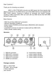
Dear Customer!<br />
Thank you for choosing our product.<br />
G <strong>LAB</strong> <strong>Amp</strong> <strong>Loop</strong> <strong>Adapter</strong> <strong>ALA</strong>-1 assures correct functioning of the effects<br />
connected to the amp effect loop. <strong>Adapter</strong> enables to adjust the signal level<br />
of the amp effect loop to sensitivity of connected effects. <strong>Adapter</strong> also<br />
resolves the high output impedance problem and the problem of ground loop<br />
arising from SEND and RETURN cables. This problems occurs in many of<br />
the guitar tube amp models what practically makes impossible to connect the<br />
effects placed in pedal board (connected with few meters long cables).<br />
Basic features<br />
- lossless transmission, with one cable, of SEND and RETURN signals<br />
independently from OUT and IN circuits of amp effect loop,<br />
- possibility to adjust signal level by boosting or attenuating the signal<br />
sent to the effects,<br />
- attenuation module with regulation up to -16 dB (/6),<br />
- boost module based on A class amp with regulation up to 14 dB (x5),<br />
- possibility to bypass the boost and attenuation modules,<br />
- high level of transmitted signal 18 dBu (17Vpp).<br />
Package contents<br />
<strong>ALA</strong>-1 adapter module<br />
<strong>Loop</strong> <strong>Adapter</strong> Cable<br />
2 Velcro fasteners<br />
<strong>User</strong> manual<br />
1
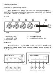
Structure<br />
<strong>Adapter</strong> consists of the JACK cable to be connected to the amp effect loop<br />
connectors and the adapter box containing SEND and RETURN connectors<br />
for the effects.<br />
1 - power supply indicator<br />
2 - BOOST control<br />
3 - BOOST module on/off switch<br />
4 - module order switches<br />
5 - ATTENUATION module on/off switch<br />
6 - ATTENUATION control<br />
7 - SEND out connector<br />
8 - RETURN in connector<br />
9 - LAC cable connector<br />
10 - 9V DC power supply connector<br />
2
1 - connector for <strong>ALA</strong>-1 adapter<br />
2 - GROUND LIFT switch<br />
3 - OUT connector<br />
4 - IN connector<br />
Power supply<br />
The <strong>ALA</strong>-1 should be supplied from external regulated 9V DC power supply,<br />
with capacity of 50 mA or more. It is recommended to use separated source<br />
(e.g. G <strong>LAB</strong> PB-1) in order to avoid ground loop. Before connecting check if<br />
the connector’s polarization is CTR – (center negative).<br />
The device is protected against opposite polarity. If this protection switches<br />
on it is needed to disconnect the power supply and wait few minutes before<br />
reactivation of the device.<br />
ATTENTION: Damages caused by improper power supply causes loss of the<br />
warranty.<br />
3
Connecting<br />
Signal IN connector should be connected to the effect loop SEND output and<br />
signal OUT connector should be connected to the amp RETURN input<br />
connector. GROUND LIFT switch enables to cut OUT connector ground what<br />
eliminates local ground loop (it is recommended to set in to ON position).<br />
<strong>Adapter</strong> cable is 6 meters long what enables to place the device in pedal<br />
board. Guitar effects (or the effect) should be connected to the adapter SEND<br />
and RETURN connectors.<br />
When signal doesn’t need level changes the switches should be set like on<br />
the picture below (both module order switches can be set to opposite<br />
position).<br />
If signal on the amp loop is too high the switches should be set like on the<br />
picture below.<br />
4
If signal on the amp loop is too low the switches should be set like on the<br />
picture below.<br />
Attenuation and boost module settings<br />
Attenuation and boost controls are placed on the front panel of the <strong>ALA</strong>-1.<br />
They can be set by using small flat screwdriver.<br />
If the effect features gain or peak indicator setting should be started either<br />
from the ATTENUATION module (if order switches are set to AT/BO) or from<br />
BOOST module (if order switches are set to BO/AT). For maximal utility<br />
signal (very often it is a clean tone) the regulator should be set to maximal<br />
value on which the peak indicator doesn’t light. After, the BOOST control<br />
(for order AT/BO) or ATTENUATION control (for order BO/AT) should be set<br />
to similar dB value in order to retain the signal level.<br />
If the effect doesn’t feature gain or peak indicator both controls should be set<br />
to minimum. Further, the signal level passing to the effect should be boosted<br />
either with ATTENUATION module control (for order AT/BO) or BOOST<br />
module control (for order BO/AT) up to the maximal value on which the signal<br />
overdrive doesn’t appear. After, the BOOST control (for order AT/BO) or<br />
ATTENUATION control (for order BO/AT) should be set to similar dB value in<br />
order to retain the signal level.<br />
5
Mounting<br />
Package contains two Velcro fasteners to fix the device to smooth surfaces.<br />
<strong>Adapter</strong> can be installed in the rack 19” using the G<strong>LAB</strong> 1U RMS FRONT<br />
PANEL.<br />
6
Technical parameters<br />
Dimensions width 110 mm<br />
depth<br />
height<br />
65 mm<br />
40 mm<br />
Weight<br />
Input impedance<br />
Output impedance<br />
Maximal level of transmitted signal *<br />
Bandwidth *<br />
0,63 kg<br />
400 kΩ<br />
200 Ω<br />
18 dBu (16 dBV, 18 Vpp)<br />
20Hz to 20 kHz @ - 0,35 dB<br />
* - with activated attenuation and boost modules<br />
Power supply<br />
9V DC 50 mA<br />
(8,7 do 9,4V regulated)<br />
7
DO NOT PLACE THIS PRODUCT INTO THE WASTE CONTAINER !<br />
This device is marked with a cross-lined waste container symbol<br />
according to 2002/96/EU Directive on Waste Electric and Electronic<br />
Equipment.<br />
Such marking informs that after usage equipment can not be<br />
trashed together with other household waste.<br />
An user obligation is to return wasted equipment to a party collecting wasted<br />
electric and electronic equipment. Parties collecting such equipment organise a<br />
system, including local collection points, shops and other units, allowing to return<br />
such equipment. This Directive assures an user free of charge utilisation of such<br />
delivered equipment.<br />
This device is made of materials which can be recycled or utilised after becoming<br />
out of use. Proper handling of wasted electric and electronic equipment reduce<br />
demand for row materials and contribute in avoiding harmful consequences for environment<br />
and health of people caused by dangerous components and not proper<br />
storing and utilising of such equipment.<br />
<strong>User</strong> <strong>Manual</strong>, Drawing No. G69INA00<br />
8