GSC-3 - G LAB
GSC-3 - G LAB
GSC-3 - G LAB

Create successful ePaper yourself
Turn your PDF publications into a flip-book with our unique Google optimized e-Paper software.
Version 2.5<br />
Table of contents<br />
IMPORTANT SAFETY INSTRUCTIONS 2<br />
FCC COMPLIANCE 2<br />
DECLARATION OF CONFORMITY 2<br />
PACKAGE CONTENT 3<br />
STRUCTURE 4<br />
SIGNAL’S PATH DIAGRAM 5<br />
BANKS, PRESETS AND MODIFIERS 5<br />
PRESET SELECTION 6<br />
BANK SELECTION 6<br />
SILENT TUNING (MUTE) 6<br />
PRESET PROGRAMMING 7<br />
LOOPS (LOOP1 TO LOOP6) PROGRAMMING 7<br />
AMP SETTINGS PROGRAMMING 7<br />
MIDI PROGRAM NUMBERS PROGRAMMING 7<br />
PRESET’S COPYING 8<br />
BANK COPYING 8<br />
CC CONTROLLERS’ VALUE PROGRAMMING 8<br />
SENDING ADDITIONAL PROGRAM CHANGE COMMANDS 9<br />
MODIFIERS PROGRAMMING 9<br />
TAP TEMPO 9<br />
SILENT SWITCHING FUNCTION 9<br />
SETTINGS 10<br />
LOOP BUTTON SETTINGS 10<br />
SWITCH BUTTON SETTINGS 11<br />
MIDI CHANNELS SETTING 12<br />
AMP CONTROLLING 12<br />
G <strong>LAB</strong> WP WAH-PAD CONNECTING 13<br />
G <strong>LAB</strong> TBWP TRUE BYPASS WAH-PAD CONNECTING 13<br />
CONNECTING AUX BANK UP/DOWN WITH MIDI IN FOOTSWITCH 13<br />
USB CONNECTING WITH PC 13<br />
AUX CONNECTOR 13<br />
MIDI 4 X LOOP-ER CONNECTING 14<br />
TECHNICAL PARAMETERS 14<br />
MIDI IMPLEMENTATION CHART 15<br />
1
Important safety instructions<br />
– Read these instructions and follow them.<br />
– Prevent this device against moisture or spilling liquid inside.<br />
– Clean only with dry cloth.<br />
– Do not install near any heat sources such as radiators, heat registers, stoves, or other apparatus<br />
producing a lot of heat<br />
– Protect the power supply cord from being walked on or pinched.<br />
– Only use attachments/accessories specified by the manufacturer.<br />
– Unplug this device during lighting storms or when unused for long periods of time.<br />
– Do no open device or its power supply casing.<br />
– The power supply adapter should be installed in the socket outlet and disconnection of the adapter<br />
should be easily accessible.<br />
– To completely disconnect from AC mains disconnect the power supply adapter from the AC receptacle.<br />
FCC Compliance<br />
This device complies with Part 15 of the FCC Rules. Operation is subject to the following two conditions: (1)<br />
this device may not cause harmful interference, and (2) this device must accept any interference received,<br />
including interference that may cause undesired operation.<br />
NOTE: This equipment has been tested and found to comply with the limits for a Class B digital device,<br />
pursuant to Part 15 of the FCC Rules. These limits are designed to provide reasonable protection against<br />
harmful interference in a residential installation. This equipment generates, uses and can radiate radio<br />
frequency energy and, if not installed and used in accordance with the instructions, may cause harmful<br />
interference to radio communications. However, there is no guarantee that interference will not occur in<br />
a particular installation.<br />
If this equipment does cause harmful interference to radio or television reception, which can be determined<br />
by turning the equipment off and on, the user is encouraged to try to correct the interference by one or<br />
more of the following measures:<br />
– Reorient or relocate the receiving antenna.<br />
– Increase the separation between the equipment and receiver.<br />
– Connect the equipment into an outlet on a circuit different from that to which the receiver is connected.<br />
– Consult the dealer for help.<br />
Declaration of Conformity<br />
Elzab Soft Sp. z o.o., ul. Kruczkowskiego 39, 41-813 Zabrze, Poland,<br />
declare under sole responsibility, that the following product:<br />
G <strong>LAB</strong>/<strong>GSC</strong>-3, <strong>GSC</strong>-2 – Guitar System Controller<br />
conforms with requirements of the EC Council Directives:<br />
● 2006/95/EEC Low Voltage Directive,<br />
● 2004/108/EEC Electromagnetic Compatibility,<br />
and holds CE mark. Above named product conforms with the following standards:<br />
● PN-EN 60065:2004 /EN 60065:2002/ Audio, video and similar apparatus - Safety requirements.<br />
● PN-EN 55103-1:2000 /EN 55103-1:1996/ Electromagnetic compatibility - Product family standard for<br />
audio, video, audio-visual and entertainment lighting control apparatus for professional use - Part 1:<br />
Emission<br />
● PN-EN 55103-2:2001 /EN 55103-2:1996/ Electromagnetic compatibility - Product family standard for<br />
audio, video, audio-visual and entertainment lighting control apparatus for professional use - Part 2:<br />
Immunity<br />
Arkadiusz Kocik<br />
President of the Elzab Soft Sp. z o.o. Board of Directors<br />
Copy of original EC declaration of conformity is available for download on our website<br />
http://www.glab.com.pl<br />
2
Dear Customer,<br />
Congratulations for choosing our G <strong>LAB</strong> product!<br />
Guitar System Controller (<strong>GSC</strong>) is the programmable switching device of effects’ loops (looper), the amp’s<br />
switcher by footswitch input and the MIDI devices’ controller in one. By pressing just a single footswitch<br />
(called preset) it enables:<br />
– to activate selected effects (connected to LOOP1 up to LOOP6 loops),<br />
– to set the amp channel (or the pre-amp one) and other amp’s functions controlled by its footswitch<br />
input,<br />
– to set by Program Change command the MIDI device’s program No. of work (at three MIDI devices<br />
e.g. effects’ processors).<br />
The presets are stored in 10 banks. Depending on the method of changing the banks there are available<br />
eight or ten presets in each bank. Controller posses presets programming function and presets and banks<br />
copying functions what enables quick “organising” of the presets in the banks. The <strong>GSC</strong> enables also to<br />
assign to its footswitches following functions instead of presets:<br />
– to switch on/off the loop (loop modifier),<br />
– to set the amp settings function (e.g. selecting a channel),<br />
– to select the program No. (or numbers) of MIDI device (devices).<br />
To avoid the incidental changing of the presets’ settings the controller is equipped with the memory access lock.<br />
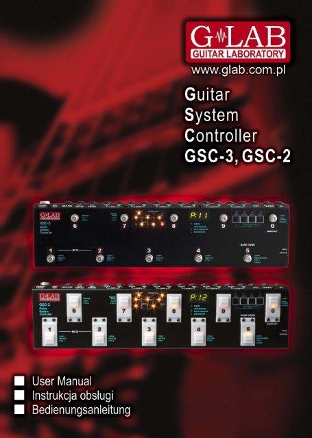
There are available two versions of the controller with different footswitches. The <strong>GSC</strong>-3 model posses metal<br />
footswitches with backligthed descriptions and the <strong>GSC</strong>-2 model posses silent, backlighted footswitches.<br />
Basic characteristics:<br />
– true passive signal path (except buffer),<br />
– true bypassed (by relay), high impedance input buffer,<br />
– TUNER output with the silent tuning function based on very high impedance circuit (no influence on<br />
a guitar signal),<br />
– six TRUE BYPASS loops for connecting effects (using electro-mechanical relays),<br />
– six 9V DC outputs (for supplying effects) in two separated sections (500mA each),<br />
– 2 outputs (2 lines each, latching type) for controlling the amp through its footswitch input,<br />
– MIDI output for controlling MIDI devices by Program Change and Control Change commands,<br />
– AUX connector for connecting extension modules,<br />
– USB connector for connecting to a PC, enabling downloading, editing and saving presets and<br />
settings, also firmware upgrades,<br />
– two modes of bank selection (by BANK UP / BANK DOWN footswitches or by pressing and holding<br />
presets’ footswitches) and an option “one bank mode”,<br />
– input for connecting a wah-wah effect pad (wah-pad) to control the system by placing the foot on<br />
the wah-wah,<br />
– external power supply with 4 meters long and flexible cable<br />
Package content<br />
Controller<br />
Power supply adapter<br />
Three 9V 40 cm cables<br />
Two 9V 80 cm cables<br />
One 9V 120 cm cables<br />
User’s Manual<br />
3
Structure<br />
On the inner side of the instruction cover are placed the pictures with elements numerated below.<br />
1 - IN – guitar signal input<br />
2 - TUNER – guitar tuner connector<br />
3 - OUT – amp’s signal output connector<br />
4 - SEND – effect’s loop output connector<br />
5 - RETURN – effect’s loop input connector<br />
6 - OUT SW1&2 and SW3&4 – output connectors for amp's switching by its footswitch input<br />
7 - WAH-PAD – wah-pad connector<br />
8 - MIDI OUT – MID output connector<br />
9 - POWER 12V DC – 12V DC power supply connector<br />
10 - OUT 9V DC – Effects’ power supply connectors<br />
11 - Presets selecting footswitches<br />
12 - Indicators<br />
13 - Display<br />
14 - Programming buttons<br />
15 - AUX connector<br />
16 - Memory access lock switch<br />
17 - USB connector<br />
BUFFER – Buffer indicator<br />
LOOP 1 to 6 – Indicators signalising switching on LOOPs<br />
POWER FAIL – Voltage failure indicator (voltage below 11.2V or above 12,8V)<br />
SWITCH 1 to 4 – SW1 to SW4 switch outputs’ status indicators<br />
LOCK – Memory access LOCK indicator<br />
LOOP – loops programming button and indicator<br />
SWITCH – amp’s controlling outputs button and indicator<br />
MIDI 1 – button and indicator for editing MIDI program of MIDI 1 device<br />
MIDI 2 – button and indicator for editing MIDI program of MIDI 2 device<br />
4
Signal’s path diagram<br />
Guitar signal, thru very high impedance (>10 MΩ) tuner buffer, is transmitted to TUNER output. It enables<br />
using of the tuner during playing.<br />
Controller features a switchable, true bypass input buffer circuit. Buffer which’s input impedance is consistent<br />
with tube amps boost the guitar signal power (without the voltage increase).<br />
Adding the buffor between the guitar and the effect can improve guitar sound (due to low input impedance<br />
many of the effects change the guitar tone) and in case of using long cables (between the controller and<br />
the amp) it enables to avoid high tones loss caused by cables’ parasitic capacitance appearing when all<br />
the effects are switched off.<br />
SEND outputs should be connected with IN effects inputs and RETURN inputs should be connected with<br />
OUT outputs of particular effects. MUTE block silents the signal during the quiet tunning.<br />
Controller has six 9V DC outputs for supplying the effects in two fully separated sections (500mA each).<br />
Before plugging the power supply the pin polarization coincidence should be checked.<br />
Banks, presets and modifiers<br />
Controller enables to program 10 presets (or 8 ones) in each of its 10 banks. There is information on the<br />
display about the bank and preset numbers. Banks and presets have got numbers from 0 to 9 range.<br />
bank number 2<br />
preset mode<br />
preset number 3<br />
The P character in front of double dot says that the given footswitch in the given bank is a preset. The L<br />
character says that the given footswitch is a loop modifier (similarly S character for a SWITCH modifier and<br />
n character for a MIDI modifier). The loop modifier switches on and off the selected effects’ loop. The<br />
SWITCH modifier sets the amp’s channel. The MIDI modifier sends the Program Change and/or Control<br />
Change MIDI commands to selected MIDI devices. Such solution enables to program banks only with<br />
presets to switch all the system just by pressing a single footswitch and to program the banks where<br />
5
particular footswitches perform the selected functions e.g. to switch on the single effect, to set the amps<br />
channel. Also it is possible to program some banks where a part of footswitches are presets and the other<br />
are modifiers.<br />
Below you will find the example of using presets and modifiers.<br />
Preset selection<br />
Press shortly (less then 1 second) the preset footswitch numbered from 1 to 5 (in the cb1 mode banks<br />
change from 0 to 9; in the cb2 mode banks change from 1 to 4 or from 6 to 9).<br />
Bank selection<br />
At the cb1 mode (pressing and holding preset footswitch).<br />
Press and hold (more then 1 second) the desired preset footswitch numbered from 0 to 9.<br />
During switching there will be activated for 1 second the preset adequate to the previously selected bank.<br />
Choosing this method enables to use 10 presets in each bank. It is recommended to organise presets in<br />
banks in such a way that all necessary presets used in a particular song will be located into just one bank.<br />
At the cb2 mode (using BANK UP / BANK DOWN buttons).<br />
Select the bank number using BANK UP (footswitch 0) or BANK DOWN (footswitch 5) and then press the<br />
preset footswitch (from range 1 to 4 or 6 to 9).<br />
Till the moment the preset footswitch is pressed the previous preset is active. It enables switching presets<br />
from the different banks while a song is played.<br />
Choosing this method enables to use 8 presets in each bank.<br />
To escape from the bank selecting function press and hold 0 or 5 footswitch longer then 1 second.<br />
At the cb3 mode (directly by using BANK UP/BANK DOWN footswitches for firmware 2.20 and higher).<br />
At this mode BANK UP and BANK DOWN footswitches cause correspondingly lowering and increasing<br />
bank number with immediate preset recalling (preset number in bank remains unchanged).<br />
Silent tuning (MUTE)<br />
Press simultaneously the footswitch No. 1 and 2 (blinking tun text will appear on the display).<br />
To exit from MUTE press the preset footswitch intended to be used.<br />
It is possible to define the footswitch No. 6 as a footswitch activating silent tuning mode MUTE (see Loop<br />
button settings, footswitch No. 7).<br />
6
Preset programming<br />
A preset is defined by:<br />
– switched on effects (connected to LOOP1 to LOOP6) and buffer switched on or off;<br />
– amp’s setting (amp channel and/or effect selecting) controlled by SW1 to SW4 outputs;<br />
– MIDI Program Change numbers (and Control Change commands) transmitted to MIDI devices.<br />
Loops (LOOP1 to LOOP6) programming<br />
a) Select bank and preset.<br />
b) Memory access lock switch to UNLOCK position (LOCK indicator not lit).<br />
c) Press LOOP button (LOOP indicator and preset number start to blink).<br />
d) Check if P character is displayed before the double dot. If not set it by footswitch No. 7 (PRESET<br />
MODE)<br />
e) By presets footswitches 1 to 5 and 0 set loops (effects) which should be active (indicators LOOP 1<br />
to 6 lit mean effects are activated). Switch on/off the buffer by footswitch No. 6 (BUFFER indicator<br />
lit means the buffer is active).<br />
f) Press LOOP button to save. Displaying text Stored confirm saving.<br />
In case of necessity of escape without saving while the point d) or e) it should be pressed SWITCH or<br />
MIDI 1 or MIDI 2 button.<br />
REMARK:<br />
In case of not plugging in a connector to a particular effect’s loop RETURN the signal will skip such a loop<br />
despite of activating this loop. It allows to use presets despite of not connecting effects to such a loop.<br />
Amp settings programming<br />
a) Select bank and preset.<br />
b) Memory access lock switch to UNLOCK position (LOCK indicator not lit).<br />
c) Press SWITCH button (SWITCH indicator and preset number start to blink).<br />
d) By footswitches 1 to 4 set SWITCH outputs (SW1 to SW4 indicators signalise amp settings).<br />
e) Press SWITCH button to save. Displaying text Stored confirm saving.<br />
In case of necessity of escape without saving while the point d) it should be pressed LOOP or MIDI 1 or<br />
MIDI 2 button.<br />
MIDI program numbers programming<br />
The controller enables to control three MIDI devices (MIDI 1, MIDI 2 and MIDI 3) by the Program Change<br />
command. Before programming, the MIDI channels should be set (see: MIDI channel setting).<br />
a) Connect MIDI cable between MIDI OUT output connector and MIDI IN input connector of the<br />
controlled device.<br />
b) Select bank and preset.<br />
c) Memory access lock switch to UNLOCK position (LOCK indicator not lit).<br />
d) Press MIDI 1 button (MIDI 1 indicator will start to blink). Actual program No. or text unused (what<br />
means that command is not send) will appear on display.<br />
e) Enter program No. using footswitches (e.g. for program No. 24 press footswitch No. 2 and then<br />
footswitch No. 4). If you don’t want to send Program Change command in this preset press<br />
footswitch No. 0 and hold for minimum 1 second (text unu will appear on display).<br />
Available program numbers are from 1 to 128 (transmitted values from 0 to 127). The text Err<br />
means the number is out of the range.<br />
f) Press MIDI 1 button to save. Displaying text Stored confirms saving.<br />
In case of necessity of escape without saving while the point e) it should be pressed LOOP or SWITCH<br />
button.<br />
7
For MIDI 2 device do it in similar way and for MIDI 3 device the MIDI 1 and MIDI 2 buttons should be pressed<br />
simultaneously. The MIDI 3 program number can be programmed in this way only when the setting at LOOP<br />
button (No. 6 footswitch) is set to n3p (MIDI 3, only Program Change command).<br />
Preset’s copying<br />
a) Select preset to copy.<br />
b) Memory access lock switch to UNLOCK position (LOCK indicator not lit).<br />
c) Press at simultaneously LOOP and MIDI 2 buttons (LOOP and MIDI 2 indicators start to blink and<br />
SWITCH and MIDI 1 indicators start to lit).<br />
d) Switch bank (if necessary) and choose preset No. where to past copied preset.<br />
e) Press simultaneously LOOP and MIDI 2 buttons to save preset. Text Stored confirms saving.<br />
In case of necessity of escaping without saving while in the point d) should be pressed SWITCH or MIDI 1<br />
button.<br />
Bank copying<br />
a) Select any preset of the bank to copy.<br />
b) Memory access lock switch to UNLOCK position (LOCK indicator not lit).<br />
c) Press simultaneously SWITCH and MIDI 1 buttons (SWITCH and MIDI 1 indicators start to blink<br />
and LOOP and MIDI 2 indicators start to lit).<br />
d) Choose a bank where to past copied bank.<br />
e) Press simultaneously SWITCH and MIDI 1 buttons to save bank. Text Stored confirms saving.<br />
In case of necessity of escaping without saving while in the point d) should be pressed LOOP or MIDI 2<br />
button.<br />
CC controllers’ value programming<br />
The <strong>GSC</strong> enables to control MIDI 3 device by Control Change commands. Before value programming at<br />
LOOP button settings (footswitch No. 6) set transmitting Control Change commands (m3c), and set<br />
controllers’ numbers (see: Controllers’ numbers setting for Control Change commands).<br />
a) Select bank and preset.<br />
b) Memory access lock switch to UNLOCK position (LOCK indicator not lit).<br />
c) Press simultaneously MIDI 1 and MIDI 2 buttons (MIDI 1 and MIDI 2 indicators start to blink).<br />
The text ctl will appear on display.<br />
d) Short pressing footswitches numbered from 1 to 7 will effect in short displaying text CC and the controllers<br />
No. e.g. 81 and after actual value of the controller will be displayed. Pressing No. 0 footswitch<br />
displays the actual program No. transmitted to the MIDI 3 device by Program Change command.<br />
e) Press and hold for longer than 1 second the controller footswitch intended to be changed (blinking<br />
“0” will appear on display).<br />
f) Enter the value of controller using footswitches. The controller value can be from 0 to 127 range,<br />
unused or toggle. Press and hold for longer than 1 second footswitch No. 0 to set the controller<br />
unused (not to be transmitted). To set the toggle function press and hold for longer than 1 second<br />
the footswitch No. 5. Toggle function means that successive pressing the footswitch toggles transmitted<br />
values 0 and 127 and effects in switching on/off a chosen parameter or a function of MIDI 3<br />
device. In case when we programmed the footswitch as a MIDI modifier and the only transmitted<br />
command is toggle value controller we get the footswitch e.g. switching on and off a single effect at<br />
multieffect device. In this way we get the functionality of such a footswitch identical with loop<br />
modifier (for a single effect as stompbox connected to a loop). When at other preset or modifier the<br />
given controller is transmitted with value 0 or 127 the toggle function will consider the previously<br />
transmitted value.<br />
g) Press MIDI 1 (or MIDI 2) button to accept the value. If you want to edit the value of other controller<br />
operate according to point d) and e).<br />
8
h) Press simultaneously MIDI 1 and MIDI 2 buttons to save entered vales. Text Stored confirms saving.<br />
In case of necessity of escaping without saving while in the point d) should be pressed LOOP or<br />
SWITCH button.<br />
Sending additional Program Change commands<br />
Controller enables sending out four additional Program Change commands (named PC4 to PC7) instead<br />
of Control Change 4 to 7 commands. To use this option it is needed:<br />
– to set at LOOP button settings (footswitch No. 6) transmitting three Control Change and five<br />
Program Change (m3A) commands,<br />
– to set at SWITCH button settings the channel numbers for MIDI 4 to MIDI 7 instead of the controller<br />
numbers CTRL 4 to CTRL 7,<br />
– to enter the program numbers to send in place of the controller values CTRL4 do CTRL7. On<br />
display, in place of the “CC” and controller’s number, will appear the “PC” with the number of MIDI<br />
device to which will be sent the program number.<br />
Modifiers programming<br />
Modifiers enable to program the controller in such a way that the given footswitch in the chosen bank instead<br />
of preset function would serve one of the following functions:<br />
– switching on and off an effect connected to an effect loop (LOOP MODIFIER),<br />
– setting the amp at a chosen channel (SWITCH MODIFIER),<br />
– sends the Program Change and/or Control Change MIDI commands to selected MIDI devices (MIDI<br />
MODIFIER).<br />
To achieve it after selecting a bank and a footswitch which should be a modifier you have to enter Loops<br />
(LOOP1 to LOOP6) programming function and using footswitch No. 7 you have to select the modifier<br />
type: L – LOOP modifier, S – SWITCH modifier and n – MIDI modifier.<br />
For a LOOP modifier you should select the loop which should be switched on and off (toggled) by successive<br />
pressing this footswitch. It means that if a given LOOP is switched off pressing this footswitch will effect<br />
in switching LOOP on. When LOOP is switched on – pressing this footswitch will switch LOOP off. It is<br />
recommended to program LOOP modifiers only for single loops.<br />
For a SWITCH modifier you should enter Amp settings programming function and set states of lines<br />
SW1 to SW4 to achieve the desired amp settings. SWITCH modifier recalls desired amp settings so to<br />
switch e.g. between two channels it is needed to program two footswitches as SWITCH modifiers.<br />
For a MIDI modifier you should apply the same procedure considering that you can program footswitch to<br />
control one of MIDI devices (or more) and by Control Change commands one of the function of selected<br />
MIDI device. This is possible by using unused function (not transmitting a given command) and toggle<br />
function (for Control Change commands).<br />
Tap tempo<br />
The <strong>GSC</strong> with program version 2.24 enables to send tempo to one of three MIDI devices (MIDI 1, MIDI 2<br />
or MIDI 3). This function is activated in LOOP button settings by footswitch No. 5.<br />
After pressing a footswitch of any preset the next pressings of this footswitch will effect in sending the CC<br />
command No. 80 with value toggled between 0 and 127. The command is not transmitted when footswitch<br />
is a LOOP modifier. It is possible to program a footswitch to realise only the tap tempo function. For that<br />
purpose this footswitch should be programmed as a MIDI modifier without transmitting program numbers.<br />
You should remember that to enter the tap tempo you need to press the footswitch three times.<br />
Silent switching function<br />
Controller <strong>GSC</strong> futures silent switching function (CLICK PROTECTION) which can be set on one of five<br />
levels (from CP1 to CP5) in LOOP settings at footswitch No. 9. If the controller is connected between a guitar<br />
9
and an amp input it is recommended to set silent switching on level CP3 to CP5. In case when controller is<br />
connected to an amp effects loop it is recommended to set silent switching on level CP1 to CP3.<br />
In firmware version 2.23 and lower the silent switching works on level CP5.<br />
Settings<br />
Settings parameters have been divided between LOOP and SWITCH buttons. The setting parameters of<br />
MIDI channels transmission are assigned to the MIDI buttons. Factory settings in the tables below are<br />
bolded.<br />
LOOP button settings<br />
a) Memory access lock switch to LOCK position (pressed, LOCK indicator lit).<br />
b) Press and hold LOOP button then memory access lock switch to UNLOCK position (LOCK<br />
indicator stops lit). The LOOP indicator starts to blink and SWITCH, MIDI 1 and MIDI 2 indicators<br />
start to light. Text SP1 will appear on display.<br />
c) First pressing footswitches will effect in displaying status of particular settings, the next pressing<br />
effect in changing the status of particular settings.<br />
1<br />
cb0 change bank mode 0 – constantly selected bank No. 0<br />
cb1<br />
change bank mode 1 –changing the bank by pressing and holding (over 1<br />
second) footswitches;<br />
cb2<br />
change bank mode 2 – changing the bank by using BANK UP footswitch<br />
to increase or BANK DOWN footswitch to decrease a bank number<br />
change bank mode 3 – changing the bank by using BANK UP footswitch<br />
cb3* to increase or BANK DOWN footswitch to decrease a bank number with<br />
immediate recalling of the preset.<br />
2<br />
3<br />
4<br />
5<br />
6<br />
uP0<br />
uP1<br />
uP2<br />
uL1<br />
…<br />
uL6<br />
ot0<br />
ot1<br />
tt0<br />
tt1<br />
tt2**<br />
tt3**<br />
m3p<br />
m3c<br />
m3A<br />
wah-pad 0 – wah-pad not active<br />
wah-pad 1 – WP type wah-pad connected<br />
wah-pad 2 – TBWP type wah-pad connected<br />
wah loop 1 – wah-pad connected to the LOOP1 loop<br />
wah loop 6 – wah-pad connected to the LOOP6 loop.<br />
This setting is only important for adding to preset a wah-wah effect mode (Add).<br />
one time mode 0 – mode of transmitting Program Change commands<br />
always when a preset footswitch is pressed<br />
one time mode 1 - mode of transmitting Program Change commands only when<br />
a given preset footswitch is pressed for the first time<br />
tap tempo 0 – tap tempo function inactive<br />
tap tempo 1 – sending tap tempo (Ctrl Ch #80, 0/127) to MIDI1 device<br />
tap tempo 2 – sending tap tempo (Ctrl Ch #80, 0/127) to MIDI2 device<br />
tap tempo 3 – sending tap tempo (Ctrl Ch #80, 0/127) to MIDI3 device<br />
midi 3 program change – only Program Change command can be<br />
transmitted to a MIDI 3 device<br />
midi 3 control change and program change – to MIDI 3 device can be sent seven<br />
Control Change and one Program Change commands<br />
midi 3 control change and program change – to MIDI 3 device can be sent three<br />
Control Change and one Program Change commands and there is a possibility to<br />
send four Program Change commands to devices MIDI 4 to MIDI 7 (PC4 to PC7)<br />
10
tu1<br />
tuner 1 – a guitar tuner connected to TUNER output, activated by pressing<br />
simultaneously footswitch No 1 and 2<br />
7<br />
tu2<br />
tuner 2 – used tuner built in MIDI processor, (recalling program No. 100 with<br />
muted signal)<br />
tu3 tuner 3 – tuner connected to the TUNER output, only by pressing footswitch No. 6<br />
8<br />
tu4<br />
AF1*<br />
AF2*<br />
CP1**<br />
tuner 4 – using built-in tuner in MIDI processor, (recalling program No. 100 with<br />
muted signal) activation by pressing footswitch No 6<br />
AUX function 1 – AUX output function No. 1 – controlling AUX 2 x LOOP,<br />
AUX A/B SWITCH, AUX SWITCH 5&6 OUT modules<br />
AUX function 2 – AUX output function No. 2 – working with AUX BANK<br />
UP/DOWN with MIDI IN footswitch<br />
click protection 1 – level 1 (the lowest one) of muting the loop switching clicks<br />
9<br />
…<br />
CP5**<br />
click protection 5 – level 5 (the highest one) of muting the loop switching<br />
clicks (same as silent switching in firmware version 2.23 or lower)<br />
* - from firmware version 2.20 ** - from firmware version 2.24<br />
d) Pressing the LOOP button will effect in saving settings (text Stored confirms saving).<br />
In case of necessity of escaping without saving while in the point c) should be pressed SWITCH, MIDI 1 or<br />
MIDI 2 button.<br />
SWITCH button settings<br />
Controller enables to transmit 7 controllers’ numbers. In settings are programmed controllers’ numbers and<br />
for a particular preset (or a MIDI modifier) are programmed values of controllers which should be transmitted.<br />
a) Memory access lock switch to LOCK position (pressed, LOCK indicator lit).<br />
b) Press and hold SWITCH button and while it is pressed switch memory access lock to UNLOCK<br />
position (LOCK indicator stops to light). SWITCH indicator will start to blink and LOOP, MIDI 1 and<br />
MIDI 2 indicators will start to light. Text SP2 will appear on display<br />
c) Short pressing footswitches numbered from 1 to 7 will effect in displaying actual controller number<br />
assigned to a particular footswitch. Short pressing of one of the footswitches from No. 1 to No. 7<br />
will display the current controller number (or MIDI channel number on the mode of sending seven<br />
Program Change commands) assigned to the particular footswitch.<br />
d) Press and hold for longer than 1 second the controller footswitch intended to be changed (blinking<br />
“0” will appear on display). A controller number can be from 0 to 127 range. Press intended<br />
numbered footswitches.<br />
e) Footswitch No. 8 (by successive pressings) enables to set the SWITCH 1 to 4 working modes<br />
according to the table below.<br />
8<br />
SF1<br />
SF2<br />
SF3<br />
SF4*<br />
SF5*<br />
SWITCH function 1 –SWITCH 1 to 4 outputs in latching mode (closed or<br />
open state)<br />
SWITCH function 2 – SWITCH 1 to 4 outputs in pulse mode (closed for 80 ms)<br />
SWITCH function 3 –SWITCH 1 to 4 outputs in momentary switch mode (closed<br />
for 80 ms)<br />
SWITCH function 4 – SWITCH 1, 2 and 3 outputs in the pulse mode (closed for<br />
80 ms), the SWITCH 4 output in the momentary switch mode (closed for 80 ms)<br />
SWITCH function 5 – SWITCH 1 and 2 outputs in the pulse mode (closed for 80<br />
ms), the SWITCH 3 and 4 outputs in themomentary switch mode (closed for 80 ms)<br />
* - from firmware version 2.25<br />
11
f) Pressing SWITCH button confirms entered number. To edit numbers of other controllers you should<br />
operate according to the points c), d) and e).<br />
g) Press SWITCH button to save settings (text Stored confirms saving).<br />
In case of necessity of escaping without saving while in the point c) or e) should be pressed LOOP, MIDI 1<br />
or MIDI 2 button.<br />
MIDI channels setting<br />
Controller enables to control (by a Program Change command) three MIDI devices marked as MIDI 1, MIDI 2<br />
and MIDI 3. To set the connection between desired device at the <strong>GSC</strong> and connected device should be set<br />
the same MIDI channel.<br />
MIDI 1 device channels setting:<br />
a) Memory access lock switch to LOCK position (pressed, LOCK indicator lit).<br />
b) Press and hold MIDI 1 button and while it is pressed switch memory access lock to UNLOCK<br />
position (LOCK indicator stops to light, MIDI 1 indicator starts to blink). The actually used channel<br />
No. will appear on display.<br />
c) Enter the desired channel No. by footswitches.<br />
d) Press the MIDI 1 button to save settings (text Stored confirms saving).<br />
In case of necessity of escaping without saving while in the point c) should be pressed LOOP or SWITCH<br />
button.<br />
For MIDI 2 device do it in similar way and for MIDI 3 device the MIDI 1 and MIDI 2 buttons should be<br />
pressed simultaneously.<br />
Amp controlling<br />
The SW1 to SW4 outputs are used to control the amp functions. Depending on your amp features it can be<br />
channels switching or on/off switching of the reverb, effects loop, BOOST function etc.<br />
Many of the amp models are equipped with ¼’ Jack foot pedal input. If your amp posses such input (or<br />
inputs) please contact your dealer or amp manufacturer service to know if your amp can be controlled<br />
directly by relay output (with typical Jack-Jack mono or stereo cable or with Y type cable).<br />
ATTENTION! DO NOT CONNECT THE SWITCHNG OUTPUTS (SW1&2 and SW3&4) WITH THE<br />
EXTERNAL SWITCHING INPUTS OF THE MESA BOOGIE AMPS. To connect the <strong>GSC</strong> with this type of<br />
amps use G <strong>LAB</strong> MIDI AMP CONTROLLER MAC-4.4.<br />
On the www.glab.com.pl is placed a list of amp models with their connection mode. G <strong>LAB</strong> offers dedicated<br />
cables and adapters for particular amps.<br />
Controller enables the SWITCH outputs to work on SF1 – latching type mode, SF2 – pulse mode and<br />
SF3 – momentary switch mode (see SWITCH button settings, footswitch No 8). Mostly used mode is the<br />
SF1 - latching type mode. In this mode the indicators SWITCH 1 to 4 lit what means contact short-circuit of<br />
corresponding relay. Other modes are applied in selected amp models for which is required other<br />
functionality of outputs. In case of controlling the amp with momentary switch input (SF3 mode) the amp<br />
should obligatorily posses the switch which enables switching the functions in order to synchronize<br />
controller and amp states.<br />
SW1&2 and SW3&4 outputs’ circuit scheme is shown below.<br />
SWITCH outputs are galvanically separated to avoid grand loops. It is recommended to use the connectors<br />
with plastic jackets to avoid occidental connection with signal grand.<br />
12
G <strong>LAB</strong> WP Wah-Pad connecting<br />
The wah-pad enables switching on a wah-wah effect by placing a foot on it and switching off a wah-wah<br />
effect by removing a foot. The wah-pad should be placed beneath a wah-wah effect and the wah-pad’s<br />
connector should be plugged into WAH-PAD connector. A wah-wah effect’s input and output should be connected<br />
to LOOP1 up to LOOP6 connectors. Wah-pad settings are described at “LOOP button settings”. At<br />
LOOP button settings footswitch No. 2 set uP1 and set the loop No. to which your wah-wah effect is<br />
connected for footswitch No. 3.<br />
Depending on WAH PAD MODE parameter the wah-pad enables to activate in any preset of given bank<br />
the loop your wah-wah effect is connected (“adding a wah-wah” mode) or to switch to preset No. 9 in given<br />
bank (“changing preset” mode). To program the WAH PAD MODE parameter press SWITCH button (“Amp<br />
settings programming” function) and use footswitch No. 5. Add means “adding a wah-wah” mode, Pr9 means<br />
“changing preset” mode. In case of using “changing preset” mode you need to set at a loop to which a wah-wah<br />
effect is connected in a No. 9 preset of a given bank. Such solution enables to simultaneously control other<br />
effects and amp by placing a foot on the wah-pad. It is recommended to use “changing preset” mode only for<br />
presets, or presets and modifiers with exclusion of modifiers transmitting Control Change type commands.<br />
G <strong>LAB</strong> TBWP True Bypass Wah-Pad connecting<br />
The TBWP is equipped with SEN (mini Jack) output which enables to connect it to the <strong>GSC</strong> (see diagram<br />
below).<br />
Connecting it enables for given banks to switch current preset to preset No. 9 when your wah-wah effect is<br />
active. At LOOP button settings footswitch No. 2 should be set uP2 and in banks we intend to use in this<br />
way the WAH PAD MODE parameter should be set to Pr9.<br />
Connecting AUX BANK UP/DOWN with MIDI IN footswitch<br />
AUX BANK UP/DOWN with MIDI IN footswitch enables working in the mode of changing the banks by<br />
using BANK UP i BANK DOWN footswitches with ten presets in bank and also enables controlling the<br />
<strong>GSC</strong> by other device sending the Program Change commands. Before connecting it is needed to set AF2<br />
at LOOP button settings (footswitch No. 8). The module should be connected to the AUX connector. MIDI<br />
receiving channel should be set on the rotatable switch situated on the left side of the module. The module<br />
receives Program Change commands in the range form 1 to 100 (program No. 100 corresponds with<br />
preset No. P00).<br />
USB connecting with PC<br />
Controller posses USB interface to connect with PC what enables fast programming of the controller.<br />
On G <strong>LAB</strong> web site is available the G2SOFT program that enables reading from controller, writing to controller,<br />
saving to the file, reading from the file the single or all of presets, banks and settings also screen edition<br />
of all the parameters, presets and banks copying, printing of presets’ tables etc.<br />
The G2SOFT works on Windows 98/ME/XP/2000/VISTA/7. <strong>GSC</strong> should be connected with PC by USB A-B<br />
cable. The program and necessary tools with installation procedure are available on www.glab.com.pl .<br />
PC connection enables also <strong>GSC</strong> firmware upgrade. It is recommended to check on the G <strong>LAB</strong> web site if<br />
the newer version of the firmware with functionality changes is available.<br />
AUX connector<br />
Controller posses AUX connector for additional modules to extend the controller functionality e.g.<br />
AUX A/B SWITCH (to switch the input signal from two guitars). The actual list of modules you’ll find in<br />
accessories for the controller at www.glab.com.pl.<br />
13
MIDI 4 X LOOP-er connecting<br />
MIDI 4 X LOOP-er (M4L) enables to increase the number of effects controlled by <strong>GSC</strong>.<br />
When the controller is placed “in front of” (between guitar and amp input) it is recommended to use the<br />
M4L as controlled switcher of the effects connected to amp FX LOOP.<br />
When the <strong>GSC</strong> is connected to amp FX LOOP the M4L enables to control the effects placed “in front of”<br />
(between guitar and amp input).<br />
The control is realized via MIDI connection by Program Change or Control Change commands. It enables<br />
to choose the way of controlling either by recalling the program setting the loops state or by Control<br />
Change commands (switching of individual loops).<br />
Technical parameters<br />
Dimensions: width 441 mm<br />
depth<br />
125 mm (without connectors)<br />
height<br />
60 mm<br />
Weight<br />
1.9 kg<br />
Buffer input impedance<br />
1 MΩ<br />
Buffer transmitted signal<br />
15 dBu<br />
Buffer output impedance<br />
3 kΩ<br />
Tuner buffer input impedance<br />
10 MΩ<br />
Power supply<br />
12V DC 2A<br />
14
MIDI implementation chart<br />
G <strong>LAB</strong> Guitar System Controller <strong>GSC</strong>-3 and <strong>GSC</strong>-2 rev. 2.11<br />
FUNCTION TRANSMITTED RECOGNISED<br />
Basic Channel<br />
Default 1,2,3 X<br />
Changed 1-16 X<br />
Mode<br />
Default<br />
Messages X X<br />
Altered<br />
Note Number X X<br />
True Voice X X<br />
Velocity<br />
Note ON X X<br />
Note OFF X X<br />
After Touch<br />
Keys X X<br />
Channels X X<br />
Pitch Bend X X<br />
Control Change<br />
X<br />
Prog Change O X<br />
System Excl. X X<br />
System Common<br />
Song Pos X X<br />
Song Sel X X<br />
Tune X X<br />
System real time<br />
Clock X X<br />
Commands X X<br />
Aux Messages<br />
Local ON/OFF X X<br />
All Notes OFF X X<br />
Active Sense X X<br />
Reset X X<br />
O: YES<br />
X: NO<br />
15
DO NOT PLACE THIS PRODUCT INTO THE WASTE CONTAINER !<br />
This device is marked with a cross-lined waste container symbol according<br />
to 2002/96/EU Directive on Waste Electric and Electronic Equipment.<br />
Such marking informs that after usage equipment can not be trashed<br />
together with other household waste.<br />
An user obligation is to return wasted equipment to a party collecting<br />
wasted electric and electronic equipment. Parties collecting such equipment organise a system,<br />
including local collection points, shops and other units, allowing to return such equipment. This<br />
Directive assures an user free of charge utilisation of such delivered equipment.<br />
This device is made of materials which can be recycled or utilised after becoming out of use.<br />
Proper handling of wasted electric and electronic equipment reduce demand for row materials<br />
and contribute in avoiding harmful consequences for environment and health of people caused<br />
by dangerous components and not proper storing and utilising of such equipment.<br />
Drawing No. G51INA0025<br />
16