Brush Type Manual - General Dynamics Global Imaging Technologies
Brush Type Manual - General Dynamics Global Imaging Technologies
Brush Type Manual - General Dynamics Global Imaging Technologies

Create successful ePaper yourself
Turn your PDF publications into a flip-book with our unique Google optimized e-Paper software.
Pancake Resolvers >> <strong>Brush</strong>less Motors >><br />
<strong>Brush</strong> <strong>Type</strong> DC Motors<br />
(800) 777-3393<br />
Model<br />
Peak Torque<br />
(oz-in)<br />
Motor Constant<br />
(Km)<br />
Torque @ 40 watts<br />
T=Km watts<br />
OD<br />
(in)<br />
Length<br />
(in)<br />
Weight<br />
(oz)<br />
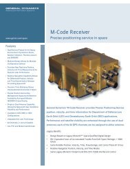
1500V-040 14 1.58 9.99 1.500 0.40 1.5<br />
1375V-062 22 2.67 16.89 1.700 0.45 1.9<br />
1500V-062 28 2.91 18.40 1.500 0.62 2.7<br />
Fig. 7 Example of three models using torque vs. power derating @ 40 watts<br />
W NL<br />
Speed<br />
Torque<br />
Current Limit Level<br />
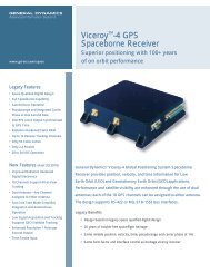
Fig. 7A Family of speed-torque curves.<br />
input. Model 1500V-040, while rated at a<br />
peak torque of 14 oz-in cannot meet torque<br />
requirements with a 40 watt input. Figure 7,<br />
under the torque calculation column, two<br />
other models exceeding the required torque<br />
can be selected.<br />
Motor selection can be made to optimize<br />
weight or configuration. Note the wide<br />
variations available in motor diameter, axial<br />
length and weight.<br />
This procedure illustrates the trade-offs normally<br />
encountered when derating because of<br />
power supply limits. In some situations, thermal<br />
considerations rather than power supply<br />
limits make derating necessary. Installation<br />
heat transfer paths and duty-cycles sometimes<br />
dominate selection criteria.<br />
11<br />
If a torque motor is derated for power<br />
input, the damping coefficient<br />
(Fo = Tp/ NLT )<br />
remains constant and therefore for all practical<br />
purposes a speed torque characteristic<br />
for a model can be drawn for any DC<br />
torque motor by plotting a straight line<br />
between the values for peak torque and noload<br />
speed. (Fig. 7A)<br />
Over-speed Operation<br />
An application sometimes calls for operating<br />
a motor above its normal maximum<br />
speed-torque curve.This presents some<br />
problems due to the fact that torque<br />
motors are designed for good commutation<br />
at slow speeds and high torques, therefore<br />
some points above the speed-torque curve<br />
are points where bad commutation and the<br />
resultant decrease in brush life occur. In<br />
order to avoid this eventuality, it is generally<br />
true that the motor should not be operated<br />
above the shaft power output that is represented<br />
by the following equation.<br />
www.axsys.com<br />
><br />
Matching Motors to REquirement