Brush Type Manual - General Dynamics Global Imaging Technologies
Brush Type Manual - General Dynamics Global Imaging Technologies
Brush Type Manual - General Dynamics Global Imaging Technologies

Create successful ePaper yourself
Turn your PDF publications into a flip-book with our unique Google optimized e-Paper software.
Pancake Resolvers >> <strong>Brush</strong>less Motors >><br />
<strong>Brush</strong> <strong>Type</strong> DC Motors<br />
Damping<br />
By manipulating Eq (7), the following equation<br />
for servo motor damping (F0) is<br />
derived.<br />
F 0 = 141.612 ( V P<br />
) 2 (8)<br />
R NLT<br />
(800) 777-3393<br />
Direct-Drive Systems<br />
Motor Transfer Function<br />
A DC torque motor can be represented by<br />
the following transfer function for simplified<br />
servo analysis.This transfer function<br />
ignores motor induction, friction and shaft<br />
resonances.<br />
Here V p /NLT is, of course, the volts per<br />
rad/sec of back EMF (the voltage that<br />
would be developed if the torque motor<br />
were used as a tachometer). R is armature<br />
resistance (ohms) and F 0 is the damping in<br />
oz-in per rad/sec.The restrictions imposed<br />
by Eq (7) and Eq. (8) are fundamental in setting<br />
up consistent specifications for high<br />
performance torque motors.<br />
If voltage and NLTare not available, Fo can<br />
be calculated using back EMF constant and<br />
torque sensitivity.<br />
Fo = Kb*Kt<br />
R<br />
1/K b<br />
=<br />
V T m S+1<br />
= speed<br />
V = voltage input<br />
K b = back EMF constant<br />
T m = mechanical time constant<br />
To include the effect of motor inductance,<br />
the transfer function is modified to include<br />
an additional term.<br />
=<br />
V<br />
1/K b<br />
(T m S+1) (T e S+1)<br />
T e = electrical time constant<br />
Direct Drive Systems<br />
V<br />
R<br />
E= K B<br />
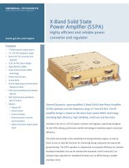
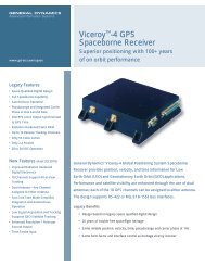
Fig. 2 Equivalent circuit of the <strong>Brush</strong> <strong>Type</strong> DC<br />
motor. Here L/R constitutes the electrical time<br />
constant. The component L, in the circuit, represents<br />
armature inductance, and can be minimized<br />
by careful design of the magnetic circuit.<br />
L<br />
This function assumes that the mechanical<br />
time constant is much larger than the electrical<br />
time constant and that friction is<br />
negligible.<br />
High response DC motors occasionally<br />
have mechanical time constants that<br />
approach their electrical time constants. In<br />
this case it is necessary to use the following<br />
transfer function.<br />
=<br />
1/K b<br />
V (T m T e S 2 +1) (T m T e) S+1<br />
5<br />
www.axsys.com<br />
>