INSTALLATION AND USE MANUAL Control Panel and ... - G.m.v.
INSTALLATION AND USE MANUAL Control Panel and ... - G.m.v.
INSTALLATION AND USE MANUAL Control Panel and ... - G.m.v.

Create successful ePaper yourself
Turn your PDF publications into a flip-book with our unique Google optimized e-Paper software.
<strong>INSTALLATION</strong> <strong>AND</strong> <strong>USE</strong><br />
<strong>MANUAL</strong><br />
<strong>Control</strong> <strong>Panel</strong> <strong>and</strong> Prewired system<br />
SETRONIK1<br />
For Electric <strong>and</strong> Hydraulic Lifts<br />
SEA SYSTEMS S.R.L<br />
<strong>Control</strong> <strong>Panel</strong>s, Push button panels <strong>and</strong> Prewired systems for lifts<br />
Street San Carlo 13 - 20010 Bareggio - Milano - ITALY<br />
Tel: +39 02 90 36 34 99 - Fax: +39 02 90 36 35 00<br />
Internet: www.seasystems.it - e-mail: sea@seasystems.it<br />
MSTK12-GB<br />
Rev.01<br />
30/12/05
SEA SYSTEMS<br />
<strong>INSTALLATION</strong> <strong>AND</strong> <strong>USE</strong> <strong>MANUAL</strong><br />
CONTROL PANEL <strong>and</strong> PREWIRED SYSTEM STK1<br />
For Electric <strong>and</strong> Hydraulic Lifts<br />
MSTK12-GB<br />
Rev.01<br />
30/12/05<br />
INTRODUCTION<br />
Our compliments for choosing the SETRONIK1 controller as the controller for your lift.<br />
Please carefully read this booklet so that you will be able to underst<strong>and</strong> all the qualities of<br />
this device <strong>and</strong> its potential.<br />
The SETRONIK1 family controllers are microprocessor-controlled controllers specially<br />
designed for the control of 1 Speed, 2 Speeds <strong>and</strong> Variable Speed, Hydraulic <strong>and</strong> Rope<br />
Lifts operating in APB, Simplex (up <strong>and</strong>/or down collective), Duplo <strong>and</strong> Pick-Up operation.<br />
The STK2-PM programmer allows to set a secret Access Code, know the conditions the lift<br />
is operating in, which <strong>and</strong> how many times failures <strong>and</strong> malfunctions have occurred,<br />
control the lift <strong>and</strong> doors motion <strong>and</strong> modify the operating characteristics of the lift itself.<br />
Several functions specific to a particular lift can be programmed without having to act on<br />
the <strong>Control</strong>ler wiring.<br />
As far as the operating Diagnostics is concerned, help is provided by the failure <strong>and</strong><br />
malfunction indications on the Programmer displays <strong>and</strong> by the indications<br />
supplied by the board LEDs.<br />
Warning<br />
Since our products are in constant evolution, all information contained in this manual can<br />
be modified by SEA SYSTEMS without notice.<br />
In the case of special lifts, any accessory documentation relating to additional or modified<br />
functions is provided.<br />
SETRONIK1 Pagina 2 di 54
SEA SYSTEMS<br />
<strong>INSTALLATION</strong> <strong>AND</strong> <strong>USE</strong> <strong>MANUAL</strong><br />
CONTROL PANEL <strong>and</strong> PREWIRED SYSTEM STK1<br />
For Electric <strong>and</strong> Hydraulic Lifts<br />
MSTK12-GB<br />
Rev.01<br />
30/12/05<br />
TABLE OF CONTENTS<br />
1. FUNCTIONAL CHARACTERISTICS ................................................... 5<br />
2. <strong>INSTALLATION</strong>..................................................................................... 6<br />
2.1. GENERAL NOTES.........................................................................................................7<br />
2.2. SAFETY RULES............................................................................................................8<br />
2.3. GLOSSARY ..................................................................................................................8<br />
2.4. PRELIMINARY OPERATIONS...........................................................................................9<br />
2.5. FIXING <strong>AND</strong> CONNECTION OF THE CONTROL PANEL ......................................................10<br />
2.6. FIXING <strong>AND</strong> CONNECTION IN THE SHAFT.......................................................................11<br />
2.7. FIXING <strong>AND</strong> CONNECTION ON THE CAR ROOF ................................................................14<br />
2.8. INSULATION TEST ......................................................................................................23<br />
2.9. SYSTEM COMMISSIONING ...........................................................................................24<br />
3. PROGRAMMING................................................................................. 25<br />
3.1 PROGRAMMER CONNECTION (STK2-PM) ....................................................................25<br />
3.2. EXAMPLE OF PROGRAMMER <strong>USE</strong> .................................................................................26<br />
3.3. PROGRAMMING THE CUSTOMER SECRET ACCESS CODE...............................................27<br />
3.4. PARAMETERS STORING. .............................................................................................28<br />
3.5. PROGRAMMING THE LIFT, OPERATION, SELECTOR........................................................29<br />
3.6. PROGRAMMING THE MAIN FLOOR, PARKING FLOOR, PREFERENTIAL FLOOR, FIREMEN <strong>AND</strong><br />
FIRE-FIGHTING FLOOR, DUPLO VERTICAL RISE FLOORS..................................................30<br />
3.7. PROGRAMMING THE OPERATOR..................................................................................31<br />
3.8. PROGRAMMING MAX FLOOR RE-LEVELLINGS, POSITION INDICATIONS. ............................32<br />
3.9. PROGRAMMING OF SPEED <strong>AND</strong> STOP MODE DURING INSPECTION, MOVABLE PLATFORM,<br />
ADVANCE DOORS OPENING, RE-LEVELLING, GONG .......................................................33<br />
3.10. PROGRAMMING OF OVERLOAD CONTACT...................................................................34<br />
3.11. PROGRAMMING OF SERVICES. ..................................................................................35<br />
3.12. SHAFT PROGRAMMING: ............................................................................................36<br />
3.13. PROGRAMMING OF TIMERS:......................................................................................37<br />
3.14. INPUT PROGRAMMING: .............................................................................................38<br />
3.15. OUTPUT PROGRAMMING: .........................................................................................39<br />
4. DIAGNOSIS......................................................................................... 40<br />
4.1. LIFT STATUS DISPLAY ................................................................................................40<br />
4.2. DISPLAY <strong>AND</strong> CANCELLATION OF FAILURES / MALFUNCTIONS.........................................41<br />
4.3. COUNT OF RUNS <strong>AND</strong> RE-LEVELLINGS PERFORMED. .....................................................42<br />
4.4. COMM<strong>AND</strong>S FOR LIFT OPERATION IN THE MACHINE ROOM: .............................................43<br />
4.5. LED SIGNALLING LEGEND OF CARDS STK1-B, STK1-E <strong>AND</strong> AL01................................44<br />
4.6. ERROR CODE LEGEND ...............................................................................................47<br />
SETRONIK1 Pagina 3 di 54
SEA SYSTEMS<br />
<strong>INSTALLATION</strong> <strong>AND</strong> <strong>USE</strong> <strong>MANUAL</strong><br />
CONTROL PANEL <strong>and</strong> PREWIRED SYSTEM STK1<br />
For Electric <strong>and</strong> Hydraulic Lifts<br />
MSTK12-GB<br />
Rev.01<br />
30/12/05<br />
5. MAINTENANCE ................................................................................ 50<br />
5.1. BATTERY REPLACEMENT.............................................................................................50<br />
5.2. SHAFT SENSORS........................................................................................................50<br />
5.3. STK1-B BASIC ELECTRONIC BOARD REPLACEMENT .....................................................51<br />
5.4. CS1 SAFETY CIRCUIT REPLACEMENT ..........................................................................52<br />
6. BASIC TROUBLESHOOTING PROCEDURES.................................. 53<br />
6.1. ALARMED CARD (ALL LED ON)....................................................................................53<br />
6.2. ERRONEUS READOUT OF THE SHAFT SENSORS .............................................................53<br />
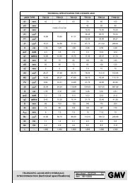
7. TECHNICAL DATA ............................................................................. 54<br />
SETRONIK1 Pagina 4 di 54
SEA SYSTEMS<br />
<strong>INSTALLATION</strong> <strong>AND</strong> <strong>USE</strong> <strong>MANUAL</strong><br />
CONTROL PANEL <strong>and</strong> PREWIRED SYSTEM STK1<br />
For Electric <strong>and</strong> Hydraulic Lifts<br />
MSTK12-GB<br />
Rev.01<br />
30/12/05<br />
1.FUNCTIONAL CHARACTERISTICS<br />
LIFT TYPES<br />
- ROPE 1 - 2 SPEEDS , ACVV , VVVF<br />
- HYDRAULIC : DIRECT , STAR DELTA , SOFT STARTER , SOFT STOP, SCC,<br />
ELECTRONIC VALVES<br />
OPERATIONS<br />
NUMBER OF STOPS<br />
DOOR CONTROL<br />
VARIOUS CONTROLS<br />
CAR <strong>AND</strong> L<strong>AND</strong>ING<br />
SIGNALS ( 24V. )<br />
SHAFT<br />
EMERGENCY<br />
- APB FOR INDIVIDUAL LIFT<br />
- DOWN COLLECTIVE SIMPLEX<br />
- DOWN-UP COLLECTIVE SIMPLEX<br />
- DUPLO<br />
- PICK UP<br />
- FOR APB <strong>AND</strong> DOWN COLLECTIVE:<br />
6 BASIC STOPS / 6 SERVICES<br />
EXTENSION OF 6 STOPS \ 6 SERVICES (TOTAL 12 STOPS \ 12 SERVICES)<br />
- FOR UP <strong>AND</strong> DOWN COLLECTIVE:<br />
4 BASIC STOPS \ 4 SERVICES<br />
EXTENSION 4 STOPS \ 4 SERVICES (TOTAL 8 STOPS \ 8 SERVICES)<br />
- <strong>MANUAL</strong> ON L<strong>AND</strong>INGS <strong>AND</strong> CAR<br />
- <strong>MANUAL</strong> ON L<strong>AND</strong>INGS <strong>AND</strong> WITHOUT DOORS IN THE CAR – BY SAFETY<br />
CELL<br />
- <strong>MANUAL</strong> ON L<strong>AND</strong>INGS <strong>AND</strong> AUTOMATIC IN THE CAR<br />
- AUTOMATIC ON L<strong>AND</strong>INGS <strong>AND</strong> IN THE CAR UP TO 2 LIFTS BY ALTERNATE<br />
\SIMULTANEOUS \ SELECTIVE OPENING<br />
- PHOTOCELL, DOOR PRESSURE SWITCH , DOORS OPENING/CLOSING<br />
PUSHBUTTON<br />
- PARKING WITH OPEN/CLOSED DOORS DIFFERENTIATED AT THE VARIOUS<br />
L<strong>AND</strong>INGS<br />
- TIMED CONTROL OF DOORS MOTORS<br />
- DISPLAY <strong>AND</strong> CANCELLATION OF FAILURE \ MALFUNCTION CODES<br />
- SAFETY DEVICES CONTROL<br />
- CONTROL OF THE STICKING \ FAILED EXCITATION OF CONTACTORS<br />
- MOBILE PLATFORM \ FULL LOAD \ OVERLOAD<br />
- OIL TEMPERATURE <strong>AND</strong> PRESSURE<br />
- MOTOR WINDING TEMPERATURE<br />
- SEQUENCE <strong>AND</strong> PHASE FAILURE<br />
- TIMERS MANAGEMENT (RUN TIME, LOW SPEED TIME)<br />
- 15’ DESPATCH (HYDRAULIC LIFTS)<br />
- MAIN FLOOR PARKING<br />
- LEVELLING SPACE SETTING<br />
- ADVANCE DOORS OPENING<br />
- RESERVED /PREFERENTIAL /FIREMEN / FIRE-FIGHTING OPERATION<br />
- CUSTOMER SECRET ACCESS CODE<br />
- DOOR PROGRAMMING<br />
- AVAILABLE INPUT-OUTPUT PROGRAMMING (SPECIAL OPERATIONS)<br />
- PRESENT / BUSY / COMING (ON L<strong>AND</strong>INGS)<br />
- OCCUPIED (IN THE CAR / ON L<strong>AND</strong>INGS)<br />
- POSITION LAMPS <strong>AND</strong>/OR DISPLAYS BY COMMON NEGATIVE DECODING,<br />
DENIED BCD, GRAY CODE<br />
- NEXT DIRECTION ARROWS (IN THE CAR / ON L<strong>AND</strong>INGS)<br />
- OVERLOAD<br />
- GONG<br />
- NORMAL, SHORT <strong>AND</strong>/OR CLOSE FLOORS CONTROL<br />
- ALARM , 12V EMERGENCY LIGHT<br />
- SETTING FOR DEVICE OF DESCENT <strong>AND</strong> DOOR OPENING IN EMERGENCY<br />
WITH MOTOR 48V FOR HYDRAULIC LIFT (B12E Board)<br />
SETRONIK1 Pagina 5 di 54
SEA SYSTEMS<br />
<strong>INSTALLATION</strong> <strong>AND</strong> <strong>USE</strong> <strong>MANUAL</strong><br />
CONTROL PANEL <strong>and</strong> PREWIRED SYSTEM STK1<br />
For Electric <strong>and</strong> Hydraulic Lifts<br />
MSTK12-GB<br />
Rev.01<br />
30/12/05<br />
2.<strong>INSTALLATION</strong><br />
Fig.2.1. Pre-wiring Layout Drawing, including reference paragraphs for installation purposes<br />
SHAFT:<br />
- Par. 2.6<br />
CAR ROOF:<br />
- Par. 2.7<br />
MACHINE ROOM:<br />
- Par. 2.5<br />
SETRONIK1 Pagina 6 di 54
SEA SYSTEMS<br />
<strong>INSTALLATION</strong> <strong>AND</strong> <strong>USE</strong> <strong>MANUAL</strong><br />
CONTROL PANEL <strong>and</strong> PREWIRED SYSTEM STK1<br />
For Electric <strong>and</strong> Hydraulic Lifts<br />
MSTK12-GB<br />
Rev.01<br />
30/12/05<br />
2.1.GENERAL NOTES<br />
NOTE<br />
Carefully read any warning information in the present operating instructions as<br />
holding important safety, operating <strong>and</strong> service instructions.<br />
• Installation <strong>and</strong> service to be carried out in compliance with regulations in force,<br />
according to the manufacturer specifications <strong>and</strong> by authorised, trained <strong>and</strong> qualified<br />
personnel only.<br />
• A wrong installation or an improper service could lead to damages to people, animals<br />
or objects, which the manufacturer is not liable for.<br />
• Should the machine be sold or transferred to a different owner, check that the present<br />
operating instructions are always available, as to be duly used by the new owner or<br />
operator.<br />
• Hereby listed documents are to be sued for a correct installation set-up:<br />
-Installation project drawing (not supplied by Sea);<br />
-<strong>Control</strong> <strong>Panel</strong> STK1: Installation <strong>and</strong> Maintenance Manual (this manual);<br />
-<strong>Control</strong> board programming <strong>and</strong> troubleshooting operating instructions;<br />
-<strong>Control</strong> <strong>Panel</strong> electric wiring;<br />
-<strong>Control</strong> <strong>Panel</strong> Installation electric wiring (in this manual).<br />
•The installation manager must store any enclosed documents in a safe place, within<br />
reach, thus providing for a correct lift set-up <strong>and</strong> service. Operating instructions are an<br />
integral part to the installation <strong>and</strong> therefore they are not allowed to be damaged. Avoid<br />
tearing pages <strong>and</strong> when consulted, it is necessary to avoid damaging to provide for any<br />
possible future correct reference.<br />
• Guarantee terms are on the product transportation document back. SEA SYSTEMS<br />
will support its products through the guarantee, in case of defects with a specified time<br />
period. Should the product not be correctly operated or its performance anyhow modified,<br />
differently from factory original specifications, the guarantee no longer applies.<br />
• When necessary, get in touch with the company Service Department always<br />
providing for the installation serial number.<br />
The serial number is specified:<br />
- on the adhesive label on the outside of the control board unit;<br />
- On the first page of the board electric wiring;<br />
- On the <strong>Control</strong> board programming paper<br />
- On the Board Declaration of Conformity<br />
• The serial number is to be always specified to identify the installation technical<br />
specifications.<br />
The safety department address <strong>and</strong> telephone number are available on the present<br />
operating instructions cover.<br />
SETRONIK1 Pagina 7 di 54
SEA SYSTEMS<br />
<strong>INSTALLATION</strong> <strong>AND</strong> <strong>USE</strong> <strong>MANUAL</strong><br />
CONTROL PANEL <strong>and</strong> PREWIRED SYSTEM STK1<br />
For Electric <strong>and</strong> Hydraulic Lifts<br />
MSTK12-GB<br />
Rev.01<br />
30/12/05<br />
2.2.SAFETY RULES<br />
•The unit can only be installed by qualified <strong>and</strong> authorised personnel, who is liable for the<br />
specific compliance to st<strong>and</strong>ards according to the technical best practice available.<br />
•Before any cleaning or serve, cut the unit from the power supply by means of the<br />
installation cut-out switch.<br />
• Always wear the dem<strong>and</strong>ed personal protections (fig. 2.1),<strong>and</strong> more precisely:<br />
- Cask.<br />
- Gloves.<br />
- Overall, closed at the wrist level.<br />
- Protective shoes.<br />
- Safety belts.<br />
- Headphones.<br />
Fig. 2.1 – Safety signalling<br />
• Never wear loose objects <strong>and</strong>/or clothing (necklaces, watches, ties), avoid long hair.<br />
• Never store cutting or pointed objects (screwdriver, scissors …) in the shirt pocket.<br />
• Never tamper, wear or hide warning signs or labels. When wore <strong>and</strong> dem<strong>and</strong>ed,<br />
immediately replace the.<br />
• In order to lift heavy loads, always used suitable tools, thus avoiding any damage to the<br />
spine cord depending on the unit manual h<strong>and</strong>ling.<br />
2.3.GLOSSARY<br />
NOTE<br />
It provides personnel with specific <strong>and</strong> valuable information.<br />
WARNING<br />
It provides personnel with information which, when not complied with, can lead to<br />
light people or installation damages<br />
CAUTION<br />
It provides personnel with information on a specific operation, which, if not taken<br />
into account in compliance with safety regulations in force, can lead to possible<br />
severe physical damages.<br />
SETRONIK1 Pagina 8 di 54
SEA SYSTEMS<br />
<strong>INSTALLATION</strong> <strong>AND</strong> <strong>USE</strong> <strong>MANUAL</strong><br />
CONTROL PANEL <strong>and</strong> PREWIRED SYSTEM STK1<br />
For Electric <strong>and</strong> Hydraulic Lifts<br />
MSTK12-GB<br />
Rev.01<br />
30/12/05<br />
2.4.PRELIMINARY OPERATIONS<br />
Before starting the installation, check what follows:<br />
A)<strong>INSTALLATION</strong> PLACE SET UP<br />
• Check the existing operating lighting.<br />
• Check the unit <strong>and</strong> pit cleaning<br />
• Check that the mains electric installation is connected to a suitable earthing<br />
(otherwise stop setting the installation up, until a suitable earthing or grounding is<br />
available).<br />
• Check that the unit inlets are perfectly closed.<br />
• A storage area next to the unit is to be available, easily accessible to operators <strong>and</strong><br />
protected from any adverse weather condition.<br />
• Check any cable tray <strong>and</strong> passing holes suitable for electric cabling, always to be<br />
easily inspected <strong>and</strong> well-refined.<br />
B)MATERIAL UNLOADING <strong>AND</strong> WAREHOUSING<br />
• Check the <strong>Control</strong> <strong>Panel</strong> specifications (<strong>Control</strong> <strong>Panel</strong> type, Contactors, Starting,…)<br />
must comply with dem<strong>and</strong>ed specifications on the order confirmation.<br />
• Check the availability of any suitable material to be used during assembly, referring<br />
to the checklist accompanying the board documents.<br />
• Check any unit <strong>and</strong> material condition when delivery to the site, to check possible<br />
damages which arrived during transportation. Immediately prevent SEA SYSTEMS<br />
Srl in the case of missing units or damages<br />
• Store electric <strong>and</strong> electronic unit in a dry <strong>and</strong> cold room, in the original packaging.<br />
• Should it not be possible, whatever reason, to immediately install the unit,<br />
periodically check stored units to avoid damages depending on a long storage<br />
under unfavourable conditions.<br />
C)SCAFFOLDING<br />
When setting the unit up, use st<strong>and</strong>ard scaffolding, exhibiting operating floors at any stop,<br />
at about 0.5 meter lower than the stop.<br />
CAUTION<br />
Scaffolding completely or partially in metal, to be connected to a suitable<br />
grounding, in compliance with safety regulations in force.<br />
SETRONIK1 Pagina 9 di 54
SEA SYSTEMS<br />
<strong>INSTALLATION</strong> <strong>AND</strong> <strong>USE</strong> <strong>MANUAL</strong><br />
CONTROL PANEL <strong>and</strong> PREWIRED SYSTEM STK1<br />
For Electric <strong>and</strong> Hydraulic Lifts<br />
MSTK12-GB<br />
Rev.01<br />
30/12/05<br />
2.5.FIXING <strong>AND</strong> CONNECTION OF THE CONTROL PANEL<br />
1. Drill the wall of the machine room, taking the locating holes of the angle bar<br />
provided as a reference, so that the height at which the panel hangs makes its use<br />
easy <strong>and</strong> convenient;<br />
2. Anchor the angle bar to the upper section of the panel by means of appropriate<br />
bolts <strong>and</strong> cage nuts;<br />
3. Fasten the angle bar to the wall of the machine room with corresponding wall plugs.<br />
HIGHLIGHT<br />
Should the control panel be secured on premises other than the st<strong>and</strong>ard<br />
machine room (ex: local cabinet, Pit, Shaft,...), the above procedure may be<br />
inappropriate. In this case, follow the instructions specified for the system.<br />
4. Make sure that the QM master switch is set to OFF (DOWN position);<br />
5. Connect the appliances to the control panel as per the installation diagrams<br />
HIGHLIGHT<br />
The control panel has been pre-set with terminal board attachments to allow car<br />
movements with a temporary push-button panel. Attachments to the terminal<br />
board of both the control panel <strong>and</strong> push-button panel are outlined on the preassembly<br />
diagram.<br />
SETRONIK1 Pagina 10 di 54
SEA SYSTEMS<br />
<strong>INSTALLATION</strong> <strong>AND</strong> <strong>USE</strong> <strong>MANUAL</strong><br />
CONTROL PANEL <strong>and</strong> PREWIRED SYSTEM STK1<br />
For Electric <strong>and</strong> Hydraulic Lifts<br />
MSTK12-GB<br />
Rev.01<br />
30/12/05<br />
2.6.FIXING <strong>AND</strong> CONNECTION IN THE SHAFT<br />
2.6.1.SHAFT LINE<br />
1. The shaft line is formed by a taped coil of single-pole, colour-coded <strong>and</strong> numbered<br />
wires, including plugged-in connectors with labels to the control panel side.<br />
2. Fasten the wireway (P/N P-00060) with appropriate plugs (P/N P-00075) next to the<br />
l<strong>and</strong>ing push-button panels, making sure to keep a maximum distance of 1 m from<br />
the doors. If a dual-operator lift has been installed, fit the wireway closer to the most<br />
widely used side<br />
HIGHLIGHT<br />
Set the plug with the clamp (P/N P-00074) already inserted into the eyebolt<br />
before securing it (Fig. 2.2);<br />
3. Temporarily secure the coil on top of the shaft <strong>and</strong> lower it into the shaft from the<br />
top, letting the side fitted with plugged-in connectors in, to the control panel (Fig.<br />
2.3);<br />
Fig. 2.2. Fig. 2.3<br />
4. Connect the frame connectors to the control panel as per installation diagrams<br />
5. Lay down the coil, starting from the control panel section, using clamps to rivet it to<br />
the retaining plugs of the wireway, all the way to the upper end of the shaft;<br />
WARNING<br />
If cable quantity is too large on the upper side, cut the wires <strong>and</strong> insulate them<br />
with electric tape or use the previously removed connectors.<br />
SETRONIK1 Pagina 11 di 54
SEA SYSTEMS<br />
<strong>INSTALLATION</strong> <strong>AND</strong> <strong>USE</strong> <strong>MANUAL</strong><br />
CONTROL PANEL <strong>and</strong> PREWIRED SYSTEM STK1<br />
For Electric <strong>and</strong> Hydraulic Lifts<br />
MSTK12-GB<br />
Rev.01<br />
30/12/05<br />
2.6.2.CONNECTIONS WITH BRANCH POINT TO THE SHAFT LINE<br />
Use red <strong>and</strong> blu connectors (Cod. P-00084, P-00085) following the operations in figure 2.4<br />
for the connections with branch point to the shaft line (see installation diagrams).<br />
Fig. 2.4 –Sequence of operations for the connection with branch point<br />
HIGHLIGHT<br />
Generally the devices that need a connection with branch points are:<br />
- Run limit switch;<br />
- Floor push buttons;<br />
- Alarm siren;<br />
- Stop in the pit<br />
2.6.3.CONNECTIONS IN SERIES TO THE SHAFT LINE<br />
Use orange connectors (BC1 <strong>and</strong> BC2) following the operations in figure 2.7 for the<br />
connections in series to the shaft line (see installation diagrams).<br />
Connect the last device of the series according to the figure 2.5, <strong>and</strong> the first devices of<br />
the series according to the figure 2.6<br />
WIRE COLOURS:<br />
PINK<br />
ORANGE<br />
Fig. 6.4.3Fig. 6.4.4<br />
Upper End L<strong>and</strong>ing ConnectorIntermediate L<strong>and</strong>ings Connectors<br />
YELLOW / GREEN<br />
Fig. 2.5 Fig. 2.6<br />
Last connection in the series<br />
First connections in the series<br />
HIGHLIGHT<br />
Generally the devices that need a connection in series are:<br />
- Safety contacts for floor door lockings<br />
SETRONIK1 Pagina 12 di 54
SEA SYSTEMS<br />
<strong>INSTALLATION</strong> <strong>AND</strong> <strong>USE</strong> <strong>MANUAL</strong><br />
CONTROL PANEL <strong>and</strong> PREWIRED SYSTEM STK1<br />
For Electric <strong>and</strong> Hydraulic Lifts<br />
MSTK12-GB<br />
Rev.01<br />
30/12/05<br />
Press the conductors between no-pull,<br />
sealing arms<br />
Position the upper <strong>and</strong> lower sections of<br />
the connector…<br />
…. <strong>and</strong> tighten with a wrench.<br />
Male connector plugging into a female<br />
connector<br />
3-pin open female connector:<br />
- 3- cutting blade<br />
4- L cable (phase) cut <strong>and</strong> contacted, no peeling<br />
5- Contacted ground cable, no peeling<br />
Fig. 2.7 – Sequence of operations to plug in series to the shaft line<br />
SETRONIK1 Pagina 13 di 54
SEA SYSTEMS<br />
<strong>INSTALLATION</strong> <strong>AND</strong> <strong>USE</strong> <strong>MANUAL</strong><br />
CONTROL PANEL <strong>and</strong> PREWIRED SYSTEM STK1<br />
For Electric <strong>and</strong> Hydraulic Lifts<br />
MSTK12-GB<br />
Rev.01<br />
30/12/05<br />
2.7.FIXING <strong>AND</strong> CONNECTION ON THE CAR ROOF<br />
2.7.1.JUNCTION BOX FIXING <strong>AND</strong> FLEXIBLE CABLE CONNECTIONS:<br />
1. Fasten the junction box with appropriate retaining screws;<br />
2. Bring the flexible cables coil into the shaft pit;<br />
3. Connect the flexible cables (ground side, with eyebolts) to the car box connectors as<br />
per installation diagrams <strong>and</strong> secure them to the box with appropriate clamps (P/N P-<br />
00074);<br />
4. Rivet the flexible cables to the car through the appropriate cable brackets (P/N P-<br />
00089) <strong>and</strong> plugs (P/N P-00102) on the roof <strong>and</strong> beneath the car (see fig. 2.1);<br />
5. Connect the flexible cables (ground side, no eyebolts) to the control panel as per<br />
installation diagrams;<br />
6. Fasten the wedge side bracket (P/N P-00086) to the shaft, about halfway, with<br />
appropriate plugs (P/N P-00102);<br />
7. Anchor the flexible cables to the wedge side bracket in such a point that when the car<br />
has been lowered all the way down, the flexible cables box does not touch the<br />
bottom of the pit (see fig.2.1);<br />
WARNING<br />
To solve the issue in connection with too big a box <strong>and</strong> too many flexible cables in<br />
the pit, shift the wedge side bracket upwards.<br />
Take into account that every time the bracket gets 1 meter higher, the box rises<br />
approximately by ½ meters.<br />
8. Make sure that flexible cables are not entangled in the pit, otherwise, unplug the<br />
connectors from the control panel, pull them straight <strong>and</strong> reconnect them;<br />
9. Secure one of the cable brackets (P/N P-00089) to the pit wall, where flexible cables<br />
start rising vertically along the shaft.<br />
2.7.2.CAR PUSH BUTTON <strong>AND</strong> DOOR OPERATOR CONNECTION<br />
Connect the car push button <strong>and</strong> the operator according to the installation diagrams.<br />
HIGHLIGHT<br />
In case it’s necessary to use the wireway (Cod. P-00087) to fit the cables on the<br />
car roof, fix it at the roof with screws (cod. P-00101)<br />
SETRONIK1 Pagina 14 di 54
SEA SYSTEMS<br />
<strong>INSTALLATION</strong> <strong>AND</strong> <strong>USE</strong> <strong>MANUAL</strong><br />
CONTROL PANEL <strong>and</strong> PREWIRED SYSTEM STK1<br />
For Electric <strong>and</strong> Hydraulic Lifts<br />
MSTK12-GB<br />
Rev.01<br />
30/12/05<br />
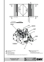
2.7.3.FIXING <strong>AND</strong> CONNECTION OF THE SHAFT SENSORS FOR HYDRAULIC LIFTS<br />
The shaft sensor kit can be of tree different type according to the type of brackets used for<br />
sensors <strong>and</strong> magnets as the following tablet.<br />
The tablet reports also the code of the diagram of the shaft sensor disposition included in<br />
this paragraph.<br />
SENSORS <strong>AND</strong> MAGNETS<br />
A TYPE<br />
KIT BRAKET<br />
B TYPE<br />
KIT BRAKET<br />
C TYPE<br />
KIT BRAKET<br />
Sensors IS, ID, C, D, FCE(optional) CFR CFR G-CFR<br />
Sensors SR, DR, DS CVR SR, DR, DS SR, DR, DS<br />
Magnet bars to comm<strong>and</strong> IS, ID, C, D MFR MFR G-MFR<br />
Round magnet couple to comm<strong>and</strong> SR MVR-SR No Bracket G-MVR-SR<br />
Round magnet couple to comm<strong>and</strong> DR MVR-DR No Bracket G-MVR-DR<br />
Round magnet couple to comm<strong>and</strong> DS MVR-DS No Bracket G-MVR-DS<br />
Diagram for sensor <strong>and</strong> magnet disposition See diagram<br />
CVIA<br />
See diagram<br />
CVIA<br />
See diagram<br />
CVIC<br />
HIGHLIGHT<br />
We recommend that you choose A System or C System for the installation of<br />
magnets. The system ensures tighter fastening of the magnets, a better magnetic<br />
field, less exposure to various bodies (grease, iron fillings….)<br />
With the B System, the magnets without bracket have to be fixed directly on the<br />
guide.<br />
SETRONIK1 Pagina 15 di 54
SEA SYSTEMS<br />
<strong>INSTALLATION</strong> <strong>AND</strong> <strong>USE</strong> <strong>MANUAL</strong><br />
CONTROL PANEL <strong>and</strong> PREWIRED SYSTEM STK1<br />
For Electric <strong>and</strong> Hydraulic Lifts<br />
MSTK12-GB<br />
Rev.01<br />
30/12/05<br />
CVIA<br />
SHAFT SENSORS PLACING FOR HYDRAULIC LIFT WITH A OR B SHAFT SENSOR KIT<br />
HIGHLIGHT<br />
With the B System, the magnets without bracket have to be fixed directly on the<br />
guide.<br />
SHAFT FRONTAL VIEW<br />
CAR ROOF VIEW<br />
SLOWING DISTANCE K<br />
SPEED<br />
K<br />
0.2 m/s 20cm<br />
0.4 m/s 40 cm<br />
0.6 m/s 60 cm<br />
0.8 m/s 80 cm<br />
SETRONIK1 Pagina 16 di 54
SEA SYSTEMS<br />
<strong>INSTALLATION</strong> <strong>AND</strong> <strong>USE</strong> <strong>MANUAL</strong><br />
CONTROL PANEL <strong>and</strong> PREWIRED SYSTEM STK1<br />
For Electric <strong>and</strong> Hydraulic Lifts<br />
MSTK12-GB<br />
Rev.01<br />
30/12/05<br />
CVIC<br />
SHAFT SENSORS PLACING FOR HYDRAULIC LIFT WITH C SHAFT SENSOR KIT<br />
SHAFT FRONTAL VIEW<br />
CAR ROOF VIEW<br />
SLOWING DISTANCE K<br />
SPEED<br />
K<br />
0.2 m/s 20cm<br />
0.4 m/s 40 cm<br />
0.6 m/s 60 cm<br />
0.8 m/s 80 cm<br />
SETRONIK1 Pagina 17 di 54
SEA SYSTEMS<br />
<strong>INSTALLATION</strong> <strong>AND</strong> <strong>USE</strong> <strong>MANUAL</strong><br />
CONTROL PANEL <strong>and</strong> PREWIRED SYSTEM STK1<br />
For Electric <strong>and</strong> Hydraulic Lifts<br />
MSTK12-GB<br />
Rev.01<br />
30/12/05<br />
A) FIXING <strong>AND</strong> CONNECTION OF THE STOP SENSORS AT THE FLOORS:<br />
1. Drive IS <strong>and</strong> ID sensors to the ends of the bracket slots <strong>and</strong> verify that the timer 4.12<br />
is 0000 (no delay);<br />
2. Fix on the car roof the bracket equipped with sensors (CFR) <strong>and</strong> at every floor on<br />
the guide the brackets equipped with magnets (MFR) so that, with the car at the<br />
l<strong>and</strong>ing floor, both sensors <strong>and</strong> magnets are perfectly aligned according to the<br />
diagram CVIA (with A system or B system) or the diagram CVIC (with C system);<br />
3. Connect IS, ID, C, D sensors as per the installation diagrams;<br />
4. Make some calls at the floors, going up <strong>and</strong> down verifying that the car stops with<br />
the floor aligned at the l<strong>and</strong>ing floor.<br />
HIGHLIGHT: Floor Alignment Adjustment<br />
If the stop is advanced, move away the bracket CFR from MFR; if the stop is<br />
delayed, approach the bracket CFR to the MFR.<br />
HIGHLIGHT: Relevelling Zone Adjustment<br />
Should a levelling zone be required, follow the instructions in the Paragraph<br />
2.6.3_Relevelling Zone Adjustment<br />
B) FIXING OF SPEED-CHANGE SENSORS:<br />
1. Fix the speed-change sensors SR, DR, DS on the car roof <strong>and</strong> fix the magnet<br />
couples to the guide so that the sensors <strong>and</strong> the magnets are aligned according to<br />
the diagram CVIA (with A system or B system) or the diagram CVIC (with C system);<br />
2. Connect SR, DS, DR sensors according to the installation diagrams;<br />
3. Adjust the pairs of magnets to match slowing distance K from the l<strong>and</strong>ing as per the<br />
table attached to the diagram CVIA (with A system or B system) or the diagram<br />
CVIC (with C system);<br />
WARNING<br />
To make sure that sensors switch over properly, ascertain that:<br />
- The distance between contiguous magnets on the same axis is major than 5<br />
cm;<br />
- the sensor <strong>and</strong> its corresponding magnet are kept 1÷1.5 cm apart<br />
SETRONIK1 Pagina 18 di 54
SEA SYSTEMS<br />
<strong>INSTALLATION</strong> <strong>AND</strong> <strong>USE</strong> <strong>MANUAL</strong><br />
CONTROL PANEL <strong>and</strong> PREWIRED SYSTEM STK1<br />
For Electric <strong>and</strong> Hydraulic Lifts<br />
MSTK12-GB<br />
Rev.01<br />
30/12/05<br />
C) RELEVELLING ZONE ADJUSTMENT FOR HYDRAULIC LIFTS<br />
HIGHLIGHT: Relevelling Zone<br />
The Relevelling Zone is the space of misalignment between the car <strong>and</strong> the floor<br />
without the car relevels. When the car exceeds this space the relevelling control<br />
starts.<br />
4. Move the sensor IS toward the centre of a length equal to the space of relevelling<br />
zone required.<br />
5. Gradually increase the value of timer 4.12 so that, when upward runs are repeated,<br />
the car stops aligned with the floor sill.<br />
The timer value depends on the required speed <strong>and</strong> Relevelling Zone.<br />
6. Move the sensor ID toward the centre so that, in coming down to the l<strong>and</strong>ing, the car<br />
stops aligned with the sill.<br />
WARNING<br />
The relevelling control with open doors is permitted by the safety circuit (CS1<br />
device <strong>and</strong> C, D sensors).<br />
When the led C <strong>and</strong> D of the CS1 device are on, the relevelling control is<br />
permitted; if one or both of the leds are off the relevelling control with open doors<br />
is interrupted.<br />
SETRONIK1 Pagina 19 di 54
SEA SYSTEMS<br />
<strong>INSTALLATION</strong> <strong>AND</strong> <strong>USE</strong> <strong>MANUAL</strong><br />
CONTROL PANEL <strong>and</strong> PREWIRED SYSTEM STK1<br />
For Electric <strong>and</strong> Hydraulic Lifts<br />
MSTK12-GB<br />
Rev.01<br />
30/12/05<br />
2.7.4. FIXING <strong>AND</strong> CONNECTION OF THE SHAFT SENSORS FOR ELECTRIC LIFTS<br />
The shaft sensor kit can be of two different type according to the type of brackets used for<br />
sensors <strong>and</strong> magnets as the following tablet.<br />
The tablet reports also the code of the diagram of the shaft sensor disposition included in<br />
this paragraph.<br />
SENSORS <strong>AND</strong> MAGNETS<br />
A TYPE<br />
KIT BRAKET<br />
B TYPE<br />
KIT BRAKET<br />
Sensors IS, ID CVF IS, ID<br />
Sensors SR, DR CRF SR, DR<br />
Two round magnet couples for the stop MVF No Bracket<br />
Round magnet couple for speed-change in upward MVR-IS No Bracket<br />
Round magnet couple for speed-change in downward MVR-ID No Bracket<br />
Round magnet couple for speed-change at the upper floor MVR-SR No Bracket<br />
Round magnet couple for speed-change at the lower floor MVR-DR No Bracket<br />
Diagram for sensor <strong>and</strong> magnet disposition <br />
See diagram<br />
CVFA<br />
See diagram<br />
CVFA<br />
HIGHLIGHT<br />
We recommend that you choose A System for the installation of magnets. The<br />
system ensures tighter fastening of the magnets, a better magnetic field, less<br />
exposure to various bodies (grease, iron fillings….)<br />
With the B System, the magnets without bracket have to be fixed directly on the<br />
guide.<br />
SETRONIK1 Pagina 20 di 54
SEA SYSTEMS<br />
<strong>INSTALLATION</strong> <strong>AND</strong> <strong>USE</strong> <strong>MANUAL</strong><br />
CONTROL PANEL <strong>and</strong> PREWIRED SYSTEM STK1<br />
For Electric <strong>and</strong> Hydraulic Lifts<br />
MSTK12-GB<br />
Rev.01<br />
30/12/05<br />
CVFA SHAFT SENSORS PLACING FOR ELECTRIC LIFT WITH A SHAFT SENSOR KIT<br />
HIGHLIGHT<br />
With the B System, the magnets without bracket have to be fixed directly on the<br />
guide.<br />
SLOWING DISTANCE K<br />
SPEED<br />
K<br />
0.6 m/s 60cm<br />
0.8 m/s 80 cm<br />
1 m/s 120 cm<br />
1.2 m/s 140 cm<br />
Zf<br />
Zp<br />
h<br />
Stop Zone (5 cm apart)<br />
Door opening Zone<br />
5 cm apart<br />
SETRONIK1 Pagina 21 di 54
SEA SYSTEMS<br />
<strong>INSTALLATION</strong> <strong>AND</strong> <strong>USE</strong> <strong>MANUAL</strong><br />
CONTROL PANEL <strong>and</strong> PREWIRED SYSTEM STK1<br />
For Electric <strong>and</strong> Hydraulic Lifts<br />
MSTK12-GB<br />
Rev.01<br />
30/12/05<br />
A) FIXING <strong>AND</strong> CONNECTION OF THE STOP SENSORS AT THE FLOORS:<br />
7. Fix on the roof car the IS <strong>and</strong> ID sensors <strong>and</strong> at every floor on the guide the magnet<br />
couples so that, with the car at the l<strong>and</strong>ing floor, both sensors <strong>and</strong> magnets are<br />
perfectly aligned according to the diagram CVIA (with A system or B system) or the<br />
diagram CVIC (with C system);<br />
8. Connect IS, ID sensors as per the installation diagrams;<br />
9. Adjust the pairs of magnets so that, going up <strong>and</strong> down, the car stops with the floor<br />
aligned at the l<strong>and</strong>ing floor.<br />
B) FIXING OF SPEED-CHANGE SENSORS:<br />
10. Fix next at every floor on the guide the round magnet couples, so that they are<br />
aligned to the sensors IS <strong>and</strong> ID according to the diagram CVFA;<br />
11. Fix on the car roof the sensors SR <strong>and</strong> DR <strong>and</strong> next to the upper floor <strong>and</strong> the lower<br />
floor on the guide the round magnets so that the sensors <strong>and</strong> magnets are aligned<br />
as specified in the layout L02;<br />
12. Connect SR, DR sensors according to the installation diagrams;<br />
13. Adjust the pairs of magnets to match slowing distance K from the l<strong>and</strong>ing as per the<br />
table attached to diagram CVFA.<br />
WARNING<br />
To make sure that sensors switch over properly, ascertain that:<br />
• The distance between contiguous magnets on the same axis is major than 5<br />
cm;<br />
• the sensor <strong>and</strong> its corresponding magnet are kept 1÷1.5 cm apart<br />
SETRONIK1 Pagina 22 di 54
SEA SYSTEMS<br />
<strong>INSTALLATION</strong> <strong>AND</strong> <strong>USE</strong> <strong>MANUAL</strong><br />
CONTROL PANEL <strong>and</strong> PREWIRED SYSTEM STK1<br />
For Electric <strong>and</strong> Hydraulic Lifts<br />
MSTK12-GB<br />
Rev.01<br />
30/12/05<br />
2.8.INSULATION TEST<br />
Before carrying out the flash tests reported in the following table, perform the following<br />
operations:<br />
1 Bring the car out of the l<strong>and</strong>ing zone;<br />
2 De-energise QM master switch <strong>and</strong> QF light switch;<br />
3 Pull out <strong>and</strong> insulate the ground cables that reach the panel;<br />
4 Unplug the phone line from the dialling key.<br />
FROM<br />
TO<br />
GROUND<br />
_____<br />
___<br />
_<br />
Master Switch,<br />
Motors<br />
R,S,T, U,V,W,<br />
U1,V1,W1<br />
U2,V2,W2<br />
Safety dev.,<br />
Brake,<br />
Retractable<br />
Sliding block<br />
1..10, F+,F-,<br />
PR+,PR-<br />
Master<br />
Switch,<br />
Motors<br />
R,S,T,<br />
U,V,W,<br />
U1,V1,W1<br />
U2,V2,W2<br />
Safety dev.,<br />
Brake,<br />
Retractable<br />
Sliding<br />
block<br />
1..10, F+,F-,<br />
PR+,PR-<br />
Three-phase<br />
Motor, Doors<br />
MP,MP,MP,<br />
MP1,MP1,MP1<br />
Car<br />
Lighting<br />
L1,L,N<br />
d.c. Motor,<br />
Doors<br />
+,-,30,32,<br />
MP,MP<br />
Signals<br />
OCC,FD,FS,<br />
PS1,PS2…<br />
<br />
NO <br />
NO NO <br />
Alarm<br />
<br />
AL+, AL-, AL NO NO <br />
Car Lighting<br />
<br />
L1,L,N NO <br />
Signals<br />
OCC,FD,FS,PS1<br />
NO<br />
Safety Circuit<br />
<br />
DI,XC2,CI,XC1 NO NO <br />
= Insulation test to be carried out.<br />
SETRONIK1 Pagina 23 di 54
SEA SYSTEMS<br />
<strong>INSTALLATION</strong> <strong>AND</strong> <strong>USE</strong> <strong>MANUAL</strong><br />
CONTROL PANEL <strong>and</strong> PREWIRED SYSTEM STK1<br />
For Electric <strong>and</strong> Hydraulic Lifts<br />
MSTK12-GB<br />
Rev.01<br />
30/12/05<br />
2.9.SYSTEM COMMISSIONING<br />
1. Make sure that the maintenance push-button panel switch placed on the car roof is set<br />
to NORMAL;<br />
2. Turn ON the control panel <strong>and</strong> ascertain that the following leds are switched ON:<br />
1, 2, 8, 10, CM, 01, +5 (in case of Hydraulic lift also TC <strong>and</strong> PST);<br />
3. Should any problems arise (ex: alarmed card: ALL leds ON), refer to Paragraph 6:<br />
Basic Troubleshooting Procedures.<br />
SETRONIK1 Pagina 24 di 54
SEA SYSTEMS<br />
<strong>INSTALLATION</strong> <strong>AND</strong> <strong>USE</strong> <strong>MANUAL</strong><br />
CONTROL PANEL <strong>and</strong> PREWIRED SYSTEM STK1<br />
For Electric <strong>and</strong> Hydraulic Lifts<br />
MSTK12-GB<br />
Rev.01<br />
30/12/05<br />
3.PROGRAMMING<br />
3.1PROGRAMMER CONNECTION (STK2-PM)<br />
ab<br />
1. Check that the ON\OFF switch of the Keyboard is in the OFF position.<br />
2. Insert the connection cable in connector FC3 on the STK1-B board.<br />
3. Bring the ON\OFF switch in the ON position.<br />
4. All the 7 displays show the number 8 for about 2”: this function is used to check that<br />
all displays are working correctly.<br />
5. After the 2”, the displays show 0.00.XXXX (X indicates any number), or 0.00.0000<br />
with the last four digits flashing. In this second case it means that an access code<br />
has been stored <strong>and</strong> that it is therefore necessary to enter the digits of the access<br />
code in the last 4 displays (DG3..DG6) <strong>and</strong> then to press .<br />
d e f<br />
g c<br />
a= Displays indicating the Parameter Code, marked as DG0, DG1 <strong>and</strong> DG2.<br />
b= Displays indicating the Parameter Value, marked DG3, DG4, DG5, DG6.<br />
c= DIN guide release<br />
d= ON\OFF switch.<br />
e= Connection cable to connector FC3 on the STK1-B board.<br />
f= Pushbutton to select the display from DG0 to DG6, scrolling from left to right<br />
whenever it is pressed. The selected display flashes.<br />
g= Pushbuttons , to modify the number of the display previously selected.<br />
(Please refer to ‘Example of programmer use’ Par. 3.2)<br />
SETRONIK1 Pagina 25 di 54
SEA SYSTEMS<br />
<strong>INSTALLATION</strong> <strong>AND</strong> <strong>USE</strong> <strong>MANUAL</strong><br />
CONTROL PANEL <strong>and</strong> PREWIRED SYSTEM STK1<br />
For Electric <strong>and</strong> Hydraulic Lifts<br />
MSTK12-GB<br />
Rev.01<br />
30/12/05<br />
3.2.EXAMPLE OF PROGRAMMER <strong>USE</strong><br />
The example below shows how it is possible to set the timer for the parking time on the<br />
l<strong>and</strong>ing (or of occupied). (Please refer also to paragraph ‘Timers Programming’)<br />
1. Set Parameter Code 4.02 on displays DG0,DG1,DG2:<br />
1.1. Select DG0, by pressing pushbutton until DG0 flashes:<br />
DG0 DG1 DG2 DG3 DG4 DG5 DG6<br />
DG0 flashes<br />
1.2. Set 4 on DG0 using pushbuttons , :<br />
DG0 DG1 DG2 DG3 DG4 DG5 DG6<br />
4<br />
DG0 flashes<br />
1.3. Select DG1 <strong>and</strong> DG2, by pressing the pushbutton once<br />
(DG1 <strong>and</strong> DG2 flash):<br />
DG0 DG1 DG2 DG3 DG4 DG5 DG6<br />
4<br />
DG1<strong>and</strong> DG2 flash<br />
1.4. Set 2 on DG1,DG2 by pushbutton:<br />
DG0 DG1 DG2 DG3 DG4 DG5 DG6<br />
4 0 2<br />
DG1 <strong>and</strong> DG2 flash<br />
2. Set the timer time on displays DG3..DG6:<br />
2.1. Select displays DG3, DG4, DG5, DG6 by pressing the pushbutton once<br />
DG0 DG1 DG2 DG3 DG4 DG5 DG6<br />
4 0 2<br />
DG3..DG6 flash<br />
2.2. Set the time (i.e. 8 seconds = 80 tenths of a second) by pushbutton<br />
DG0 DG1 DG2 DG3 DG4 DG5 DG6<br />
4 0 2 0 0 8 0<br />
DG3..DG6 flash<br />
NOTA<br />
The value set is operational by pressing once, but it is not stored.<br />
For the storing please refer to paragraph 3.4_Parameters Storing..<br />
SETRONIK1 Pagina 26 di 54
SEA SYSTEMS<br />
<strong>INSTALLATION</strong> <strong>AND</strong> <strong>USE</strong> <strong>MANUAL</strong><br />
CONTROL PANEL <strong>and</strong> PREWIRED SYSTEM STK1<br />
For Electric <strong>and</strong> Hydraulic Lifts<br />
MSTK12-GB<br />
Rev.01<br />
30/12/05<br />
3.3.PROGRAMMING THE CUSTOMER SECRET ACCESS CODE.<br />
1. Set Parameter Code 0.10 on displays DG0,DG1,DG2 .<br />
DG0 DG1 DG2 DG3 DG4 DG5 DG6<br />
0 1 0<br />
ACCESS CODE<br />
The old access code stored is displayed. If no code has been entered, value 0000 is<br />
displayed.<br />
Enter the new access code on displays DG3..DG6.<br />
(Value 0000 removes the access code)<br />
2. Set Parameter Code 0.11 on displays DG0, DG1, DG2.<br />
DG0 DG1 DG2 DG3 DG4 DG5 DG6<br />
0 1 1<br />
ACCESS CODE<br />
Enter the same access code entered in point 2 on displays DG3..DG6. If the code is<br />
different, the same is not accepted, therefore the old code previously stored, if any, is<br />
valid.<br />
(Value 0000 removes the access code)<br />
3. Perform the storing. (Please refer to the Par.3.4_Parameters Storing).<br />
SETRONIK1 Pagina 27 di 54
SEA SYSTEMS<br />
<strong>INSTALLATION</strong> <strong>AND</strong> <strong>USE</strong> <strong>MANUAL</strong><br />
CONTROL PANEL <strong>and</strong> PREWIRED SYSTEM STK1<br />
For Electric <strong>and</strong> Hydraulic Lifts<br />
MSTK12-GB<br />
Rev.01<br />
30/12/05<br />
3.4.PARAMETERS STORING.<br />
This parameter execute the comm<strong>and</strong> for the permanent storing of the parameters<br />
modified. If this operation is not performed, any modifications made remain valid until the<br />
power supply to the STK1_B boards is cut off.<br />
1. Set Parameter Code 0.12 on displays DG0, DG1, DG2.<br />
DG0 DG1 DG2 DG3 DG4 DG5 DG6<br />
0 1 2 0 0 0 0<br />
2. Press : DG3..DG6 flash.<br />
DG0 DG1 DG2 DG3 DG4 DG5 DG6<br />
0 1 2 0 0 0 0<br />
3. Press for one second, then displays DG3..DG6 indicate the following result of the<br />
operation:<br />
DG0 DG1 DG2 DG3 DG4 DG5 DG6<br />
0 1 2 0 0 0 2<br />
STORING HAS CORRECTLY<br />
TAKEN PLACE<br />
Or<br />
DG0 DG1 DG2 DG3 DG4 DG5 DG6<br />
0 1 2 0 0 0 3<br />
STORING INCORRECT.<br />
Repeat the comm<strong>and</strong> or replace the board.<br />
SETRONIK1 Pagina 28 di 54
SEA SYSTEMS<br />
<strong>INSTALLATION</strong> <strong>AND</strong> <strong>USE</strong> <strong>MANUAL</strong><br />
CONTROL PANEL <strong>and</strong> PREWIRED SYSTEM STK1<br />
For Electric <strong>and</strong> Hydraulic Lifts<br />
MSTK12-GB<br />
Rev.01<br />
30/12/05<br />
3.5.PROGRAMMING THE LIFT, OPERATION, SELECTOR.<br />
In order to be able to modify the parameter values, it is necessary to disconnect the FA<br />
automatic valve while, to only display the same, this is not necessary.<br />
DG0 DG1 DG2 DG3 DG4 DG5 DG6<br />
1 0 0<br />
MASTER / SLAVE<br />
0= Single Lift<br />
1= Master control panel for Duplo with two signalings<br />
‘Coming’<br />
2= Master control panel for Duplo with one signaling<br />
‘Coming’<br />
3= Slave control panel for Duplo<br />
4= Not used<br />
SELECTOR TYPE<br />
0= Shaft with magnetic switches without safety circuit<br />
(CS1)<br />
1= Shaft with magnetic switches with safety circuit<br />
(CS1)<br />
OPERATION TYPE<br />
0= APB<br />
1= Not enabled<br />
2= Down collective<br />
3= Up <strong>and</strong> down Collective<br />
4= Pick-Up<br />
LIFT TYPE<br />
0= 1 speed Electric lift<br />
1= 2 speed Electric lift<br />
2= 2 speed Electric lift with ACVV<br />
3= Electric lift for Inverter without encoder<br />
4= Electric lift for Inverter with encoder<br />
5= Hydraulic lift<br />
DG0 DG1 DG2 DG3 DG4 DG5 DG6<br />
1 0 1<br />
NUMBER OF SERVICES<br />
NUMBER OF STOPS<br />
SETRONIK1 Pagina 29 di 54
SEA SYSTEMS<br />
<strong>INSTALLATION</strong> <strong>AND</strong> <strong>USE</strong> <strong>MANUAL</strong><br />
CONTROL PANEL <strong>and</strong> PREWIRED SYSTEM STK1<br />
For Electric <strong>and</strong> Hydraulic Lifts<br />
MSTK12-GB<br />
Rev.01<br />
30/12/05<br />
3.6.PROGRAMMING THE MAIN FLOOR, PARKING FLOOR, PREFERENTIAL FLOOR,<br />
FIREMEN <strong>AND</strong> FIRE-FIGHTING FLOOR, DUPLO VERTICAL RISE FLOORS<br />
DG0 DG1 DG2 DG3 DG4 DG5 DG6<br />
1 0 2<br />
- PARKING FLOOR (TIMER 4.08)<br />
- PREFERENTIAL OPERATION FLOOR<br />
MAIN FLOOR<br />
DG0 DG1 DG2 DG3 DG4 DG5 DG6<br />
1 0 3<br />
FIREMAN FLOOR #2<br />
(Input Function 9)<br />
FIREMAN FLOOR #1<br />
(Input Function 8 o 22)<br />
DG0 DG1 DG2 DG3 DG4 DG5 DG6<br />
1 0 4<br />
NUMBER OF DUPLO VERTICAL RISE FLOORS<br />
(to be programmed on the panel of the lower lift)<br />
NOTA<br />
Floors numbering starts from number 1 corresponding to the lower external floor<br />
SETRONIK1 Pagina 30 di 54
SEA SYSTEMS<br />
<strong>INSTALLATION</strong> <strong>AND</strong> <strong>USE</strong> <strong>MANUAL</strong><br />
CONTROL PANEL <strong>and</strong> PREWIRED SYSTEM STK1<br />
For Electric <strong>and</strong> Hydraulic Lifts<br />
MSTK12-GB<br />
Rev.01<br />
30/12/05<br />
3.7.PROGRAMMING THE OPERATOR<br />
DG0 DG1 DG2 DG3 DG4 DG5 DG6<br />
1 0 5<br />
OPERATOR A:<br />
OPERATOR B<br />
See Operator A<br />
Floor Doors Car Doors Limit switches Notes<br />
00 No Available No Available No Available<br />
01 Manual Manual Nothing<br />
02 Manual safety photocell Nothing<br />
03 Manual Automatic Closing <strong>and</strong> Opening (1)<br />
04 Manual Automatic Opening (1)<br />
05 Manual Automatic Nothing (2)<br />
09 Automatic Automatic Closing <strong>and</strong> Opening (1), (4)<br />
10 Automatic Automatic Closing <strong>and</strong> Opening (1)<br />
11 Automatic Automatic Opening (1)<br />
12 Automatic Automatic Nothing (2)<br />
13 Automatic Automatic Nothing (2), (3)<br />
(1) = Set the timer 4.04 (for Operator A) end/or the timer 4.05 (for operator B) twice the<br />
door closing time;<br />
(Limit switches are controlled: see error codes from 76 to 79)<br />
(2) Set the timer 4.04 (for Operator A) end/or the timer 4.05 (for operator B) equal to the<br />
door closing time;<br />
(3) = The door opening/closing signal is turned off when the set with the timer 4.04<br />
end/or 4.05 is over;<br />
(4) = Set the timer 4.06 (for both operators A <strong>and</strong> B) to delay the door ri-opening after<br />
the photocell activation (with 4.06.0000 = immediate ri-opening)<br />
Operators with Motor power supplied during the run with closing limit switch:<br />
In case of operators that need to be power supplied during le lift run, it is necessary to use<br />
the input programmable functions 30 <strong>and</strong> 31 (see par. 3.14)<br />
SETRONIK1 Pagina 31 di 54
SEA SYSTEMS<br />
<strong>INSTALLATION</strong> <strong>AND</strong> <strong>USE</strong> <strong>MANUAL</strong><br />
CONTROL PANEL <strong>and</strong> PREWIRED SYSTEM STK1<br />
For Electric <strong>and</strong> Hydraulic Lifts<br />
MSTK12-GB<br />
Rev.01<br />
30/12/05<br />
3.8.PROGRAMMING MAX FLOOR RE-LEVELLINGS, POSITION INDICATIONS.<br />
DG0 DG1 DG2 DG3 DG4 DG5 DG6<br />
1 0 6<br />
TYPE OF POSITION INDICATIONS<br />
00= Positional (one output for each position)<br />
01= Denied BDC display (Relative to Main Floor)<br />
02= Absolute Gray code display<br />
03= Relative Gray Code display (Relative to Main<br />
Floor)<br />
04= Binary Code display<br />
MAX. NUMBER OF FLOOR RE-LEVELLINGS<br />
Once the lift has reached the value set, the lift goes<br />
out of service (Only for hydraulic lifts)<br />
If set on 00, this function is not considered.<br />
SETRONIK1 Pagina 32 di 54
SEA SYSTEMS<br />
<strong>INSTALLATION</strong> <strong>AND</strong> <strong>USE</strong> <strong>MANUAL</strong><br />
CONTROL PANEL <strong>and</strong> PREWIRED SYSTEM STK1<br />
For Electric <strong>and</strong> Hydraulic Lifts<br />
MSTK12-GB<br />
Rev.01<br />
30/12/05<br />
3.9.PROGRAMMING OF SPEED <strong>AND</strong> STOP MODE DURING INSPECTION, MOVABLE<br />
PLATFORM, ADVANCE DOORS OPENING, RE-LEVELLING, GONG<br />
DG0 DG1 DG2 DG3 DG4 DG5 DG6<br />
1 0 7<br />
GONG ACTIVATION<br />
0= Upon speed change only for external calls<br />
1= On floor only for external calls<br />
2= Upon speed change for internal or external calls<br />
3= On floor for internal or external calls<br />
ADVANCE DOORS OPENING <strong>AND</strong> FLOOR LEVELLINGS<br />
0= No function enabled<br />
1= Advance door opening enabled during run, safety<br />
circuit required (CS1)<br />
2= Floor levelling enabled, safety circuit required<br />
(CS1)<br />
3= Advance doors opening <strong>and</strong> floor levelling, safety<br />
circuit required (CS1).<br />
MOVABLE PLATFORM (*)<br />
0= NA contact, in APB operation when closed it<br />
disables external calls<br />
1= NA contact, in APB operation <strong>and</strong> upon call when<br />
closed it enables internal calls<br />
2= NC contact, in APB operation when open it<br />
disables external calls<br />
3= NC contact, in APB operation <strong>and</strong> upon call when<br />
open it enables internal calls<br />
SPEED <strong>AND</strong> STOP MODE DURING MAINTENANCE<br />
0= Low speed, stop on resetters<br />
1= High speed, stop on resetters<br />
2= High speed, stop on pre-limit switches<br />
3= Low speed, stop on pre-limit-switches<br />
(*) MOVABLE PLATFORM= If there isn’t the movable platform, program to 0<br />
SETRONIK1 Pagina 33 di 54
SEA SYSTEMS<br />
<strong>INSTALLATION</strong> <strong>AND</strong> <strong>USE</strong> <strong>MANUAL</strong><br />
CONTROL PANEL <strong>and</strong> PREWIRED SYSTEM STK1<br />
For Electric <strong>and</strong> Hydraulic Lifts<br />
MSTK12-GB<br />
Rev.01<br />
30/12/05<br />
3.10.PROGRAMMING OF OVERLOAD CONTACT<br />
DG0 DG1 DG2 DG3 DG4 DG5 DG6<br />
1 0 8<br />
OVERLOAD CONTACT (INPUT CE)<br />
0=Contact NO;<br />
1=Contact NC<br />
SETRONIK1 Pagina 34 di 54
SEA SYSTEMS<br />
<strong>INSTALLATION</strong> <strong>AND</strong> <strong>USE</strong> <strong>MANUAL</strong><br />
CONTROL PANEL <strong>and</strong> PREWIRED SYSTEM STK1<br />
For Electric <strong>and</strong> Hydraulic Lifts<br />
MSTK12-GB<br />
Rev.01<br />
30/12/05<br />
3.11.PROGRAMMING OF SERVICES.<br />
In order to modify the parameters values, it is necessary to disconnect the FA automatic<br />
valve while, to only display the same, this is not necessary.<br />
DG0 DG1 DG2 DG3 DG4 DG5 DG6<br />
2<br />
TYPE OF OPENING <strong>AND</strong><br />
DOOR STATUS IN PARKING FOR B ACCESS:<br />
See Type of Opening <strong>and</strong> Door status in parking for A<br />
Access<br />
B ACCESS TYPE:<br />
See A access Type<br />
TYPE OF OPENING <strong>AND</strong><br />
DOOR STATUS IN PARKING FOR A ACCESS:<br />
0= Selective, doors open parking<br />
1= Simultaneous, doors open parking<br />
2= Selective, doors closed parking<br />
3= Simultaneous, doors closed parking<br />
A ACCESS TYPE:<br />
0= There is no service<br />
1= Simplex Access (*)<br />
2= Duplo Access (*)<br />
STOP<br />
01= Stop1<br />
02= Stop2<br />
03= Stop3<br />
04= Stop4<br />
.<br />
.<br />
.<br />
12= Stop12<br />
(*) Simplex / Duplo Access= The Access has to be programmed Simplex if the relative<br />
stop is served by only one lift (in this case the Simplex access has to be<br />
programmed on this lift);<br />
The access has to be programmed Duplo if the relative stop is served by both the<br />
lifts (in this case the Duplo Access has to be programmed on both the lifts).<br />
SETRONIK1 Pagina 35 di 54
SEA SYSTEMS<br />
<strong>INSTALLATION</strong> <strong>AND</strong> <strong>USE</strong> <strong>MANUAL</strong><br />
CONTROL PANEL <strong>and</strong> PREWIRED SYSTEM STK1<br />
For Electric <strong>and</strong> Hydraulic Lifts<br />
MSTK12-GB<br />
Rev.01<br />
30/12/05<br />
3.12.SHAFT PROGRAMMING:<br />
In order to modify the parameters values, it is necessary to disconnect the FA automatic<br />
valve while, to only display the same, this is not necessary.<br />
DG0 DG1 DG2 DG3 DG4 DG5 DG6<br />
3 00<br />
INTER-FLOOR TYPE (*)<br />
00= Normal Floors<br />
(Interfloor > 2K)<br />
01= Short Floors<br />
(Interfloor < 2K <strong>and</strong> > 1K)<br />
02= Close Floors<br />
(Interfloor < 1K <strong>and</strong> > 2 brackets)<br />
03= Very Close Floors<br />
(Interfloor < 2 brackets: a second bracket is<br />
required)<br />
INTER-FLOOR SELECTION<br />
01= Inter-floor between floor 1 <strong>and</strong> 2<br />
02= Inter-floor between floor 2 <strong>and</strong> 3<br />
03= Inter-floor between floor 3 <strong>and</strong> 4<br />
04= Inter-floor between floor 4 <strong>and</strong> 5<br />
05= Inter-floor between floor 5 <strong>and</strong> 6<br />
06= Inter-floor between floor 6 <strong>and</strong> 7<br />
07= Inter-floor between floor 7 <strong>and</strong> 8<br />
08= Inter-floor between floor 8 <strong>and</strong> 9<br />
09= Inter-floor between floor 9 <strong>and</strong> 10<br />
10= Inter-floor between floor 10 <strong>and</strong> 11<br />
11= Inter-floor between floor 11 <strong>and</strong> 12<br />
(*) = K is the slowing distance: see the layout L01 <strong>and</strong> L02.<br />
SETRONIK1 Pagina 36 di 54
SEA SYSTEMS<br />
<strong>INSTALLATION</strong> <strong>AND</strong> <strong>USE</strong> <strong>MANUAL</strong><br />
CONTROL PANEL <strong>and</strong> PREWIRED SYSTEM STK1<br />
For Electric <strong>and</strong> Hydraulic Lifts<br />
MSTK12-GB<br />
Rev.01<br />
30/12/05<br />
3.13.PROGRAMMING OF TIMERS:<br />
DG0 DG1 DG2 DG3 DG4 DG5 DG6<br />
4<br />
TIME<br />
Expressed in tenths of a second<br />
(i.e. 0080 = 8 seconds)<br />
TIMER<br />
00= Max duration of the inter-floor run<br />
01= Max duration run in low speed (if 4.01=0000 the timer is not enabled)<br />
02= Floor parking duration (occupied)<br />
03= Floor parking reduced duration after photocell activation<br />
04= Max duration of the stage side A lift doors opening/closing<br />
(See error codes from 76 to 77)<br />
05= Max duration of the stage side B lift doors opening/closing<br />
(See error codes from 78 to 79)<br />
06= doors opening delay after stop or door re-opening delay with operator 09<br />
07= Max time at start (after the drop out of closing / opening contactors)<br />
08= despatch delay to parking floor<br />
(if 4.08=0000 the timer is not enabled)<br />
09= despatch delay to lower outmost floor (for hydraulic lifts)<br />
(if 4.09=0000 the timer is not enabled)<br />
10= combinable with output functions to be programmed<br />
11= combinable with output functions to be programmed<br />
12= Stop delay to adjust the relevelling space<br />
(see paragraph 2.6.3_‘Relevelling space adjustment’)<br />
13= Max time of the call holding with still car<br />
14= contactors excitation delay at start (this is used to avoid false excitations of operating<br />
contactors due to safety contacts bouncing)<br />
15= doors opening delay due to the activation of the safety circuit (used with door opening<br />
in advance)<br />
SETRONIK1 Pagina 37 di 54
SEA SYSTEMS<br />
<strong>INSTALLATION</strong> <strong>AND</strong> <strong>USE</strong> <strong>MANUAL</strong><br />
CONTROL PANEL <strong>and</strong> PREWIRED SYSTEM STK1<br />
For Electric <strong>and</strong> Hydraulic Lifts<br />
MSTK12-GB<br />
Rev.01<br />
30/12/05<br />
3.14.INPUT PROGRAMMING:<br />
DG0 DG1 DG2 DG3 DG4 DG5 DG6<br />
5 00<br />
INPUT FUNCTION<br />
00 None<br />
INPUTS: 01 - Safety photocells (With operators in 02 type);<br />
- Door opening extralimit switch of the 1° <strong>and</strong> 2° operator (with<br />
operator different from 02 type) (NC contact)<br />
Led Term. 02 Oil thermal sensor (NC contact)<br />
00 03 Low point pressure switch (NC contact)<br />
01 X1 X1 04 Peak point pressure switch (NC contact)<br />
02 (*) X2 X2 05 L<strong>and</strong>ing operation stop control (for ACVV or 3VF with old interface)<br />
03 (*) X3 X3 06 Operator A sticking contactor control<br />
04 (*) X4 X4 07 Operator B sticking contactor control<br />
05 (*) X5 X5 08 Fire-fighting operation with despatch to the fire-fighting floor #1<br />
06 X6 J8.4 09 Fire-fighting operation with despatch to the fire-fighting floor #2<br />
07 (*) X7 J9.4 10 Preferential operation<br />
08 X8 J2.4 11 Safety circuit control (err 19, 20)<br />
09 X9 J2.5 12 Very close l<strong>and</strong>ings control (with Additional ID switch)<br />
10 X10 J2.6 13 Very close l<strong>and</strong>ings control (with Additional IS switch)<br />
11 X11 J2.7 14 High/low speed Maintenance<br />
12 FG FG 16 Full load<br />
13 MR MR 17 Alarm with 0094 error, Out-of-service on l<strong>and</strong>ing<br />
14 TC TC 18 Additional extralimit switch in the top_Contact monitoring <strong>and</strong> 0095<br />
error signalling<br />
15 PST PST 19 Alarm with 0096 error, immediate out-of-service<br />
16 MP MP 20 Alarm with 0097 error, Failed start (3VF)<br />
21 Reserved operation<br />
22 Hong Kong Firemen operation<br />
23 Photocell of the operator A independent of the opening push button<br />
(*) = Leds <strong>and</strong><br />
terminals are on the<br />
expansion card<br />
STK1-E<br />
(used with selective opening)<br />
24 Photocell of the operator B independent of the opening push button<br />
(used with selective opening)<br />
25 Out-of-service with despatch to the programmed parking floor with<br />
signalling of error 098<br />
26 BA1 input (NA) for panels without board STK1-E<br />
28 Emergency operation (not with board B12E)<br />
29 CM1 input (NC) for panels without board STK1-E<br />
30 Doors closing limit switch for operator A (NC contact for lifts with<br />
motors powered during the run)<br />
31 Doors closing limit switch for operator B (NC contact for lifts with<br />
motors powered during the run)<br />
32 Low <strong>and</strong> peak point pressure switch (PST) (NC contact; it can be<br />
used only on inputs X6, X9, FG, PST)<br />
NOTE: If it isn’t specified the contacts are N.O.<br />
SETRONIK1 Pagina 38 di 54
SEA SYSTEMS<br />
<strong>INSTALLATION</strong> <strong>AND</strong> <strong>USE</strong> <strong>MANUAL</strong><br />
CONTROL PANEL <strong>and</strong> PREWIRED SYSTEM STK1<br />
For Electric <strong>and</strong> Hydraulic Lifts<br />
MSTK12-GB<br />
Rev.01<br />
30/12/05<br />
3.15.OUTPUT PROGRAMMING:<br />
DG0 DG1 DG2 DG3 DG4 DG5 DG6<br />
5 00<br />
OUTPUT FUNCTION<br />
Timer<br />
00 None<br />
01 Door opening comm<strong>and</strong> for operator A (NO) 4.04<br />
Led Term. 02 Door opening comm<strong>and</strong> for operator B (NO) 4.05<br />
17 01 32 / J8.2 03 Door closing comm<strong>and</strong> for operator A (NO) 4.04<br />
18 02 30 / J8.3 04 Door closing comm<strong>and</strong> for operator B (NO) 4.05<br />
19 (*) 03 42 / J9.2 05 Fixed occupied comm<strong>and</strong>, car light<br />
20 (*) 04 40 / J9.3 06 Retiring cam comm<strong>and</strong><br />
21 05 J7.1 / J7.2 07 Stop comm<strong>and</strong> at stop: for ACVV e 3VF with old interface<br />
22 06 J7.1 / J7.3 08 Soft Starter comm<strong>and</strong><br />
09 Soft Stop comm<strong>and</strong> during upward run 4.10<br />
10 Delta contactor comm<strong>and</strong> 4.11<br />
(*) = Leds <strong>and</strong> terminals 12 Soft Stop comm<strong>and</strong> during upward <strong>and</strong> downward run 4.10<br />
are on the expansion 13 Brake comm<strong>and</strong> with 3VF starting 4.11<br />
card STK1-E<br />
14 Resistors or impedance exclusion comm<strong>and</strong> (SCC) at 4.11<br />
start<br />
15 Resistors exclusion comm<strong>and</strong> upon speed change 4.10<br />
16 CS1 enabling (obsolete)<br />
17 Intermediate speed comm<strong>and</strong> between short floors with<br />
3VF (obsolete)<br />
18 Intermediate speed comm<strong>and</strong> between close floors with<br />
3VF (obsolete)<br />
19 Relevelling comm<strong>and</strong><br />
20 Relay KV1 comm<strong>and</strong> for 3VF<br />
21 Relay KV2 comm<strong>and</strong> for 3VF<br />
22 Door closing comm<strong>and</strong> for both the operators<br />
23 Door opening comm<strong>and</strong> for operator A (NC) 4.04<br />
24 Door opening comm<strong>and</strong> for operator B (NC) 4.05<br />
25 VMP comm<strong>and</strong> with Soft Stop <strong>and</strong> valve 2CH 4.11<br />
26 Alarm filtering comm<strong>and</strong><br />
NOTE: Functions 0016, 0017, 0018 are obsolete with diagrams based on Eprom 4.00 or<br />
later types.<br />
SETRONIK1 Pagina 39 di 54
SEA SYSTEMS<br />
<strong>INSTALLATION</strong> <strong>AND</strong> <strong>USE</strong> <strong>MANUAL</strong><br />
CONTROL PANEL <strong>and</strong> PREWIRED SYSTEM STK1<br />
For Electric <strong>and</strong> Hydraulic Lifts<br />
MSTK12-GB<br />
Rev.01<br />
30/12/05<br />
4.DIAGNOSIS<br />
4.1.LIFT STATUS DISPLAY<br />
The parameter value (DG3..DG6) is constantly updated in relation to the current status of<br />
the lift.<br />
If the Car Position is 00 (DG5, DG6), this means that the resetting operation has not been<br />
performed.<br />
DG0 DG1 DG2 DG3 DG4 DG5 DG6<br />
0 0 0<br />
CAR POSITION<br />
0= Lift without resetting<br />
n= Actual position ( from 1 to 12)<br />
OPERATION STATUS<br />
0= Floor parking<br />
1= Doors closing for start<br />
2= High speed motion<br />
3= Low speed motion<br />
4= Doors opening<br />
5= Car still off l<strong>and</strong>ing<br />
LIFT STATUS<br />
0= Normal operation<br />
1= Firemen operation on<br />
2= Fire-fighting operation on<br />
3= Preferential operation on<br />
4= Reserved operation on<br />
5= Safety photocell action<br />
6= Not used<br />
7= Out-of-service for failures at floor<br />
8= Out-of-service for permanent failures<br />
9= Maintenance operation on<br />
SETRONIK1 Pagina 40 di 54
SEA SYSTEMS<br />
<strong>INSTALLATION</strong> <strong>AND</strong> <strong>USE</strong> <strong>MANUAL</strong><br />
CONTROL PANEL <strong>and</strong> PREWIRED SYSTEM STK1<br />
For Electric <strong>and</strong> Hydraulic Lifts<br />
MSTK12-GB<br />
Rev.01<br />
30/12/05<br />
4.2.DISPLAY <strong>AND</strong> CANCELLATION OF FAILURES / MALFUNCTIONS<br />
A).DISPLAY OF THE LAST FAILURE:<br />
Set ‘Parameter Code’ 001 on displays DG0, DG1, DG2:<br />
DG0 DG1 DG2 DG3 DG4 DG5 DG6<br />
0 0 1<br />
FAILURE CODE<br />
NUMBER OF TIMES THE BOARD DETECTED THE FAILURE<br />
(MAX 9)<br />
If the parameter value (DG3..DG6) is 0000, this means that no failure or malfunction has<br />
occurred.<br />
B).DISPLAY OF THE LAST 16 FAILURES:<br />
Set ‘Parameter Code’ 0.02 on displays DG0, DG1, DG2 <strong>and</strong> press :<br />
DG0 DG1 DG2 DG3 DG4 DG5 DG6<br />
0 0 2<br />
DG3.. DG6 FLASH<br />
FAILURE CODE<br />
NUMBER OF TIMES THE BOARD HAS DETECTED THE<br />
FAILURE (MAX 9)<br />
By pressing pushbutton<br />
By pressing pushbutton<br />
it is possible to display subsequent failures.<br />
it is possible to display previous failures.<br />
If the parameter value (DG3..DG6) is 0000, this means that no failure/malfunction has<br />
occurred or the end of the failure codes list has been reached.<br />
C).FAILURES CANCELLATION:<br />
1. Set ‘Parameter Code’ 0.03 on displays DG0, DG1, DG2 <strong>and</strong> press :<br />
DG0 DG1 DG2 DG3 DG4 DG5 DG6<br />
0 0 3 0 0 0 0<br />
DG3..DG6 FLASH<br />
2. Press . The parameter value (DG3..DG6) shows 0001 to indicate that failures have<br />
been deleted:<br />
DG0 DG1 DG2 DG3 DG4 DG5 DG6<br />
0 0 3 0 0 0 1<br />
FAILURES DELETED<br />
SETRONIK1 Pagina 41 di 54
SEA SYSTEMS<br />
<strong>INSTALLATION</strong> <strong>AND</strong> <strong>USE</strong> <strong>MANUAL</strong><br />
CONTROL PANEL <strong>and</strong> PREWIRED SYSTEM STK1<br />
For Electric <strong>and</strong> Hydraulic Lifts<br />
MSTK12-GB<br />
Rev.01<br />
30/12/05<br />
4.3.COUNT OF RUNS <strong>AND</strong> RE-LEVELLINGS PERFORMED.<br />
A).UP <strong>AND</strong> DOWN RUNS COUNT<br />
DG0 DG1 DG2 DG3 DG4 DG5 DG6<br />
0 0 0<br />
NUMBER OF TENS OF RUNS<br />
04= Count of upward runs<br />
05= Count of downward runs<br />
Displays DG3..DG6 show the tens of runs performed. The maximum value which can be<br />
displayed is 9999 corresponding therefore to 99999 maximum runs.<br />
B).EMERGENCY DOWN RUNS COUNT<br />
DG0 DG1 DG2 DG3 DG4 DG5 DG6<br />
0 0 6 0 0<br />
RUNS NUMBER<br />
The maximum number which can be displayed is 0063 (=63 runs).<br />
C).UP <strong>AND</strong> DOWN RELEVELLINGS COUNT<br />
DG0 DG1 DG2 DG3 DG4 DG5 DG6<br />
0 0 0<br />
NUMBER OF RELEVELLINGS<br />
07= Count of upward Relevellings<br />
08= Count of downward Relevellings<br />
The maximum value which can be displayed is 0031 (=31 re-levellings).<br />
N.B. Count resetting procedure:<br />
1. Position on displays DG3..DG6. The displays continue to show the count.<br />
2. Press .The count is reset to zero.<br />
From now the same will start counting again.<br />
SETRONIK1 Pagina 42 di 54
SEA SYSTEMS<br />
<strong>INSTALLATION</strong> <strong>AND</strong> <strong>USE</strong> <strong>MANUAL</strong><br />
CONTROL PANEL <strong>and</strong> PREWIRED SYSTEM STK1<br />
For Electric <strong>and</strong> Hydraulic Lifts<br />
MSTK12-GB<br />
Rev.01<br />
30/12/05<br />
4.4.COMM<strong>AND</strong>S FOR LIFT OPERATION IN THE MACHINE ROOM:<br />
DG0 DG1 DG2 DG3 DG4 DG5 DG6<br />
0 0 9<br />
B OPERATOR CLOSING\OPENING OPERATION:<br />
A=Doors opening in progress, or already open.<br />
To perform the closing, select DG6 <strong>and</strong> press .<br />
C=Doors closing in progress, or already closed.<br />
To perform the opening, select DG6 <strong>and</strong> press<br />
A OPERATOR CLOSING\OPENING OPERATION:<br />
A=Doors opening in progress, or already open.<br />
To perform the closing, select DG5 <strong>and</strong> press .<br />
C=Doors closing in progress, or already closed.<br />
To perform the opening, select DG5 <strong>and</strong> press<br />
OUTMOST FLOORS CALL:<br />
1=Call at lower outmost floor in progress.<br />
To perform the call to the upper outmost floor,<br />
select DG4 <strong>and</strong> press .<br />
2=Call at upper outmost floor in progress.<br />
To perform the call at the lower outmost floor,<br />
select DG4 <strong>and</strong> press .<br />
AUTOMATIC CALLS:<br />
0=Function disabled. The lift works normally.<br />
1=Calls on all floors in automatic mode, it stops if<br />
DG3=0 or if the lift goes Out-of-service.<br />
2=Calls on all floors in automatic mode, it stops if<br />
DG3=0 or if any type of failure occurs.<br />
3=It controls the car motion in low speed.<br />
Position on DG4<br />
Press to go down, to go up.<br />
(For these comm<strong>and</strong>s the safety devices must be<br />
closed <strong>and</strong> the lift must not be in maintenance<br />
condition)<br />
SETRONIK1 Pagina 43 di 54
SEA SYSTEMS<br />
<strong>INSTALLATION</strong> <strong>AND</strong> <strong>USE</strong> <strong>MANUAL</strong><br />
CONTROL PANEL <strong>and</strong> PREWIRED SYSTEM STK1<br />
For Electric <strong>and</strong> Hydraulic Lifts<br />
MSTK12-GB<br />
Rev.01<br />
30/12/05<br />
4.5.LED SIGNALLING LEGEND OF CARDS STK1-B, STK1-E <strong>AND</strong> AL01<br />
LED CARD PORT<br />
TYPE<br />
STA<br />
TUS<br />
DESCRIPTION<br />
1 STK1-B IN_NP ON Voltage presence on terminal 1 of safety devices<br />
2 STK1-B IN_NP ON Voltage presence on terminal 2 of safety devices<br />
5 STK1-B IN_NP<br />
ON<br />
OFF<br />
Voltage presence on terminal 5 of safety devices<br />
(Maintenance operation)<br />
Normal operation<br />
8 STK1-B IN_NP ON Voltage presence on terminal 8 of safety devices<br />
10 STK1-B IN_NP ON Voltage presence on terminal 10 of safety devices<br />
+5 STK1-B ON Card power supply voltage presence (5 Volt)<br />
AD STK1-B OUT_N<br />
P<br />
ALL STK1-B OUT_N<br />
P<br />
AS STK1-B OUT_N<br />
P<br />
AV STK1-B OUT_N<br />
P<br />
ON<br />
FLAS<br />
HING<br />
ON<br />
ON<br />
Downward run comm<strong>and</strong><br />
Generic alarm:<br />
check the Error code by the programmer STK2-PM<br />
Upward comm<strong>and</strong><br />
High speed comm<strong>and</strong>: K5 relay energised<br />
BA STK1-B IN_NP ON Maintenance door opening push button closed (1 st<br />
operator)<br />
BA1 STK1-E IN_NP ON Maintenance door opening push button closed (2 nd<br />
operator)<br />
BD STK1-B IN_NP ON Maintenance downward push button closed<br />
BKC STK1-B IN_NP ON Maintenance door closing push button closed<br />
BS STK1-B IN_NP ON Maintenance upward push button closed<br />
CE STK1-B IN_NP ON Overload contact closed<br />
CM STK1-B IN_NP ON Door pressure switch, Photocell, Door opening<br />
pushbutton closed (1 st operator) (N.C. contacts)<br />
CM1 STK1-E IN_NP ON Door pressure switch, Photocell, Door opening<br />
pushbutton closed (2 nd operator) (N.C. contacts)<br />
D-E STK1-B IN_NP ON Downward contactor (KD) \ contactor excluding<br />
impedance-resistors closed (KE)<br />
DR STK1-B IN_NP ON DR sensor contact closed<br />
DS STK1-B IN_NP ON DS sensor contact closed<br />
ED1..ED6 STK1-B IN_NP ON Floor calls recorded<br />
ED7..ED12 STK1-E IN_NP ON Floor calls recorded<br />
SETRONIK1 Pagina 44 di 54
SEA SYSTEMS<br />
<strong>INSTALLATION</strong> <strong>AND</strong> <strong>USE</strong> <strong>MANUAL</strong><br />
CONTROL PANEL <strong>and</strong> PREWIRED SYSTEM STK1<br />
For Electric <strong>and</strong> Hydraulic Lifts<br />
MSTK12-GB<br />
Rev.01<br />
30/12/05<br />
LED CARD PORT<br />
TYPE<br />
STATU<br />
S<br />
DESCRIPTION<br />
EM STK1-B IN_NP ON Lift in emergency (hydraulic)<br />
FD STK1-B OUT_NP ON Down arrow<br />
FFS STK1-B OUT_NP ON Out-of-service<br />
FG STK1-B IN_P ON Full load contact closed<br />
FM STK1-B IN_NP ON Movable platform contact closed<br />
FS STK1-B OUT_NP ON Up arrow<br />
HCB AL01 IN_NP<br />
HPS AL01 OUT_NP<br />
HSF AL01 IN_NP<br />
ON 230Vac presence (Clamps L, N)<br />
OFF 230Vac lack (Clamps L, N)<br />
ON 24Vdc presence (Clamps -, +24)<br />
OFF 24Vdc lack (Clamps -, +24)<br />
OFF One or more phases not present (Clamps R, S, T)<br />
Fixed<br />
ON<br />
Flashing<br />
ON<br />
Right phases (Clamps R, S, T)<br />
Reversed phases (Clamps R, S, T)<br />
I1..I6 STK1-B IN_NP ON Car calls recorded<br />
I7..I12 STK1-E IN_NP ON Car calls recorded<br />
ID STK1-B IN_NP ON ID sensor contact closed<br />
IS STK1-B IN_NP ON IS sensor contact closed<br />
M-AB STK1-B IN_NP ON Run contactor \ high-low speed contactor closed<br />
MP STK1-B IN_P ON Firemen operation key closed<br />
MR STK1-B IN_P ON Reserved operation contact closed<br />
O1 STK1-B OUT_P ON K9 Relay contact closed: generally used for 1st<br />
operator closing comm<strong>and</strong><br />
O2 STK1-B OUT_P ON K8 Relay contact closed: generally used for 1st<br />
operator closing comm<strong>and</strong><br />
O3 STK1-E OUT_P ON K2 Relay contact closed: generally used for 2nd<br />
operator closing comm<strong>and</strong><br />
O4 STK1-E OUT_P ON K1 Relay contact closed: generally used for 2nd<br />
operator closing comm<strong>and</strong><br />
O5 STK1-B OUT_P ON car mobile lighting comm<strong>and</strong>: Relay K7 energised<br />
O6 STK1-B OUT_P ON It is matched to the programmable output<br />
J7.1/J7.3 : Relay K6 energised (*)<br />
SETRONIK1 Pagina 45 di 54
SEA SYSTEMS<br />
<strong>INSTALLATION</strong> <strong>AND</strong> <strong>USE</strong> <strong>MANUAL</strong><br />
CONTROL PANEL <strong>and</strong> PREWIRED SYSTEM STK1<br />
For Electric <strong>and</strong> Hydraulic Lifts<br />
MSTK12-GB<br />
Rev.01<br />
30/12/05<br />
LED CARD PORT<br />
TYPE<br />
STATUS<br />
DESCRIPTION<br />
OCC STK1-B OUT_NP ON<br />
Flashing<br />
Car occupied at floor<br />
Car moving<br />
PCP STK1-B IN_NP ON Door closing pushbutton closed<br />
PS1..<br />
PS6<br />
STK1-B OUT_NP ON Car position<br />
PS7..<br />
PS12<br />
STK1-E OUT_NP ON Car position<br />
PST STK1-B IN_P ON Low <strong>and</strong> peak point pressure switch closed (hydr)<br />
(N.C. contact)<br />
S STK1-B IN_NP ON Upward contactor (KS) \ Y\∆ contactor closed<br />
SCE STK1-B OUT_NP ON Overloaded car<br />
SGG STK1-B OUT_NP ON Gong actived<br />
SR STK1-B IN_NP OFF SR sensor contact open (car at the top)<br />
TC STK1-B IN_P ON Oil thermostat closed (hydraulic) (N.C. contact)<br />
X1 STK1-B IN_P ON It is matched to the programmable input X1 (*)<br />
X10 STK1-B IN_P ON Additional sensor IS closed (with very close floors)<br />
X11 STK1-B IN_P ON Additional sensor ID closed (with very close floors)<br />
X2, X3,<br />
X4, X5<br />
STK1-E IN_P ON They are matched to the programmable inputs X2,<br />
X3, X4, X5 (*)<br />
X6 STK1-B IN_P ON Opening\closing contactor closed (KAP\KCP) (1st<br />
operator)<br />
X7 STK1-E IN_P ON Opening\closing contactor closed (KAP1\KCP1) (2nd<br />
operator)<br />
X8 STK1-B IN_P ON Safety circuit closed (car at floor)<br />
X9 STK1-B IN_P ON It is matched to the programmable input X9 (*)<br />
OUT_NP = No programmable output<br />
OUT_P = Programmable Output (*)<br />
IN_NP = No programmable Input<br />
IN_P = Programmable Input (*)<br />
(*) = The programmed function code is specified on the tab TS01, the programmed<br />
function is described at the paragraphs 2.14 <strong>and</strong> 2.15.<br />
SETRONIK1 Pagina 46 di 54
SEA SYSTEMS<br />
<strong>INSTALLATION</strong> <strong>AND</strong> <strong>USE</strong> <strong>MANUAL</strong><br />
CONTROL PANEL <strong>and</strong> PREWIRED SYSTEM STK1<br />
For Electric <strong>and</strong> Hydraulic Lifts<br />
MSTK12-GB<br />
Rev.01<br />
30/12/05<br />
4.6.ERROR CODE LEGEND<br />
CODE<br />
DESCRIPTION<br />
001 Run timer action ( Timer 4.00.XXXX )_Immediate Permanent Out of Order<br />
002 Low speed timer action ( Timer 4.01.XXXX )_ Immediate Permanent Out of Order<br />
003 Overload cut-out 1 action (-RT)_Permanent Out of Order at floor<br />
004 Not used<br />
005 The car has performed a number of levellings equal to the value set in Parameter<br />
1.06.XXXX_Permanent Out of Order at floor<br />
006 Run (KM)/ High (KA)/ Low (KB) contactors sticking_ Immediate Permanent Out of<br />
Order<br />
007 Up (KS)/ Star (KY)/ Delta (K∆) contactors sticking_Immediate Permanent Out of Order<br />
008 Down (KD)/ impedance/resistors exclusion (KE) contactors sticking_ Immediate<br />
Permanent Out of Order<br />
009 Lack of or wrong input phases sequence_ Immediate Temporary Out of Order<br />
010 Safety chain Terminal 1 with no voltage_ Immediate Temporary Out of Order<br />
011 Overtravel action (Ex) _ Immediate Permanent Out of Order<br />
012 Pit stop action (AF)/ Maintenance Stop (MA)/ Safety gear (PT)/ Approaches (ACC)/<br />
End of Timer 4.13.XXXX at floor with doors kept open_ Immediate Permanent Out of<br />
Order<br />
013 Not used<br />
014 Safety photocell action (for cars with no doors) _ Immediate Temporary Out of Order<br />
015 Failed excitation of the Run (KM)/ High (KA)/ Low (KB) contactors<br />
016 Failed excitation of the Up (KS)/ Star (KY)/ Delta (K∆) contactors<br />
017 Failed excitation of the Down (KD)/ impedance exclusion (KE) contactors<br />
018 Failed excitation of the resistors exclusion (KEA, KEB) contactors<br />
019 Safety circuit (CS1) active with car off floor (input function 11)_ Immediate Temporary<br />
Out of Order<br />
020 Safety circuit (CS1) not active with car at floor (input function 11)_ Immediate<br />
Temporary Out of Order<br />
021..044 Failed closing of safety contacts PC \ PC1 \ BC..BCn on floor<br />
(Floor number = ‘Error code’ less 20)<br />
045..068 Opening of safety contacts PC \ PC1 \ BC..BCn going to the floor<br />
(Floor number = ‘Error code’ less 44)<br />
069 Opening of the safety contacts PC \ PC1 \ BC..BCn during resetting run<br />
SETRONIK1 Pagina 47 di 54
SEA SYSTEMS<br />
<strong>INSTALLATION</strong> <strong>AND</strong> <strong>USE</strong> <strong>MANUAL</strong><br />
CONTROL PANEL <strong>and</strong> PREWIRED SYSTEM STK1<br />
For Electric <strong>and</strong> Hydraulic Lifts<br />
MSTK12-GB<br />
Rev.01<br />
30/12/05<br />
CODE<br />
DESCRIPTION<br />
070 Failed excitation of door opening minicontactor KAP for 1°operator (if it exists)<br />
071 Failed excitation of door opening minicontactor KAP1 for 2°operator (if it exists)<br />
072 Failed excitation of door closing minicontactor KCP for 1° operator (if it exists)<br />
073 Failed excitation of door closing minicontactor KCP1 for 2° operator (if it exists)<br />
074 Sticking of door opening/closing minicontactor KAP \ KCP for 1°operator (if it exists)<br />
075 Sticking of door opening/closing minicontactor KAP1 \ KCP1 for 2°operator (if it exists)<br />
CODE<br />
DESCRIPTION<br />
076 Door opening limit switch FCA did not open after the programmed time (Timer 4.04.)<br />
(if it exists)<br />
077 Door closing limit switch FCC did not open after the programmed time (Timer 4.04) (if<br />
it exists)<br />
078 Door opening limit switch FCA1 (for 2°operator) did not open after the programmed<br />
time (Timer 4.05) (if it exists)<br />
079 Door closing limit switch FCC1 (for 2°operator) did not open after the programmed<br />
time (Timer 4.05) (if it exists)<br />
080 Floating floor off for more than 5 consecutive runs (with programmed parameter 1.07)<br />
090 Oil thermal sensor action (STO) in hydraulic lifts or Motor thermal sensor action (TS1-<br />
TS2) in Electric lifts_ Temporary Out of Order at floor<br />
091 Low <strong>and</strong>/or peak point pressure switch action (SP, SP1) (st<strong>and</strong>ard electrical<br />
configuration)_ Immediate Permanent Out of Order<br />
092 Alarm combined with Function 04 input_ Immediate Permanent Out of Order<br />
093 Not used<br />
094 Alarm combined with Function 17 input_ Temporary/Permanent Out of Order at floor<br />
095 Alarm combined with Function 18 input_ Permanent Out of Order at floor<br />
096 Alarm combined with Function 19 input (e.p. ACVV, VVVF, electronic valve GEV,…)_<br />
Immediate Permanent Out of Order<br />
097 Failed start (Combined with Function 20 input, e.p. VVVF,… )_ Permanent Out of<br />
Order at floor<br />
098 Alarm combined with Function 25 input_ Permanent Out of Order at floor<br />
SETRONIK1 Pagina 48 di 54
SEA SYSTEMS<br />
<strong>INSTALLATION</strong> <strong>AND</strong> <strong>USE</strong> <strong>MANUAL</strong><br />
CONTROL PANEL <strong>and</strong> PREWIRED SYSTEM STK1<br />
For Electric <strong>and</strong> Hydraulic Lifts<br />
MSTK12-GB<br />
Rev.01<br />
30/12/05<br />
CODE<br />
DESCRIPTION<br />
100..123 Sensor IS skipped a Stop plate during the upward run<br />
(skipped floor = ‘Error code’ less 99)<br />
124..147 Sensor ID skipped a Stop plate during the downward run<br />
(skipped floor = ‘Error code’ less 123 )<br />
148..171 Sensor IS skipped a Speed change plate during downward run<br />
(Related floor = ‘Error code’ less 147 )<br />
172..195 Sensor IS skipped a Speed change plate during upward run<br />
(Related floor = ‘Error code’ less 171 )<br />
196..219 Sensor ID skipped a Speed change plate during downward run<br />
(Related floor = ‘Error code’ less 195 )<br />
220..243 Sensor ID skipped a Speed change plate during upward run<br />
(Related floor = ‘Error code’ less 219 )<br />
244 Sensor DR open at the upper floors in run<br />
245 Sensor DR closed with car in floor zone at the upper floor, or<br />
Sensor DR open with car in floor zone at the lower floors<br />
246 Sensor SR closed with car in floor zone at the lower floor, or<br />
Sensor SR open with car in floor zone at the upper floors<br />
247 Sensor SR open at the lower floors at start<br />
248 Sensor DR <strong>and</strong> SR open simultaneously_ Temporary Out of Order at floor<br />
SETRONIK1 Pagina 49 di 54
SEA SYSTEMS<br />
<strong>INSTALLATION</strong> <strong>AND</strong> <strong>USE</strong> <strong>MANUAL</strong><br />
CONTROL PANEL <strong>and</strong> PREWIRED SYSTEM STK1<br />
For Electric <strong>and</strong> Hydraulic Lifts<br />
MSTK12-GB<br />
Rev.01<br />
30/12/05<br />
5.MAINTENANCE<br />
Before carrying out any cleaning or maintenance operations, unplug the appliance from<br />
the power supply unit by turning OFF the master switch.<br />
While maintenance procedures are in progress, refer to the safety regulations set out in<br />
paragraph 2.<br />
In no event shall SEA SYSTEMS Srl be liable for any damages whatsoever arising out of<br />
the inability to comply with the above instructions <strong>and</strong> of any improvements as regards<br />
configuration, fastening <strong>and</strong> connections in the originally supplied apparatus.<br />
5.1.BATTERY REPLACEMENT<br />
The control panel is fitted with the following batteries:<br />
• 12v 2Ah. or<br />
• 12v 7.5Ahif an emergency descent is provided for<br />
The battery lasts approximately 3 years provided it remains charged.<br />
Check out its condition on a yearly basis <strong>and</strong> replace it with one featuring the same<br />
characteristics if needed.<br />
5.2.SHAFT SENSORS<br />
Shaft indicators are formed by monostable <strong>and</strong>/or bistable sensors <strong>and</strong> their<br />
corresponding magnets to enable switching.<br />
In order to ensure that sensors switch over properly when placed opposite their<br />
corresponding magnets, check out on a yearly basis that:<br />
- The distance between the sensor <strong>and</strong> its corresponding magnet is kept 1 cm apart,<br />
including during machining stress;<br />
- Sensors travel the same axis as the magnets;<br />
- Magnets have no metal bodies attached;<br />
- The brackets for both the sensors <strong>and</strong> magnets are steadily fastened to the car roof<br />
<strong>and</strong> the guides.<br />
SETRONIK1 Pagina 50 di 54
SEA SYSTEMS<br />
<strong>INSTALLATION</strong> <strong>AND</strong> <strong>USE</strong> <strong>MANUAL</strong><br />
CONTROL PANEL <strong>and</strong> PREWIRED SYSTEM STK1<br />
For Electric <strong>and</strong> Hydraulic Lifts<br />
MSTK12-GB<br />
Rev.01<br />
30/12/05<br />
5.3.STK1-B BASIC ELECTRONIC BOARD REPLACEMENT<br />
WARNING<br />
The STK1-B card accommodates circuits connected to the chain of safety devices<br />
in compliance with harmonised st<strong>and</strong>ards EN81.<br />
Should the card be removed for replacement, abide by the instructions reported<br />
below, so as not to jeopardise its safe operation.<br />
1. Before carrying out any operations, make sure that the control panel is de-energised;<br />
2. Visually check that the supporting structure <strong>and</strong> the card are in suitable conditions,<br />
i.e., that they show no dents that could result in short-circuits;<br />
3. To secure the card <strong>and</strong> prevent it from being damaged, use M3X8 type of screws only<br />
<strong>and</strong> a suitable cross tip screwdriver;<br />
4. Engage all the retaining screws for the card to be tightly anchored to the frame;<br />
5. Insert all the connectors retrieved from the control panel wiring board;<br />
6. When peeling the wires for connection purposes, turn them towards the outside of the<br />
cabinet to avoid ejecting copper wires towards the card;<br />
7. Visually check the card <strong>and</strong> make sure that there are no foreign bodies, such as<br />
flakes of dry plaster, pieces of electric wire or conduction material;<br />
8. While tightening the removable jumpers screws on the lower side of the card, use an<br />
appropriate screwdriver to avoid card damage in the process.<br />
SETRONIK1 Pagina 51 di 54
SEA SYSTEMS<br />
<strong>INSTALLATION</strong> <strong>AND</strong> <strong>USE</strong> <strong>MANUAL</strong><br />
CONTROL PANEL <strong>and</strong> PREWIRED SYSTEM STK1<br />
For Electric <strong>and</strong> Hydraulic Lifts<br />
MSTK12-GB<br />
Rev.01<br />
30/12/05<br />
5.4.CS1 SAFETY CIRCUIT REPLACEMENT<br />
WARNING<br />
The Safety Circuit CS1 has not electronic components with contact function, so it<br />
is not a safety component according to the 95/16 directive.<br />
Should the card be removed for replacement, abide by the instructions reported<br />
below, so as not to jeopardise its safe operation.<br />
1. Before carrying out any operations, make sure that the control panel is de-energised.<br />
2. The CS1 safety circuit is anchored to a DIN guide, driven into the control panel; to<br />
remove the device from the DIN guide, use an appropriate screwdriver to loosen the<br />
upper tab of the device.<br />
WARNING<br />
Do not open the casing covering the CS1 device.<br />
3. Use an appropriate screwdriver to disconnect/reconnect the CS1 device to/from the<br />
control panel.<br />
HIGHLIGHT<br />
In order to avoid making erroneous connections to the CS1 device, we<br />
recommend that you identify each connector with the name of the corresponding<br />
jumper on the CS device before carrying out any connections.<br />
4. Visually inspect the circuit <strong>and</strong> look out for possible short-circuits between the jumpers.<br />
SETRONIK1 Pagina 52 di 54
SEA SYSTEMS<br />
<strong>INSTALLATION</strong> <strong>AND</strong> <strong>USE</strong> <strong>MANUAL</strong><br />
CONTROL PANEL <strong>and</strong> PREWIRED SYSTEM STK1<br />
For Electric <strong>and</strong> Hydraulic Lifts<br />
MSTK12-GB<br />
Rev.01<br />
30/12/05<br />
6.BASIC TROUBLESHOOTING PROCEDURES<br />
6.1.ALARMED CARD (ALL LED ON)<br />
If the card is alarmed (ALL leds ON), locate the error code through the PM programmer<br />
(see paragraph 4.6_Error Code Legend);<br />
HIGHLIGHT<br />
If error 9 is displayed (reversed input phases), switch OFF the control panel (QM<br />
set to OFF), reverse 2 input phases <strong>and</strong> switch the panel ON again.<br />
If the motor jogs in the opposite direction, reverse 2 panel output phases.<br />
6.2.ERRONEUS READOUT OF THE SHAFT SENSORS<br />
Refer to Paragraph 5.2.<br />
SETRONIK1 Pagina 53 di 54
SEA SYSTEMS<br />
<strong>INSTALLATION</strong> <strong>AND</strong> <strong>USE</strong> <strong>MANUAL</strong><br />
CONTROL PANEL <strong>and</strong> PREWIRED SYSTEM STK1<br />
For Electric <strong>and</strong> Hydraulic Lifts<br />
MSTK12-GB<br />
Rev.01<br />
30/12/05<br />
7.TECHNICAL DATA<br />
Input voltages<br />
Operating voltage<br />
Cam, electro-valves, operators<br />
voltages<br />
Position, arrows, out-of-service<br />
signalling outputs<br />
Coming, booking, Gong, Overload<br />
signalling outputs<br />
Occupied signalling outputs<br />
110 to 440 Vac (Single-phase <strong>and</strong> Three-phase)<br />
48 Vdc<br />
ON DEM<strong>AND</strong><br />
24 Vdc – 4.5W Max. Each<br />
(With upper power see NOTE 1)<br />
24 Vdc – 2.4W Max. Each<br />
(With upper power see NOTE 2 <strong>and</strong> 3)<br />
24 Vdc – 36W Max.<br />
Safety devices inputs OPTO-ISOLATED (Conforming with EN 81<br />
ED.98)<br />
Operating temperature 0 ÷ 40 °C<br />
Logic type<br />
Data storage<br />
Re-chargeable battery<br />
MICROPROCESSOR CONTROLLED<br />
PERMANENT<br />
12vdc, 2 ÷ 7.5 ah (3 years life if constantly under<br />
charge)<br />
NOTE 1:<br />
If the Position <strong>and</strong> Arrow signallings require a power upper than that specified upon, it’s<br />
necessary use STK1-RO card;<br />
NOTE 2:<br />
If the Position Arrow <strong>and</strong> Booking signallings require a power upper than that specified upon,<br />
it’s necessary use STK1-RV card;<br />
NOTE 3: (electronic gong)<br />
if the Gong absorption current exceeds 200 ma, it is necessary to put the resistor (47Ω 5w) given<br />
with the controller in series with the gong.<br />
SETRONIK1 Pagina 54 di 54