Seismic Instruments
Seismic Instruments
Seismic Instruments

Create successful ePaper yourself
Turn your PDF publications into a flip-book with our unique Google optimized e-Paper software.
<strong>Seismic</strong> instruments<br />
<strong>Seismic</strong> <strong>Instruments</strong><br />
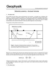
The seismometer as a forced oscillator<br />
The seismometer equation<br />
Transfer function, resonance<br />
Broadband sensors, accelerometers<br />
Dynamic range and generator constant<br />
Rotation sensors<br />
Strainmeters<br />
Tiltmeters<br />
Global Positioning System (GPS)<br />
Ocean Bottom Seismometers (OBS)<br />
Data examples, measurement principles, interconnections, accuracy,<br />
domains of application
<strong>Seismic</strong> instruments<br />
Spring-mass seismometer<br />
vertical motion<br />
Before Before we we look look more more carefully at at<br />
seismic instruments we we ask ask<br />
ourselves what what to to expect for for a<br />
typical typical spring spring based based seismic<br />
inertial sensor. This This will will highlight<br />
several fundamental issues issues we we<br />
have have to to deal deal with with concerning<br />
seismic data data analysis.
<strong>Seismic</strong> instruments<br />
Seismometer – The basic principles<br />
x 0<br />
x r<br />
x<br />
x<br />
x m<br />
u<br />
x 0<br />
u g<br />
u m<br />
u<br />
x r<br />
mass<br />
x 0<br />
ground displacement<br />
displacement of seismometer<br />
mass equilibrium position
<strong>Seismic</strong> instruments<br />
Seismometer – The basic principles<br />
The motion of the seismometer mass as a<br />
function of the ground displacement is<br />
given through a differential equation<br />
resulting from the equilibrium of forces (in<br />
rest):<br />
x 0<br />
x r<br />
F spring<br />
+ F friction<br />
+ F gravity<br />
= 0<br />
x<br />
for example<br />
.<br />
F sprin<br />
=-k x, k spring constant<br />
..<br />
F friction<br />
=-D x, D friction coefficient<br />
u g<br />
F gravity<br />
=-mu, m seismometer mass
<strong>Seismic</strong> instruments<br />
Seismometer – The basic principles<br />
using the notation introduced above the<br />
equation of motion for the mass is<br />
ẍ r<br />
t 2ε ẋ r<br />
t <br />
¿+ϖ 0 2 x r t =−ü g t <br />
x 0<br />
x<br />
x r<br />
From this we learn that:<br />
- for slow movements the acceleration<br />
and<br />
velocity becomes negligible, the<br />
seismometer records ground<br />
acceleration<br />
u g<br />
- for fast movements the acceleration of<br />
the<br />
mass dominates and the seismometer<br />
records ground displacement
A simple finite-difference solution of the seismometer equation<br />
<strong>Seismic</strong> instruments
<strong>Seismic</strong> instruments<br />
Seismometer – examples<br />
x 0<br />
x<br />
x<br />
r<br />
u<br />
g
<strong>Seismic</strong> instruments<br />
Varying damping constant<br />
x 0<br />
x<br />
x<br />
r<br />
u<br />
g
<strong>Seismic</strong> instruments<br />
Seismometer – Calibration<br />
1. How can we determine the damping<br />
properties from the observed behaviour of<br />
the seismometer?<br />
x 0<br />
x<br />
x<br />
r<br />
2. How does the seismometer amplify the<br />
ground motion? Is this amplification<br />
frequency dependent?<br />
u<br />
g<br />
We need to answer these question in<br />
order to determine what we really want to<br />
know:<br />
The ground motion.
Seismometer – Release Test<br />
1. How can we determine the damping<br />
properties from the observed<br />
behaviour of the seismometer?<br />
x 0<br />
u<br />
x<br />
x<br />
r<br />
ẍ r (t )+hϖ 0 ẋ r (t )+ϖ 0 2 x r (t )=0<br />
g<br />
x r<br />
( 0)=x 0<br />
, ẋ r<br />
(0)=0<br />
We release the seismometer mass from a given initial<br />
position and let it swing. The behaviour depends on<br />
the relation between the frequency of the spring and<br />
the damping parameter. If the seismometers<br />
oscillates, we can determine the damping coefficient<br />
h.<br />
<strong>Seismic</strong> instruments
<strong>Seismic</strong> instruments<br />
Seismometer – Release Test<br />
1<br />
F 0 = 1 H z , h = 0<br />
1<br />
F 0 = 1 H z , h = 0 .2<br />
D is p la c e m e n t<br />
0 .5<br />
0<br />
-0 .5<br />
0 .5<br />
0<br />
-0 .5<br />
x 0<br />
u<br />
g<br />
x<br />
x<br />
r<br />
-1<br />
0 1 2 3 4 5<br />
-1<br />
0 1 2 3 4 5<br />
1<br />
F 0 = 1 H z , h = 0 .7<br />
1<br />
F 0 = 1 H z , h = 2 .5<br />
D is p la c e m e n t<br />
0 .5<br />
0<br />
-0 .5<br />
0 .5<br />
0<br />
-0 .5<br />
-1<br />
0 1 2 3 4 5<br />
Tim e (s )<br />
-1<br />
0 1 2 3 4 5<br />
Tim e (s )
<strong>Seismic</strong> instruments<br />
Seismometer – Release Test<br />
a k<br />
a k+1<br />
The damping<br />
coefficients can be<br />
determined from the<br />
amplitudes of<br />
consecutive extrema a k<br />
and a k+1<br />
We need the logarithmic<br />
decrement L<br />
Λ=2ln<br />
( a k<br />
a k+1)<br />
x 0<br />
u<br />
g<br />
x<br />
x<br />
r<br />
The damping constant h can then be determined through:<br />
h=<br />
Λ<br />
√4π 2 +Λ 2
<strong>Seismic</strong> instruments<br />
Seismometer – Frequency<br />
a k<br />
a k+1<br />
T<br />
x 0<br />
x<br />
x<br />
r<br />
u<br />
g<br />
The period T with which the seismometer<br />
mass oscillates depends on h and (for h
<strong>Seismic</strong> instruments<br />
Seismometer – Response Function<br />
2. How does the seismometer amplify the ground<br />
motion? Is this amplification frequency dependent?<br />
x 0<br />
x<br />
x<br />
r<br />
To answer this question we excite our<br />
seismometer with a monofrequent signal and<br />
record the response of the seismometer:<br />
u<br />
g<br />
ẍ r (t )+hϖ 0 ẋ r (t )+ϖ 0 2 x r (t )=ϖ 2 A 0 e i<br />
ϖt<br />
the amplitude response A r<br />
of the seismometer<br />
depends on the frequency of the seismometer w 0<br />
,<br />
the frequency of the excitation w and the damping<br />
constant h:<br />
∣ A r<br />
A 0<br />
∣=<br />
1<br />
√( T 2 )2<br />
2<br />
T −1 +4h 2 T 2<br />
2<br />
0<br />
T 0
<strong>Seismic</strong> instruments<br />
Amplitude Response Function - Resonance
Phase Response<br />
<strong>Seismic</strong> instruments<br />
Clearly, the amplitude and<br />
phase response of the<br />
seismometer mass leads to a<br />
severe distortion of the original<br />
input signal (i.e., ground<br />
motion).<br />
Before analysing seismic signals<br />
this distortion has to be revered:<br />
-> Instrument correction
<strong>Seismic</strong> instruments<br />
Seismometer as a Filter<br />
Restitution -> Instrument correction
<strong>Seismic</strong> instruments<br />
Seismometer as a Filter<br />
Restitution -> Instrument correction
<strong>Seismic</strong> instruments<br />
Electromagnetic Seismograph<br />
Electromagnetic seismographs<br />
measure ground velocity
<strong>Seismic</strong> instruments<br />
The STS-2 Seismometer<br />
www.kinemetrics.com
<strong>Seismic</strong> instruments<br />
Accelerometer<br />
force-balance principle<br />
Feedback circuit of a force-balance accelerometer (FBA). The motion<br />
of the mass is controlled by the sum of two forces: the inertial force<br />
due to ground acceleration, and the negative feedback force. The<br />
electronic circuit adjusts the feedback force so that the two forces very<br />
nearly cancel. (Source Stuttgart University)
<strong>Seismic</strong> instruments<br />
<strong>Seismic</strong> signal and noise<br />
The observation of seismic noise had a strong<br />
impact on the design of seismic instruments,<br />
the separation into short-period and long-period<br />
instruments and eventually to the development<br />
of broadband sensors.
<strong>Seismic</strong> instruments<br />
<strong>Seismic</strong> noise
<strong>Seismic</strong> instruments<br />
Seismometer Bandwidth<br />
Today most of the<br />
sensors of permanent<br />
and temporary seismic<br />
networks are broadband<br />
instruments such as the<br />
STS1+2.<br />
Short period instruments<br />
are used for local<br />
seismic events (e.g., the<br />
Bavarian seismic<br />
network).
<strong>Seismic</strong> instruments<br />
(Relative) Dynamic range<br />
Dynamic Range DR: the ratio between largest measurable<br />
amplitude A max<br />
to the smallest measurable amplitude A min<br />
.<br />
DR = V max<br />
/V min<br />
Units Units … what what is is 1 Bell? Bell?<br />
… it it is is the the Base Base 10 10 Logarithm of of the the ratio ratio of of two two<br />
energies<br />
L= L= log log (P (P 1<br />
/P<br />
1<br />
/P 2<br />
)<br />
2<br />
) B = 10 10 log log (P (P 1<br />
/P<br />
1<br />
/P 2<br />
)<br />
2<br />
) dB dB<br />
Where Where B is is a 10th 10th of of B, B, and and in in terms terms of of amplitudes<br />
L = 10 10 log log (A (A 1<br />
/A<br />
1<br />
/A 2<br />
)<br />
2<br />
) 2 2 dB dB = 20 20 log log (A (A 1<br />
/A<br />
1<br />
/A 2<br />
)<br />
2<br />
)
<strong>Seismic</strong> instruments<br />
(Relative) Dynamic range<br />
Nature:<br />
The Earth has motions varying 10 orders of magnitude<br />
from the strongest motion to the lowest noise level<br />
-> DR Earth<br />
= 20 log (10 10 )dB = 200 dB !<br />
<strong>Instruments</strong>: e.g., e.g., 10 10 bit bit digitizer<br />
Dynamic range range = 20 20 log log 10<br />
(A<br />
10<br />
(A max<br />
/A<br />
max<br />
/A min<br />
)<br />
min<br />
) dB dB<br />
Example: with with 1024 1024 units units of of amplitude (A (A min<br />
=1,<br />
min<br />
=1,<br />
A max<br />
=1024)<br />
max 20 20 log log 10<br />
(1024/1)<br />
10 dB dB ~ 60 60 dB dB
<strong>Seismic</strong> instruments<br />
Bits, counts, dynamic range
<strong>Seismic</strong> instruments<br />
Dynamic range of a seismometer<br />
ADC (analog-digital-converter)<br />
A n-bit n-bit digitzer will will have have 2 n-1 n-1 intervals to to<br />
describe an an analog analog signal. signal.<br />
Seismogram<br />
data in counts<br />
Example:<br />
A 24-bit 24-bit digitizer has has 5V 5V maximum output output<br />
signal signal (full-scale-voltage)<br />
The The least least significant bit bit (lsb) (lsb) is is then then<br />
lsb lsb = 5V 5V // 2 n-1 n-1 = 0.6 0.6 microV microV<br />
Generator constant STS-2: STS-2: 750 750 Vs/m Vs/m<br />
What What does does this this imply imply for for the the peak peak ground ground<br />
velocity at at 5V? 5V?
<strong>Seismic</strong> instruments<br />
Rotation: the curl of the wavefield<br />
(ω x<br />
ω y<br />
ω z<br />
)= 1 2 ∇×v= 1 2<br />
(∂ y<br />
v z<br />
−∂ z<br />
v y<br />
∂ z v x −∂ x v<br />
x)<br />
z<br />
∂ x<br />
v y<br />
−∂ y<br />
v<br />
v z<br />
ω y<br />
ω x<br />
v y<br />
v x<br />
ω z<br />
Ground velocity<br />
Rotation rate<br />
Rotation sensor<br />
Seismometer
<strong>Seismic</strong> instruments<br />
How can we observe rotations?<br />
-> ring laser<br />
Ring laser technology developed by the<br />
groups at the Technical University<br />
Munich and the University of<br />
Christchurch, NZ
<strong>Seismic</strong> instruments<br />
Ring laser – the principle<br />
Δf Sagnac = 4Ω⋅A<br />
λP<br />
A<br />
surface of of the the ring ring laser (vector)<br />
Ω imposed rotation rate rate (Earth‘s rotation +<br />
earthquake +...) +...)<br />
λ<br />
laser wavelength (e.g. (e.g. 633 633 nm) nm)<br />
Pperimeter (e.g. (e.g. 4-16m)<br />
∆f ∆f Sagnac frequency (e.g. (e.g. 348,6 Hz Hz sampled at at<br />
1000Hz)
<strong>Seismic</strong> instruments<br />
The Sagnac Frequency<br />
(schematically)<br />
Sagnac frequency sampled with 1000Hz<br />
Tiny changes in in the the<br />
Sagnac<br />
frequencies are are<br />
extracted to to<br />
obtain the the time<br />
series with<br />
rotation rate rate<br />
Rotation rate sampled with 20Hz<br />
Df Df -> -> Q
The ring laser at Wettzell<br />
<strong>Seismic</strong> instruments<br />
ring laser<br />
Data accessible at www.rotational-seismology.org
<strong>Seismic</strong> instruments<br />
The Pinon Flat Observatory sensor
<strong>Seismic</strong> instruments<br />
PFO
<strong>Seismic</strong> instruments<br />
Rotation from seismic arrays?<br />
... by finite differencing ...<br />
ω z<br />
≈∂ x<br />
v y<br />
−∂ y<br />
v x<br />
seismometers<br />
ω z<br />
v y<br />
v x<br />
v y<br />
v x<br />
v y<br />
v x<br />
v y<br />
v x<br />
Rotational motion<br />
estimated from<br />
seismometer recordings
<strong>Seismic</strong> instruments<br />
Direct vs. array-derived rotation
Array vs. direct measurements<br />
Wassermann et al., 2009, BSSA<br />
<strong>Seismic</strong> instruments
<strong>Seismic</strong> instruments<br />
Strain sensors<br />
Network in EarthScope
<strong>Seismic</strong> instruments<br />
Pinon Flat Observatory, CA
<strong>Seismic</strong> instruments<br />
Strain meter principle
<strong>Seismic</strong> instruments<br />
Strain - Observations
<strong>Seismic</strong> instruments<br />
Tiltmeters<br />
• Tiltmeters are designed to<br />
measure changes in the angle<br />
of the surface normal<br />
• These changes are particularly<br />
important near volcanoes, or in<br />
structural engineering<br />
• In the seismic frequency band<br />
tiltmeters are sensitive to<br />
transverse acceleration<br />
Source: USGS
<strong>Seismic</strong> instruments<br />
Tilt vs. horizontal acceleration<br />
Earthquake recorded at Wettzell, Germany
<strong>Seismic</strong> instruments<br />
GPS Sensor Networks
<strong>Seismic</strong> instruments<br />
San Francisco GPS Network<br />
Co-seismic displacement<br />
measured in California<br />
during an earthquake.<br />
(Source: UC Berkeley
<strong>Seismic</strong> instruments<br />
Ocean Bottom Seismometers<br />
The OB Unit is equipped with a<br />
broadband Güralp seismometer<br />
and a Differential Pressure Gauge<br />
(from Scripps Institution of<br />
Oceanography). Additionally, it<br />
measures the absolute pressure<br />
with a Paroscientific Intelligent<br />
Depth sensor, manufactured by<br />
DIGIQUARZ.<br />
Source: GFZ Potsdam<br />
Source: USGS
<strong>Seismic</strong> instruments<br />
Ocean Bottom Seismometers<br />
RHUM-RUM<br />
Investigating La Réunion<br />
mantle plume<br />
www.rhum-rum.net<br />
Source: USGS
<strong>Seismic</strong> instruments<br />
Other sensors and curiosities<br />
• Gravimeters<br />
• Ground water level<br />
• Electromagnetic measurements<br />
(ionosphere)<br />
• Infrasound measurements
<strong>Seismic</strong> instruments<br />
Summary<br />
• Seismometers are forced oscillators, recorded<br />
seismograms have to be corrected for the instrument<br />
response<br />
• Strains and rotations are usually measured with optical<br />
interferometry, the accuracy is lower than for standard<br />
seismometers<br />
• The goal in seismology is to measure with one<br />
instrument a broad frequency and amplitude range<br />
(broadband instruments)<br />
• Cross-axis sensitivity is an important current issue<br />
(translation – rotation – tilt)