Signal Adapter SA-1 User Manual - G LAB
Signal Adapter SA-1 User Manual - G LAB
Signal Adapter SA-1 User Manual - G LAB

Create successful ePaper yourself
Turn your PDF publications into a flip-book with our unique Google optimized e-Paper software.
Version 1.0<br />
Table of contents<br />
Structure __________________________________________________________ 4<br />
Power supply ______________________________________________________ 6<br />
Way of connecting __________________________________________________ 7<br />
Setting ATTENUATION and BOOST regulators _________________________ 11<br />
Mounting_________________________________________________________ 12<br />
Technical parameters ______________________________________________ 13<br />
EMC/EMI & Certificate of conformity __________________________________ 14<br />
1
Dear Customer!<br />
Thank you for choosing our product.<br />
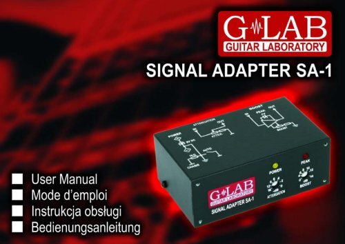
G <strong>LAB</strong> <strong>Signal</strong> <strong>Adapter</strong> <strong>SA</strong>-1 serves to adjust signal level appearing on the amp<br />
effect loop to the level required by the effects. If the signal level is too high it causes<br />
distortions and if it is too low it increase noise level and even causes inaction of some<br />
of the effects (e.g. for compressor). Adjustment of the signal is realized by two<br />
separated modules: ATTENUATION and BOOST.<br />
Basic characteristics:<br />
- Fully passive ATTENUATION module working in the range up to -16 dB (/6)<br />
- BOOST module based on class A amp working in the range from 0 to 14 dB (x5)<br />
- High level (19 dBu, 19Vpp) of the BOOST module transmitted signal<br />
- PEAK indicator of crossing the BOOST module maximal signal level (>18 dBu)<br />
- Possibility to install in the rack with the use of the G<strong>LAB</strong> 1U RMS FRONT<br />
PANEL.<br />
3
Structure<br />
4
1 ATTENUATION regulator 6 BOOST module input connector<br />
2 BOOST regulator 7 ATTENUATION module output connector<br />
3 Power supply indicator 8 ATTENUATION module input connector<br />
4 PEAK indicator (>18 dBu) 9 9V power supply connector<br />
5 BOOST module output connector<br />
If the signal level is to high adapter enables to attenuate the signal sent to the<br />
effect and to reinforce the return signal.<br />
5
If the signal level is to low adapter enables to reinforce the signal sent to the<br />
effect and to attenuate the return signal.<br />
Power supply<br />
The <strong>SA</strong>-1 should be supplied from external regulated 9V DC power supply, with<br />
capacity of 20 mA or more. It is recommended to use separated source e.g. G <strong>LAB</strong><br />
PB-1 in order to avoid ground loop. Before connecting check the connector’s<br />
polarization.<br />
6
The device is protected against opposite polarity. If this protection switches on it is<br />
needed to disconnect the power supply and wait few minutes before reactivation of<br />
the device.<br />
ATTENTION: Damages caused by improper power supply causes loss of the warranty.<br />
Way of connecting<br />
The way of connecting the adapter to the effects loop with to high signal level is<br />
shown below.<br />
7
In case of using the looper the way of connecting the adapter to the effects loop<br />
with to high signal level is shown below.<br />
8
The way of connecting the adapter in order to adjust the signal level (in this case<br />
signal attenuation) to one of the effects is shown below.<br />
9
The way of connecting the adapter to the amp effects loop with too low signal<br />
level is show below.<br />
10
Setting ATTENUATION and BOOST regulators<br />
The ATTENUATION and BOOST regulators are placed on the <strong>SA</strong>-1’s front panel.<br />
Setting is done by using small, flat screw.<br />
If the effect posses the PEAK indicator the setting should be started by the module<br />
connected to the SEND output. For maximal utility signal (very often it is a clean<br />
tone) the regulator should be set to maximal value on which the PEAK indicator<br />
doesn’t light. Further, the regulator connected to the RETURN input should be set on<br />
similar dB value (e.g. attenuation -6 dB and boost 6 dB) in order to keep the same<br />
signal level.<br />
If the effect doesn’t posses the PEAK indicator it is needed to set the regulator of the<br />
module connected to the RETURN input to minimal value and then set the regulator<br />
of the module connected to the SEND output to maximal value on which doesn’t<br />
appear unwonted signal distortion. Further, the regulator of the module connected to<br />
the RETURN input should be set on similar dB value.<br />
11
Mounting<br />
<strong>Adapter</strong> can be installed in the 19” rack with the use of the G<strong>LAB</strong> 1U RMS<br />
FRONT PANEL – product code 00831 (see picture below).<br />
12
Technical parameters<br />
Dimensions: width 110 mm<br />
depth 65 mm<br />
high<br />
40 mm<br />
Weight<br />
0,27 kg<br />
Input impedance of the ATTENUATION module 60 kΩ<br />
Maximal signal level for ATTENUATION module 20 dBu (44Vpp)<br />
Input impedance of the BOOST module<br />
>40 kΩ<br />
Output impedance of the BOOST module 200 Ω<br />
Maximal output signal level for BOOST module 19 dBu (19 Vpp) @ 50 kΩ<br />
with load:<br />
18 dBu (17Vpp) @ 10 kΩ<br />
Power supply<br />
9V DC 20 mA<br />
(8,7 to 9,4V regulated)<br />
13
EMC/EMI & Certificate of conformity<br />
EMC/EMI<br />
This device has been designed and manufactured to conform with directives and<br />
standards in the field of safety operations and electromagnetic interference.<br />
This device uses and can radiate radio frequency energy and, if not installed and<br />
used in accordance with the instructions, may cause harmful interference to radio<br />
communications. However in spite of performing below standards there is no<br />
guarantee that interference will not occur in a particular installation. If this device<br />
does cause harmful interference to radio or television reception which can be<br />
determined by turning the device on and off, the user is encouraged to try to correct<br />
the interference by one or more of the following operations:<br />
14<br />
● Reorient or relocate the receiving antenna.<br />
● Increase the separation between the device and receiver.<br />
● Connect the device into an outlet on a circuit different from that to which<br />
the receiver is connected.<br />
● Contact with the manufacturer.<br />
● Consult the dealer for help.
Certificate of Conformity<br />
ELZAB S.A., ul. Kruczkowskiego 39, 41-813 Zabrze, Poland,<br />
hereby declares on own responsibility that the following product:<br />
<strong>Signal</strong> <strong>Adapter</strong> <strong>SA</strong>-1 (G <strong>LAB</strong> <strong>Signal</strong> <strong>Adapter</strong> <strong>SA</strong>-1)<br />
that is covered by this certificate and marked with CE 07 label conforms with<br />
following standards:<br />
PN-EN 60065:2004 Safety requirements for mains operated electronic and<br />
related apparatus for household and similar general use<br />
PN-EN 55103-1:1998 Product family standard for audio, video, audio-visual and<br />
entertainment lighting control apparatus for professional<br />
use. Part 1: Emission.<br />
PN-EN 55103-2:1998 Product family standard for audio, video, audio-visual and<br />
entertainment lighting control apparatus for professional<br />
use. Part 2: Immunity.<br />
with reference to regulations in following directives:<br />
73/23/EEC, 2004/108/EEC<br />
Issued in Zabrze, April 2009<br />
Jerzy Biernat<br />
President of the ELZAB S.A. Board of Directors<br />
15
DO NOT PLACE THIS PRODUCT INTO THE WASTE CONTAINER !<br />
This device is marked with a cross-lined waste container symbol<br />
according to 2002/96/EU Directive on Waste Electric and Electronic<br />
Equipment.<br />
Such marking informs that after usage equipment can not be<br />
trashed together with other household waste.<br />
An user obligation is to return wasted equipment to a party collecting wasted<br />
electric and electronic equipment. Parties collecting such equipment organise<br />
a system, including local collection points, shops and other units, allowing to<br />
return such equipment. This Directive assures an user free of charge utilisation<br />
of such delivered equipment.<br />
This device is made of materials which can be recycled or utilised after<br />
becoming out of use. Proper handling of wasted electric and electronic<br />
equipment reduce demand for row materials and contribute in avoiding harmful<br />
consequences for environment and health of people caused by dangerous<br />
components and not proper storing and utilising of such equipment.<br />
16<br />
<strong>User</strong> <strong>Manual</strong>, Drawing No. G56INA00