High Speed DC Circuit Breaker - G E Power Controls
High Speed DC Circuit Breaker - G E Power Controls
High Speed DC Circuit Breaker - G E Power Controls

You also want an ePaper? Increase the reach of your titles
YUMPU automatically turns print PDFs into web optimized ePapers that Google loves.
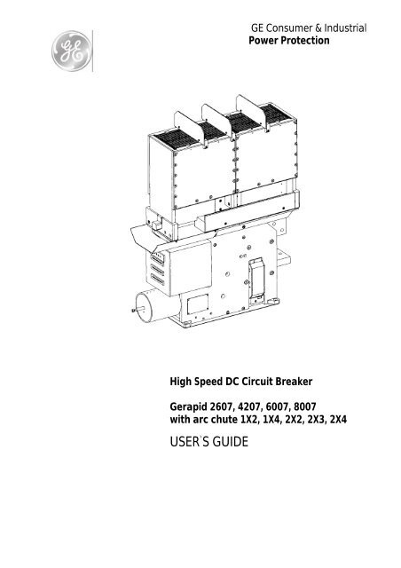
GE Consumer & Industrial<br />
<strong>Power</strong> Protection<br />
<strong>High</strong> <strong>Speed</strong> <strong>DC</strong> <strong>Circuit</strong> <strong>Breaker</strong><br />
Gerapid 2607, 4207, 6007, 8007<br />
with arc chute 1X2, 1X4, 2X2, 2X3, 2X4<br />
USER`S GUIDE<br />
S47183-e 01/2008 Design and specifications are subject to change without notice 1
INDEX<br />
1. WARNINGS AND SAFETY HINTS..............................3<br />
1.1 Warnings. ...........................................................................3<br />
1.2 Safety hints. ........................................................................4<br />
1.2.1 Securing against falling parts........................................4<br />
1.2.2 Maintenance with zero voltage release. ........................4<br />
2. GENERAL USAGE CONDITIONS...............................4<br />
2.1 Transportation...................................................................4<br />
2.2 Installation..........................................................................5<br />
2.2.1 Operational environment. .............................................5<br />
2.2.2 Installation and interfaces. ............................................5<br />
2.3 Usage...................................................................................5<br />
2.3.1 Supply and load. ...........................................................5<br />
2.3.2 Adjusting the OCT........................................................5<br />
3. TECHNICAL INFORMATIONS. ...................................6<br />
3.1 Introduction. ......................................................................6<br />
3.2 Components and accessories.............................................6<br />
3.2.1 Contact system..............................................................6<br />
3.2.2 Arc chute (code nr: 2)...................................................6<br />
3.2.3 Mechanism....................................................................7<br />
3.2.4 Over-Current Tripping device (code nr: 7)...................7<br />
3.2.5 Electro-Dynamic tripping device (code nr: 12). ...........8<br />
3.2.6 Auxiliary tripping devices (code nr: 11).......................8<br />
3.2.7 Forced tripping release (code nr: 13). ...........................8<br />
3.2.8 Hand lever (code nr: 16). ..............................................9<br />
3.2.9 Auxiliary switches (code nr: 9).....................................9<br />
3.2.10 Indicators. ...................................................................9<br />
3.2.11 Solenoid closing drive (code nr: 3)...........................10<br />
3.2.12 Current measurement system (code nr: 6). ...............10<br />
3.2.13 Electronic control system..........................................11<br />
3.3 Technical data tables. ......................................................12<br />
4. ELECTRICAL CIRCUITS...........................................14<br />
4.1 <strong>Controls</strong> layout.................................................................14<br />
5. DIMENSIONS & SAFETY DISTANCES ....................26<br />
5.1 Safety distances. .............................................................. 27<br />
5.2 Outlined dimensions........................................................ 28<br />
5.2.1 Gerapid 2607,4207, 6007 with arc chute 1x_............. 28<br />
5.2.2 Gerapid 2607, 4207, 6007with arc chute 2x_............. 29<br />
5.2.3 Gerapid 8007 with arc chute 1x_. .............................. 30<br />
5.2.4 Gerapid 8007 with arc chute 2x_. .............................. 31<br />
5.2.5 Gerapid 2607, 4207 with H / H terminals. ................. 32<br />
5.2.6 Gerapid 2607, 4207 with V / V terminals. ................. 33<br />
5.2.7 Gerapid 6007 terminals. ............................................. 34<br />
5.2.8 Gerapid 8007 terminals. ............................................. 35<br />
6. INSPECTIONS AND MAINTENANCE .......................36<br />
6.1 List of inspections............................................................ 36<br />
6.1.1 General visual inspection. .......................................... 37<br />
6.1.2 General functional inspection..................................... 37<br />
6.1.3 Inspection of the arc chute. ........................................ 37<br />
6.1.4 Inspection of the contact system. ............................... 38<br />
6.1.5 Inspection of contacts’ tilt and gap............................. 39<br />
6.1.6 Inspection of the screw connections........................... 39<br />
6.1.7 Inspection of the mechanic components..................... 39<br />
6.2 List of maintenance works.............................................. 40<br />
6.2.1 Maintenance of contact system (after 11/2003). ........ 40<br />
6.2.2. Maintenance of contact system (before 11/2003)...... 42<br />
6.2.3 Layout of control PCBs inside control box. ............... 44<br />
6.2.4 Replacement of the control boards............................. 44<br />
6.2.5 Adjusting the auxiliary switches. ............................... 46<br />
6.3 Spare parts list................................................................. 47<br />
7. CUSTOMER SUPPORT.............................................48<br />
7.1 PST coding system........................................................... 48<br />
7.2 Ordering Form. ............................................................... 49<br />
7.2.1 Example of order 1..................................................... 50<br />
7.2.1 Example of order 2..................................................... 51<br />
7.3 Glossary ........................................................................... 52<br />
7.4 Troubleshooting. ............................................................. 53<br />
4.2 Terminals wiring system. ................................................15<br />
4.3 Electrical diagrams..........................................................16<br />
4.3.1 Wiring coding system. ................................................16<br />
4.3.2 Voltage converter........................................................17<br />
4.3.3 ED coil with external capacity bank. ..........................18<br />
4.3.4 NEKO control unit......................................................19<br />
4.3.5 SU control unit............................................................20<br />
4.3.6 Shunt trip control unit.................................................21<br />
4.3.7 Zero voltage release control unit.................................22<br />
4.3.8 Indicators. ...................................................................23<br />
4.3.9 Auxiliary switches. .....................................................24<br />
4.3.10 SEL Measuring system 25<br />
2 Design and specifications are subject to change without notice S47183-e 01/2008
1. Warnings and Safety Hints<br />
1.1 Warnings<br />
During operation, electrical equipment carries dangerous<br />
voltages. In addition, circuit breaker emits hot, ionized<br />
gases when switching currents, especially short circuit<br />
currents.<br />
Installing, commissioning, maintaining, changing or refitting<br />
of this equipment must be carried out only by qualified<br />
and suitably trained personnel and under strict observation<br />
of national and international applicable safety<br />
regulations.<br />
During their operation, circuit breakers must be equipped<br />
with appropriately fitted covers, e.g. in suitable enclosures<br />
or panel boards. Safety distances must be preserved.<br />
Suitably trained service personnel shall only carry out certain<br />
works.<br />
Non-compliance with these warnings may result in death,<br />
and/or severe physical damage and extensive damage to<br />
equipment.<br />
Prior to carrying out maintenance, inspection or checks,<br />
the circuit breaker must be open, the both terminals must<br />
be grounded, the circuit breaker must be switched off and<br />
the control plugs removed.<br />
During breakers’ operation, manually activation of the<br />
breaker is forbidden. Manual activation must only be used<br />
for maintenance and inspection purposes, when breaker<br />
is power off and grounded.<br />
The circuit breaker consists of high energy moving components.<br />
Do not touch the circuit breaker while it is being<br />
switched ON (closing) or OFF (opening). There is a high risk<br />
of major injury.<br />
The control circuits may be equipped with capacitors<br />
bank, which may be charged with dangerous voltages.<br />
Work on this section must be carried out carefully.<br />
S47183-e 01/2008 Design and specifications are subject to change without notice 3
1.2 Safety hints<br />
1.2.1 Securing against falling parts<br />
Hint 1: Place a cloth into the lower area of the pre-arcing<br />
contact [Fig. 1]. Remember to secure the closing drive<br />
according to Hint 3.<br />
2. General usage conditions<br />
2.1 Transportation<br />
• The breaker is transported on wooden palette. It is fixed<br />
by shrunken plastic film. A paper cardboard box covers<br />
the breaker on the palette. Truck, railway, airplane and<br />
ship transport is possible. In case of sea transport, special<br />
protection against salty and humid environment is<br />
used.<br />
• The circuit breaker must always be transported to the<br />
installation site vertically and fully packed. The packaging<br />
protects the device against damage and dust; it<br />
should only be removed prior to installation.<br />
• If the packaging is damaged, the breaker and the arc<br />
chute must be inspected for damage. Ensure that all<br />
packaging materials have been carefully removed prior<br />
to breaker installation.<br />
• For handling the unpacked breaker [Fig. 3], use a transportation<br />
belts and reach them below the closing drive<br />
(a) and below the lower terminal (b).<br />
• Listen, that the basement isolation of the unpacked<br />
breaker during handling will not be damaged (for example<br />
don’t push the breaker back and forth at rough surface).<br />
Fig.1 Protecting of the arcing area aginst falling parts<br />
1.2.2 Maintenance with zero voltage release<br />
Hint 2: In case, when the zero voltage release is installed<br />
in, it shall be energized to enable closing of the breaker.<br />
Only then maintenance of the pre-arcing contacts is<br />
possible.<br />
Hint 3: To prevent the risk of injury, it is recommended to<br />
secure the close position of the breaker with a mechanical<br />
interlock device [Fig. 2]. The tube shall have ~50mm<br />
[~2in] length and inner diameter of minimum 14mm<br />
[0,55in]. The outer diameter of the locking rod shall be<br />
less 8mm [0,3in]. GE does not offer this locking device.<br />
a<br />
b<br />
Closing drive<br />
Secure tube<br />
Locking rod<br />
SW 6<br />
Fig. 2 Securing closing drive against opening<br />
Fig. 3 Handling the breaker and setting of the OCT unit<br />
4 Design and specifications are subject to change without notice S47183-e 01/2008
2.2 Installation<br />
2.2.1 Operational environment<br />
• The breaker, as delivered, is IP00 protected. It is intended<br />
to work in indoor applications, without pollutions, with<br />
non-conductive dust, protected against high humidity<br />
and condensation. Low conductivity dust deposit due to<br />
frequent condensation of humidity is acceptable. General<br />
environmental conditions refer to EN 50123-1 - annex<br />
B, and IEC60947, class PD3.<br />
• The breaker can operate within ambient temperature<br />
range of –5°C…+40°C (23...104°F). With decreased nominal<br />
current, breaker can operate up to +60°C (140°F).<br />
• The breaker can operate at altitude up to 2000m<br />
(~6500ft).<br />
• The breaker shall not be subjected to strong vibrations.<br />
Vibrations of 0.5g per 30sec in vertical and horizontal directions<br />
are allowed.<br />
• Air shall be clean and its relative humidity shall be not<br />
more than 50 % r.h. at the maximum temperature of<br />
+40°C (104°F). Relative humidity may be higher if the<br />
temperatures are lower, for example, 90 %r.h. at +20°C<br />
(68°F). Slight condensation might occur during variations<br />
of temperature<br />
2.2.2 Installation and interfaces<br />
• The lower and upper connections (code nr: 4) must be<br />
connected directly to the main cables or bus bars. The<br />
breaker must only be used in an upright operation position<br />
with the arc chute in place and fully secured.<br />
• After installation, both the arc chute and special<br />
threaded joints must be checked for tightness.<br />
• The safety distances as shown in the dimensional drawings<br />
must be maintained to grounded or insulated parts.<br />
Suitable measures must be taken to protect personnel<br />
from arcs.<br />
• Strong, external magnetic fields, caused by improperly<br />
located supply conductors or tray fields from other devices,<br />
can lead to a shift of the trip setting thresholds.<br />
This may result in premature tripping, or no tripping at<br />
al, during low-level short circuit current events. This has<br />
to be accounted for when installing and operating the<br />
device with shielding added if appropriate.<br />
• The control wires must be connected to the control terminals<br />
(code nr: 19), as shown in the schematic circuit<br />
diagram (Page 14). The protective grounding wire must<br />
be connected at the marked contact.<br />
2.3 Usage<br />
2.3.1 Supply and load<br />
• In accordance with its type, the breaker has been designed<br />
for the current and voltage listed in Table 1, section<br />
3.3.<br />
• During continuous operation, breaker must be loaded<br />
with its rated current at maximum. Load currents in excess<br />
of breaker nameplate rating are allowable for brief<br />
periods. Refer to the short time currents listed in Tables<br />
1a/1b.<br />
• Do not exceed the rated operating voltage shown on the<br />
breaker’s nameplate.<br />
• The drive and the auxiliary tripping devices (code nr: 8).<br />
shall be supply within the specified control voltage<br />
range. The auxiliary-tripping devices must be loaded<br />
with the values listed in Table 2a at maximum.<br />
• Plugging or removing the auxiliary current connectors<br />
are only allowed at zero potential, no voltage (-X2<br />
:1/:2) (-X3 :4/:5) !<br />
2.3.2 Adjusting the OCT<br />
• OCT is an over-current tripping device (code nr: 7), which<br />
trips a breaker in case of overload or short circuit. This is<br />
fully adjustable, instantaneous and direct tripping device.<br />
• OCT adjustment [Fig.3], within a specific range, is realized<br />
by turning the screw 1.<br />
• Adjusting procedure requires an SW6 hexagon wrench<br />
2.<br />
• The adjustment must only be carried out after the<br />
breaker has been disconnected from the main circuit<br />
and has been grounded.<br />
• Turning the adjustment screw clockwise increased the<br />
trip threshold, turning the screw counter-clockwise decreased<br />
the tripping threshold.<br />
• Aligning the arrow and the marking into one line 3 performs<br />
adjustment.<br />
S47183-e 01/2008 Design and specifications are subject to change without notice 5
3. Technical informations<br />
3.1 Introduction<br />
• Gerapid is a high-speed <strong>DC</strong> circuit breaker. This is a single-pole<br />
<strong>DC</strong> breaker, primarily designed for use in railway<br />
propulsion-power distribution systems with operating<br />
currents up to 8000A (code nr: 1) and operating voltages<br />
up to 3600V (code nr: 2). Additional application areas<br />
are special industrial plants as electrolysis plants,<br />
mines or steel mills.<br />
• The breaker type Gerapid has a very high interruption<br />
capacity combined with a current limiting characteristic.<br />
The arc chute works on the basis of an asbestos-free arc<br />
splitting principle.<br />
• A wide variety of accessories and spares are available<br />
for maintenance, repair, or as a possible extension. The<br />
breaker shall be configured by using PST coding system,<br />
available at the end of this instruction or as an excel<br />
file, free of charge.<br />
• Closing of the circuit breaker is performed through a<br />
high-power solenoid drive (code nr: 3).<br />
• During inspections, opening and closing may be carried<br />
out by means of a hand lever (code nr: 16), which is<br />
mounted onto the armature of the closing drive.<br />
• Overload tripping is obtained directly via OCT device<br />
(code nr: 7) or, optionally by electro-dynamic coil (code<br />
nr: 12). Indirect remote tripping can be achieved by<br />
means of a shunt trip or exclusively, by a zero voltage<br />
release (code nr: 11).<br />
• Gerapid breakers have a compact and enclosed construction<br />
[Fig. 4]. They are IP 00 protected. All parts are<br />
mounted on thick-walled, non-breakable and fireproof<br />
insulation panels.<br />
3.2 Components and accessories<br />
3.2.1 Contact system<br />
• Gerapid breakers are equipped with a two-stage contact<br />
system [Fig. 5], consists of a main contact and an<br />
arcing contact. With this proven design of the contact<br />
system, the main contact is not subjected to any wear or<br />
tear.<br />
• The main contacts are coated with a silver, composite<br />
material. The arcing contact and link braid are made<br />
from copper and can be easily replaced.<br />
• The flexible bend is linked to the arcing contact by<br />
means of very tight braid.<br />
Braid<br />
Flexible band<br />
Arc runner<br />
Arcing contact<br />
Main contact<br />
Fig. 5 Contact system: new (upper) and old (lower) type<br />
3.2.2 Arc chute (code nr: 2)<br />
Fig. 4 Modular construction overview<br />
• Compact and modular design of the arc system requires<br />
no additional magnetic support and allows smaller<br />
safety distances with high breaking capacity.<br />
• Because of the new compact dimensions these breakers<br />
can be installed in extremely small enclosures (from<br />
600mm; 2ft) and offers a cost-effective solution for replacements.<br />
• An adaptor is used to mount the various arc chutes for<br />
different operating voltages to the breakers.<br />
• The arc chutes consist of a highly durable, arc-proof material,<br />
wherein the arc plates have been integrated.<br />
• The arc plates split the arc into partial arcs and increase<br />
the arcing voltage by multiplying the anode and cathode<br />
voltage drop. Because of their high heat capacity,<br />
the plates and arc chute walls absorb a large amount of<br />
the arc’s energy.<br />
6 Design and specifications are subject to change without notice S47183-e 01/2008
3.2.3 Mechanism<br />
• The Gerapid is equipped with a modular designed<br />
mechanism, wear-resistant and nearly maintenancefree.<br />
This mechanism ensures an extended electrical<br />
and mechanical endurance of the breaker as well as a<br />
high amount of safety for all operation conditions.<br />
• This mechanism is mechanically latched in CLOSE position.<br />
The principle of a mechanical latch mechanism offers<br />
the big advantage, contrary to often used holding<br />
magnet system. No auxiliary control power source is required<br />
to keep close.<br />
• The mechanism is provided with two latches [Fig. 6]. One<br />
of the latches, “slow latch”, is used for opening under<br />
normal conditions, like actuation of shunt trip or zerovoltage<br />
release. The other one, “quick latch”, de-clutches<br />
the main contact arm from the mechanism and open<br />
contacts with an extremely short delay. This is used in<br />
case of short-circuit or overloads. All safety releases operate<br />
onto this latch.<br />
3.2.4 Over-Current Tripping device (code nr: 7)<br />
• The OCT device is a release magnet with twin magnet<br />
circuits, optimizing the twin magnetic field principle [Fig.<br />
7]. This technology ensures an equally fast tripping in<br />
both current directions.<br />
• The magnetic system does not require an auxiliary control<br />
voltage to operate. It uses magnetic energy from the<br />
main circuit.<br />
• The system consists of the holding circuit [6], the movable<br />
armature [3] and the tripping circuit [7]. The holding<br />
and the tripping magnetic circuits are both excited by<br />
main current [1]. Until the static overload release’s response<br />
threshold has been reached, the armature [3] is<br />
held in position by the holding flux (ΦH) [2] and the<br />
counter spring’s force [4]. Once the main current exceeds<br />
the set static response threshold, the attraction<br />
flux (ΦA) [2] takes over and pulls rapidly down the flexible<br />
armature [3]. During this operation, the armature hit<br />
the seesaw, which releases the quick latch in the<br />
mechanism. The latch and contacts are opened immediately.<br />
• The response threshold can be easily adjusted by turning<br />
the adjustment nut with a SW6 hexagon wrench as<br />
described in point 2.3.2.<br />
• In combination with the transparent side protection<br />
covers (code nr: 15), a fixed mounted insulated knob is<br />
available to enable OCT adjusting [Fig. 16].<br />
6<br />
Fig. 6 Latching and tripping system<br />
7<br />
1. Current flow direction.<br />
2. Magnetic core with two fluxes (holding flux ΦH and attracting flux ΦA).<br />
3. Movable anchor.<br />
4. Pressure spring for movable anchor.<br />
5. Short circuit rings.<br />
6. Holding magnetic circuit.<br />
7. Tripping magnetic circuit.<br />
Fig. 7 OCT device<br />
S47183-e 01/2008 Design and specifications are subject to change without notice 7
3.2.5 Electro-Dynamic tripping device (code nr: 12)<br />
• ED tripping device requires an external protective relay/system<br />
for monitoring a current increase. This relay/system<br />
belongs to customer’s installation.<br />
• If a fault occurs, an external relay, releases signal into<br />
the capacitors’ control unit (internal NEKO or external),<br />
which discharges abruptly its energy into ED coil [Fig. 8].<br />
The coil trips the breaker’s quick latch and cause opening<br />
within time of less 3ms.<br />
• ED tripping device is offered as an option. Standard set<br />
consist of ED coil and electronic control unit with C-bank<br />
installed in (NEKO). The external release signal shall have<br />
6V to 24V <strong>DC</strong>, and shall be fed at (-X2 :10 / :11).<br />
• Customer may use it’s own C-bank unit. Rated voltage of<br />
300V<strong>DC</strong> and capacity of 2000uF is required. In this case<br />
only ED coil will be installed into the breaker.<br />
• Be sure, that voltage level is between 6V…24V and<br />
there are no spikes on signal with duration 3V. In these cases UVR trips the breaker. It is therefore<br />
possible to use this device in combination with the electronic<br />
trip unit for voltage monitoring, i.e. for motor<br />
switches, where an unintended re-start of machines after<br />
a temporary voltage breakdown is to be prevented.<br />
• The UVR is intended for continuous operation. Its rated<br />
power is 40W.<br />
• Due to their operational mode, UVR is self-monitoring<br />
device, i.e. when the breaker is tripped upon a break of<br />
the pilot wire (EMERGENCY-OFF principle).<br />
Fig. 9 Zero voltage release<br />
3.2.7 Forced tripping release (code nr: 13)<br />
Fig. 8 ED tripping coil with seesaw interface<br />
• Optionally, the forced tripping release (FTU) can be installed<br />
in the breaker [Fig. 10a]. This unit is used for mechanical<br />
tripping of the breaker, by means of pressing<br />
the pin at the bottom plate. Force required to trip the<br />
breaker is about 300N (~67,5 lbf).<br />
• The tripping pin position is as on Fig. 10b.<br />
3.2.6 Auxiliary tripping devices (code nr: 11).<br />
• The breaker can be equipped with either a shunt trip (ST)<br />
or a zero voltage release (UVR). It is not possible to have<br />
both devices installed in the same breaker.<br />
• In standard configuration, internal voltage converter<br />
(code nr: 8), supply the devices with 24V<strong>DC</strong>. This converter<br />
transforms any externally connected voltage, into<br />
internal 24V<strong>DC</strong>, required by breaker’s controls.<br />
• Optionally, it’s possible to supply both devices with direct<br />
external 24V<strong>DC</strong> ± 5%. In this case release signal for ST<br />
shall not be longer 100ms.<br />
• Both devices are tripped by potential free contact connected<br />
accordingly.<br />
• Both devices are interchangeable.<br />
• The ST is used for remote actuation. It is designed for<br />
short time operation with maximum duty cycle of 9%.<br />
ST’s supply is connected through the auxiliary contact,<br />
which cut off supply voltage after breaker’s opening.<br />
This protects ST against overheating.<br />
Fig. 10a Forced tripping release<br />
(~0,6 in)<br />
(~0,3 in)<br />
8 Design and specifications are subject to change without notice S47183-e 01/2008
With correctly designed interlock in enclosure, FTU provides<br />
safety-tripping function. The breaker is tripped BEFORE its<br />
terminals are disconnected from mains, during withdraw<br />
operation of the trolley.<br />
Bottom view<br />
Fig. 11b Opening operation by using hand lever<br />
3.2.9 Auxiliary switches (code nr: 9)<br />
• The breaker can be equipped with 3, 5 or 10 isolated,<br />
form C, auxiliary switches (1 NO/NC each). The movable<br />
main arm activates the contacts.<br />
• The contacts are wired to 15-pin control terminals: -X4<br />
and -X5; 5 switches to each terminal.<br />
• Maximum electrical ratings for switches are 5A/230VAC<br />
and 0.3A/220V<strong>DC</strong>. Utilization category AC/<strong>DC</strong> 12 and 13.<br />
Fig. 10b Positioning of the forced tripping pin<br />
3.2.8 Hand lever (code nr: 16)<br />
• Optionally, hand lever for manual closing and opening<br />
operation during maintenance is available. This tool<br />
must not be use while breaker is alive!<br />
• To close the contacts, install hand lever on the drive’s<br />
rod, and pull it smoothly until latches snap [Fig. 11a].<br />
• To open the contacts, install the tool into the ring and<br />
push it hard against the drive’s rod until breaker opens<br />
[Fig. 11b].<br />
Fig. 12 Auxiliary contacts layout in control box<br />
ring<br />
Fig. 11a Closing operation by using hand lever<br />
(~45 lbf)<br />
3.2.10 Indicators<br />
Optionally, the circuit breaker can be equipped with following<br />
indicators:<br />
• POSITION INDICATOR (code nr: 14) - is mounted at the<br />
front of the closing drive. It’s mechanically switched by<br />
means of drive’s rod position. It indicates position of the<br />
main contacts. “O” – means contacts are open; “I” –<br />
means contacts are closed [Fig. 13].<br />
• OCT INDICATOR (code nr: 10) – electrical switch, the<br />
same type as in 3.2.7, mounted at the top of OCT [Fig.<br />
14]. It’s potential free, NO contact, which provides signalization<br />
of the OCT tripping.<br />
• ARC CHUTE INDICATOR (code nr: 17) – electrical switch,<br />
the same type as in 3.2, mounted on the sidewall. Indicates<br />
presence of the arc chute and blocking closing<br />
drive until arc chute is installed [Fig. 15].<br />
S47183-e 01/2008 Design and specifications are subject to change without notice 9
Position’s indicator<br />
Drive’s rod<br />
Fig. 13 Position indicator<br />
Knob<br />
Side protection<br />
Control cover box<br />
Closing drive<br />
Fig. 16 Solenoid closing drive and control box<br />
• In addition, the switch-in mechanism is electrically<br />
blocked for approximately 8sec. or 14sec. after activation<br />
(see Table 2a “Activating magnet”). This prevents<br />
premature activation following a short circuit.<br />
Fig. 14 OCT indicator<br />
3.2.12 Current measurement system (code nr: 6)<br />
• The SEL current measurement system consists of the<br />
sensing component (1) and signal-processing unit (2)<br />
[Fig.17]. SEL sensor is integrated into a specially shaped<br />
upper terminal of the breaker and is connected by a<br />
shielded cable to the signal-processing unit. SEL control<br />
unit is placed in the control-box [Fig. 18].<br />
Fig. 15 Arc chute indicator<br />
3.2.11 Solenoid closing drive (code nr: 3)<br />
• For normal closing operations, the breaker is fitted with<br />
a high power solenoid coil. The drive is mounted at the<br />
front of the breaker and is equipped with a grounded<br />
casing.<br />
• Closing drive is supplied independently from other controls<br />
(-X2 :1/:2), and directly from power source. Voltage<br />
level shall be defined at the order. Rated power depends<br />
of breaker type is between 1,8kW and 2,6kW.<br />
• CLOSING command is enable by potential free contact<br />
at (-X2 :4/:5) the signal durations shall be ~300ms.<br />
• The closing drive system always includes a self-interrupt<br />
control circuit (SU unit). This circuit enables a short activation<br />
with a time of ~150ms. SU unit switches power to<br />
the solenoid and automatically switched it off after<br />
~400ms.<br />
• SU unit prevents also repeated drive activation (antipumping),<br />
during continuous operation, due to an existing<br />
short circuit.<br />
(1) SEL sensor<br />
(2) SEL control<br />
unit<br />
Fig. 17 SEL current measurement system<br />
• SEL may be used for recording <strong>DC</strong> currents in selected<br />
measurement ranges of 6kA or 12kA. Measurement of<br />
rated current values and of the current rise may now be<br />
made directly at the breaker.<br />
10 Design and specifications are subject to change without notice S47183-e 01/2008
• The sensor includes Hall-probes and delivers a proportional<br />
signal-output to the SEL control. The signalprocessing<br />
unit transforms input signal, into standard<br />
output signals shown in the table below.<br />
• The outputs are insulated from the main voltage. The insulation<br />
withstands voltages up to 4kV RMS and up to<br />
40kV in peak.<br />
• Two versions are available. Standard model (T35) for<br />
ambient temperature -5°C…+35°C and the model for<br />
higher temperature (T55) -5°C…+55°C.<br />
• More details can be found in separate instruction for SEL<br />
usage.<br />
Type SEL 06-1 06-2 06-4 12-1 12-2 12-4<br />
Input - 6kA…+6 kA -12kA…+12kA<br />
U Ne[V] 1000 2000 4000 1000 2000 4000<br />
Fig. 19-1 NEKO control unit<br />
• (2) internal voltage converter (code nr: 8) - converts external<br />
supply voltage (-X3 :4/:5) to the internal 24V<strong>DC</strong>,<br />
required by controls (except for the drive supply).<br />
T35<br />
T55<br />
I Ne<br />
for ambient temperature of the breaker<br />
-5°C…+35°C / +23°F…+95°F<br />
for ambient temperature of the breaker<br />
-5°C…+55°C / +23°F...+131°F<br />
Relating to the rated current of the breaker<br />
Output<br />
4...20mA<br />
-20...20mA<br />
-10...10V<br />
U Ni[kV] 12 18 40 12 18 40<br />
3.2.13 Electronic control system<br />
All the control units are installed in control box [Fig. 18].<br />
Starting from the left, these are:<br />
Fig. 19-2 Voltage converter 110V/24V <strong>DC</strong><br />
• (3) SU control unit – see point 3.2.11.<br />
Fig. 19-3 SU control unit<br />
• (4) ST/UVR control unit – simple relays’ system. It controls<br />
operation of shunt trip or zero voltage release.<br />
Fig. 18 Control box with control units<br />
• (1) NEKO control unit [Fig. 19-1] – internal control unit<br />
with capacitors’ bank. It releases firing signal for ED coil<br />
(-X2 :10/:11) and enable signalization of the capacitors’<br />
charging (-X3 :6/:7). NEKO control unit also blocks the firing<br />
signal until C-bank is fully charged (~15sec).<br />
• NEKO unite requires high quality firing signal. Be sure,<br />
that voltage level is between 6V…24V and there is no<br />
short spikes on signal (
3.3 Technical data tables<br />
<strong>Breaker</strong> type<br />
Arc chute type 1X2 1X4 2X2 2X3 2X4 1X2 1X4 2X2 2X3 2X4 1X2 1X4 2X2 2X3 2X4 1X2 2X2<br />
Conventional thermal current I th [A]<br />
(IEC/EN)<br />
Rated current [A] (ANSI) 2600 4150 5000<br />
Rated voltage U e [V] 1000 2000 2000 3000 3600 1000 2000 2000 3000 3600 1000 2000 2000 3000 3600 1000 2000<br />
Rated insulation voltage U i [V] 2000 2000 2000 3000 4000 2000 2000 2000 3000 4000 1000 2000 2000 3000 4000 1000 2000<br />
Short time current 120 min [A]<br />
Short time current 2 min [A]<br />
Short time current 20 sec [A]<br />
Impulse withstand voltage 1,2/50 µs Ui [kV] 18 18 18 30 30 18 18 18 30 30 12 18 18 30 -1) 12 18<br />
according to EN 50124-1:1997<br />
<strong>Power</strong> frequency withstand voltage 50 Hz Ua [kVeff] 10 10 10 15 15 10 10 10 15 15 7 10 10 15 -1) 7 10<br />
according to EN 50124-1:1997<br />
Rated short circuit making capacity Î Nss [kA] 70 50 100 50 42 70 50 100 50 42 70 50 80 50 -1) 70 - 1)<br />
Rated short circuit breaking capacity I Nss [kA] 50 35 71 35 30 50 35 71 35 30 50 35 56 35 -1) 50 50<br />
according to EN 50123-2<br />
Rated service short circuit breaking current Ics [kA] 60 40 50 40 40 60 40 50 40 40 60 40 50 40 -1) 60 - 1)<br />
according to IEC 947-2<br />
Short circuit current [kA] at Une=800 V<strong>DC</strong> 200 200 200<br />
Short circuit current [kA] at Une=1600 V<strong>DC</strong> -1) 100 -1) -1)<br />
ANSI C37.14<br />
Maximum short circuit current [kA] 244 120 100 52 244 120 100 52 200 240<br />
tested at customer request<br />
Maximum arc voltage Uarc [kV] 2 4 4 5,6 7 2 4 4 5,6 7 2 4 4 5,6 7 2 4<br />
Weight ca. [kg] 120 120 160 160 160 120 120 160 160 160 150 150 165 165 165 190 210<br />
Weight ca. [lbs] 265 265 352 352 352 265 265 352 352 352 331 331 364 364 364 419 463<br />
Table 1: Technical data of Gerapid 2607, 4207, 6007, 8007.<br />
Gerapid 2607<br />
3150<br />
Gerapid 4207 Gerapid 6007<br />
2600 4200 6000<br />
5200<br />
5000<br />
8500<br />
7800 12600<br />
7200<br />
12000<br />
18000<br />
Gerapid 8007<br />
8000<br />
6000<br />
9600<br />
16000<br />
24000<br />
S47183-e 01/2008 Design and specifications are subject to change without notice 12
Control box terminals 1x12-pole AC 400V, 20A<br />
4x15-pole<br />
AC 250V, 8A<br />
Closing solenoid drive 1) Rated voltage AC 48V…230V and <strong>DC</strong> 48V…220V<br />
Operating range<br />
80%...115% of rated voltage<br />
<strong>Power</strong> consumption Gerapid 2607 / 4207 1750W / 2000W<br />
<strong>Power</strong> consumption Gerapid 6007 / 8007 2600W / 2600W<br />
Minimal CLOSING command duration<br />
100ms<br />
min.interval between two "CLOSE" operations ~8s with NEKO installed; ~14s w/o NEKO<br />
Internal voltage converter 1) Input: Voltage range <strong>DC</strong> 33...85V<br />
for Gerapid 2607, 4207, 6007, 8007 Output: Voltage range <strong>DC</strong> 24V (±5%)<br />
Current<br />
6A permanent<br />
Model description<br />
PCMD 150 48 S24W-GE<br />
Input: Voltage range <strong>DC</strong> 88...145V<br />
Output: Voltage range <strong>DC</strong> 24V (±5%)<br />
Current<br />
6A permanent<br />
Model description<br />
nr. PCMD 150 110 S24W-GE<br />
Input: Voltage range AC 115...290V, <strong>DC</strong> 125...353V<br />
Output: Voltage range <strong>DC</strong> 24V (±5%)<br />
Current<br />
3A permanent, 5A/100ms<br />
Model description<br />
nr. PCMA 70 S24W-GE<br />
External power supply with plug and socket unit requires extrnal 24V (±5%) <strong>DC</strong><br />
Aux. contact HS 1…HS 10, Rated operational voltage Ue/AC 230V<br />
OCT- and Arc chute- indicators Rated operational current Ie/AC-15 1A<br />
Rated operational current Ie/AC-12 (Ith) 10A<br />
Rated operational voltage Ue/<strong>DC</strong> 110V<br />
Rated operational current Ie/<strong>DC</strong>-13 0,5A<br />
Contact duty (min. value)<br />
<strong>DC</strong> 10V/2 mA<br />
ST 1) Rated voltage Uc 24V<br />
(Shunt trip) Operating range: OFF 21.6V…26.4V<br />
<strong>Power</strong> consumption<br />
~ 150W<br />
UVR 1) Rated voltage Uc 24V<br />
(Zero voltage release) Operating range: OFF < 3V<br />
Operating range: ON 24V (±10%)<br />
<strong>Power</strong> consumption<br />
~ 40W<br />
ED-tripping device 1) Energie source: Capacity 2000µF<br />
Charging voltage<br />
300V<br />
Switching interval<br />
max. 2/min with 10 consecutive operations<br />
Endurance<br />
1000 operations with 1operation per 180s<br />
Firing signal 2) level / duration 6…24V / 100…1000ms<br />
1) Standard ambient conditions acc. to EN 123-1 Attachement B. For meeting outside of this standard range, please call back.<br />
Table 2a: Technical data of auxiliary circuits<br />
Components<br />
Technical datas of control circuits<br />
Us / In<br />
SU-Control CLOSE-push-button -S1 <strong>DC</strong> 24V / approx. 10mA<br />
ST releasing push-button-S2 <strong>DC</strong> 24V / approx. 4A<br />
UVR releasing push-button -S2 ( -X2 :6 / :7) <strong>DC</strong> 24V / approx. 10mA<br />
push-button -S2 ( -X2 :8 / :9 )<br />
<strong>DC</strong> 24V / approx. 450mA<br />
ED-coil tripping w/o NEKO (R = 4Ohm) push-button -S3 <strong>DC</strong> 300V / 750A / 3ms<br />
ED-coil tripping with NEKO Connect "Firing signal" at ( -X2 :10 / :11 ) <strong>DC</strong> 6V…24V / approx.20mA<br />
Table 2b: Control circuits ( directional values to rate the components )<br />
S47183-e 01/2008 Design and specifications are subject to change without notice 13
4. Electrical circuits<br />
4.1 <strong>Controls</strong> layout<br />
Closing solenoid drive<br />
Shunt trip / Zero voltage release<br />
ED coil<br />
OCT device<br />
HS 1...HS 10<br />
OCT indicator<br />
Arc chute-indicator<br />
Description<br />
Designation<br />
X2<br />
1.Connector: Auxiliary- and control circuits<br />
X3<br />
2.Connector: Auxiliary- and control circuits<br />
X4<br />
3.Connector: Auxiliary contacts HS1...HS5<br />
X5<br />
4.Connector: Auxiliary contacts HS6...HS10<br />
X6<br />
5.Connector: Current measure system SEL<br />
X10<br />
Control board: Voltage converter<br />
X11<br />
Control board: Interface for external <strong>DC</strong> 24V supply (OPTION)<br />
X12<br />
Control board: SU control unit<br />
X13<br />
Control board: Shunt trip control unit<br />
X14, X15 Control board: Zero voltage release (X15: with modified UVR)<br />
X16<br />
Control board: NEKO control unit for ED coil control<br />
X17<br />
Control board: Current measure system SEL<br />
Fig. 20 Control system’s layout<br />
14 Design and specifications are subject to change without notice 01/2008
4.2 Terminals wiring system<br />
1 2 3 4 5 6 7 8 9 10 11 12 13 14 15<br />
X4<br />
Closing drive supply (~,+) (S3)<br />
Closing drive supply (N,-)<br />
PE<br />
S1 ( CLOSE-Command)<br />
S2 ( OPEN by ST command)<br />
S2 (OPEN by UVR command )<br />
ed-trip + ( 6,5…24V )<br />
ed-trip - ( 0V )<br />
1 2 3 4 5 6 7 8 9 10 11 12<br />
X2<br />
1 2 3 4 5 6 7 8 9 10 11 12 13 14 15<br />
X3<br />
NEKO charging indicator<br />
(indicates C-bank charging)<br />
with OCT indicator<br />
(Indicates tripping by OCT)<br />
HS 1<br />
HS 2<br />
HS 3<br />
HS 4<br />
HS 5<br />
1 2 3 4 5 6 7 8 9 10 11 12 13 14 15<br />
X5<br />
HS 6<br />
HS 7<br />
HS 8<br />
HS 9<br />
HS 10<br />
Arc chute indicator<br />
(Indicator switch)<br />
1 2 3 4 5 6 7 8 9 10 11 12 13 14 15<br />
X6<br />
SEL (self check)<br />
SEL (4…20 mA) +<br />
SEL (4…20 mA) -<br />
SEL ( +/- 20 mA) +<br />
SEL ( +/- 20 mA) -<br />
SEL ( +/- 10V ) +<br />
SEL ( +/- 10 V ) -<br />
Fig. 21 Terminals wiring system.<br />
S47183-e 01/2008 Design and specifications are subject to change without notice 15
4.3 Electrical diagrams.<br />
4.3.1 Wiring coding system.<br />
The main circuits are not shown in the wiring diagrams<br />
due to clarity. The control circuit is presented as a typical<br />
circuit diagram and is a combination of numbered basic<br />
diagrams for drives, trips and indicators.<br />
Using the key numbers of the basic plan, you can derive<br />
the number of the complete diagram.<br />
Key position:<br />
<strong>Breaker</strong> type<br />
Aux. voltage supply<br />
ED tripping device<br />
Closing drive<br />
Aux. tripping device<br />
Indicators<br />
Aux. switches<br />
SEL system<br />
EXAMPLE:<br />
Key number:<br />
Gerapid<br />
With voltage converter<br />
With ED coil and NEKO<br />
With closing drive<br />
Wtih shunt trip<br />
With OCT indicator<br />
With 5 aux. switches<br />
With SEL system<br />
1 / 2 3 4 5 6 7 8<br />
36 / 1 2 20 10 01 2 S<br />
Key Key<br />
Designation<br />
position number<br />
Type<br />
1 36 Gerapid<br />
Auxiliary voltage<br />
2 1 Voltage converter<br />
2 <strong>DC</strong> 24V external supply<br />
Tripping coil<br />
3 0 Without ed-trip coil<br />
1 With ed-trip coil<br />
2 With ed-trip coil and NEKO<br />
control unit<br />
Drive<br />
4 20 Solenoid drive with<br />
SU control unit<br />
Tripping device<br />
5 00 Without trip unit<br />
10 With shunt trip<br />
20 With zero voltage release<br />
Indication device<br />
6 00 Without indicators<br />
01 OCT indicator<br />
02 Arc chute indicator<br />
03 OCT + arc chute indicator<br />
Auxiliary contacts<br />
7 1 3 auxiliary switches<br />
2 5 auxiliary switches<br />
3 10 auxiliary switches<br />
Current-measurement system<br />
8 S with SEL<br />
Indication of components<br />
Q1<br />
S1<br />
S2<br />
<strong>Circuit</strong> breaker<br />
Push button „CLOSE“<br />
Push button „OPEN“"<br />
SU control unit:<br />
K1 Closing relay<br />
K2 Internal emergency STOP relay 1)<br />
Shunt trip, zero voltage release:<br />
K1 Internal emergency STOP relay 1)<br />
HS11 Auxiliary contact<br />
ED-tripping device with internal NEKO unit:<br />
K1 Voltage monitoring relay<br />
1) These relays are part of internal emergency STOP circuit. It<br />
is a 24V<strong>DC</strong> closed circuit, through all the control units in the<br />
box. Serial connection of all emergency relays is realized<br />
through connections ( :5/:6) in every PCB’s terminal. In case<br />
of control voltage lost or unit’s damage, circuit is locking<br />
possibility to switch ON the breaker.<br />
Fig. 22 Example of wiring code for AEG type labels.<br />
16 Design and specifications are subject to change without notice 01/2008
4.3.2 Voltage converter<br />
Voltage converter<br />
33V...353V<strong>DC</strong> / 115V...290VAC<br />
~ / +<br />
External voltage supply<br />
24V <strong>DC</strong> +/-5%<br />
Input<br />
-X10<br />
-X3<br />
<strong>DC</strong> 33V…85V <strong>DC</strong><br />
<strong>DC</strong> 88…145V <strong>DC</strong><br />
<strong>DC</strong> 125…353V <strong>DC</strong><br />
AC 115…290V AC<br />
Output <strong>DC</strong> 24V ±5%<br />
4<br />
1<br />
3<br />
10<br />
9<br />
8<br />
7<br />
6<br />
+24V<br />
-24V<br />
Emergency STOP circuit<br />
-X3<br />
4<br />
1<br />
3<br />
-X11<br />
10<br />
9<br />
8<br />
7<br />
6<br />
Emergency STOP circuit<br />
-X3<br />
5<br />
-X3<br />
5<br />
N / -<br />
- 24 V<br />
36/ X _ _ _ _ _ _<br />
Key position - 2<br />
Key number – 1: Voltage converter 33..85V <strong>DC</strong>; 88..145V <strong>DC</strong>; 125..353V <strong>DC</strong>; 115..290V AC<br />
Key number – 2: Interface for direct external voltage 24V<strong>DC</strong> +/- 5% connection.<br />
Fig. 23 Voltage converter and direct external supply (<strong>DC</strong> 24V ±5%)<br />
S47183-e 01/2008 Design and specifications are subject to change without notice 17
4.3.3 ED coil with external capacity bank<br />
• In this option customer provides his own solution for releasing of the ED coil, by means of external capacity bank. In this<br />
case NEKO control unit is not installed, and coil’s connected directly to front panel of control box (-X2 :10/:11).<br />
-S3<br />
Capacity<br />
bank:<br />
U ~300V<br />
F ~2000µF<br />
-X2<br />
:10<br />
-Q1<br />
ed<br />
-X2<br />
:11<br />
36/ _ X _ _ _ _ _<br />
Key position - 3<br />
Key number – 0: Without ED coil.<br />
Key number – 1: With ED coil and external C-bank.<br />
Fig. 24 ED coil with external C-bank<br />
18 Design and specifications are subject to change without notice 01/2008
4.3.4 NEKO control unit<br />
-X16<br />
-X10, 11<br />
+<br />
:8<br />
1<br />
<strong>Power</strong> supply<br />
24V<strong>DC</strong><br />
Insulating Transformer<br />
-<br />
-X10, 11<br />
:6<br />
2<br />
Pulse circuit<br />
Charging control<br />
-X3<br />
Output signal<br />
-bank charged<br />
-X3<br />
9<br />
:6<br />
10<br />
:7<br />
5<br />
Voltage control<br />
Emergency<br />
STOP signal<br />
6<br />
Meldeschalter<br />
-X2<br />
+<br />
3<br />
Firing signal<br />
6-24V<br />
-X2<br />
-<br />
:10<br />
:11<br />
4<br />
Firing circuit<br />
Firing signal control<br />
and transforming<br />
11<br />
Q1<br />
„ED coil”<br />
12<br />
Capacity and firing thyristor<br />
36/ _ X _ _ _ _ _<br />
• Releasing signal at (-X2 :10/:11) is processed by optocoupler, pay attentions to the polarity !<br />
• Emergency STOP signal is provided to lock CLOSE command, until capacitors will be charged.<br />
• Be sure, that voltage level is between 6V…24V and there is no interfere spikes (
4.3.5 SU control unit<br />
-Q1 Drive<br />
+ / ~<br />
-X12<br />
2<br />
1<br />
-S3<br />
-X2<br />
3<br />
:1<br />
~<br />
External power supply<br />
for the drive.<br />
-<br />
+<br />
-X2<br />
:2<br />
4<br />
~<br />
<strong>Power</strong> circuit<br />
„CLOSE“<br />
signal<br />
-X2<br />
-S1<br />
-X2<br />
:5<br />
:4<br />
9<br />
8<br />
CLOSE signal circuit<br />
Closing control<br />
:9<br />
10<br />
-X10, 11<br />
K2<br />
-X10, 11<br />
:6<br />
7<br />
Emergency STOP<br />
relay<br />
5 6<br />
N / ~<br />
Emergency<br />
STOP signal<br />
36/ _ _ X _ _ _ _<br />
Key position - 4<br />
Key number – 20: Closing solenoid drive with SU control unit.<br />
Fig. 26 SU-control circuit<br />
20 Design and specifications are subject to change without notice 01/2008
4.3.6 Shunt trip control unit<br />
Emergency STOP<br />
signal<br />
-X14<br />
5 6<br />
-K1<br />
:6<br />
4<br />
7<br />
:7<br />
-<br />
-X10, 11<br />
-S2<br />
24 V<br />
:7<br />
3<br />
A1<br />
-K1<br />
A2<br />
8<br />
:9<br />
-X10, 11<br />
+<br />
2<br />
3<br />
9<br />
-HS11<br />
C1<br />
4<br />
1<br />
10<br />
C2<br />
36/ _ _ _ X _ _ _<br />
Key position - 5<br />
Key number – 00: Without shunt trip or zero voltage release.<br />
Key number – 10: With shunt trip.<br />
• The EM-STOP signal is provided for resetting K2 on the SU-control circuit. It effects with priority in switching OFF (by ST or<br />
UVR) before switching ON. Once switching ON and OFF signals are simultaneous, switching OFF command will stay<br />
longer than switching ON. It means, that OFF command is master command.<br />
• The shunt trip operates for short time period only. After contacts opening, switch HS 11 cuts ST’s supply circuit.<br />
Fig. 27 ST control circuit<br />
S47183-e 01/2008 Design and specifications are subject to change without notice 21
4.3.7 Zero voltage release control unit<br />
-S2<br />
-X2 -X2<br />
:7 :6<br />
- X13<br />
3 4<br />
5<br />
-K2<br />
A1<br />
Emergency STOP<br />
signal<br />
-K1<br />
Emergency STOP<br />
signal<br />
A2<br />
6<br />
-<br />
7<br />
2<br />
-X2<br />
24 V<br />
+<br />
8<br />
-S2<br />
A1<br />
A2<br />
-K1 -K2<br />
1<br />
-X2<br />
-D1<br />
9 10<br />
U<<br />
36/ _ _ _ X _ _ _<br />
• The EM-STOP signal is provided for resetting K2 on the SU-control circuit. It effects with priority in switching OFF (by ST or<br />
UVR) before switching ON. Once switching ON and OFF signals are simultaneous, switching OFF command will stay<br />
longer than switching ON. It means, that OFF command is master command.<br />
• -S2 (-X2 :6/:7) is NO contact, predicted for indirect releasing of the UVR by relay -K2<br />
• -S2 (-X2 :8/:9) is NC contact predicted for direct releasing of the UVR. If it’s not used, please short this connection permanently.<br />
Fig. 28 UVR control circuit<br />
Key position - 5<br />
Key number – 00: Without shunt trip or zero voltage release.<br />
Key number – 20: With zero voltage release.<br />
22 Design and specifications are subject to change without notice 01/2008
4.3.8 Indicators<br />
-X3<br />
:8<br />
-X3<br />
:12<br />
-X3<br />
:9<br />
-X3<br />
:13<br />
OCT indicator<br />
Arc chute indicator<br />
36/ _ _ _ _ X _ _<br />
Key position - 6<br />
Key number – 00: Without indicators.<br />
Key number – 01: With OCT indicator only.<br />
Key number – 02: With arc chute indicator only.<br />
Key number – 03: With OCT and arc chute indicators.<br />
Fig. 29 OCT indicator and arc chute indicator<br />
S47183-e 01/2008 Design and specifications are subject to change without notice 23
4.3.9 Auxiliary switches.<br />
1 2 3 4 5 6 7 8 9 10 11 12 13 14 15<br />
X4<br />
HS 1<br />
HS 2<br />
HS 3<br />
HS 4<br />
HS 5<br />
1 2 3 4 5 6 7 8 9 10 11 12 13 14 15<br />
X5<br />
HS 6<br />
HS 7<br />
HS 8<br />
HS 9<br />
HS 10<br />
36/ _ _ _ _ _ X _<br />
Key position - 7<br />
Key number – 1: With 3 switches (HS1...HS3).<br />
Key number – 2: With 5 switches (HS1...HS5).<br />
Key number – 3: With 10 switches (HS1...HS10)..<br />
Fig. 30 Auxiliary switches<br />
24 Design and specifications are subject to change without notice 01/2008
4.3.10 SEL measuring system<br />
1)<br />
2)<br />
Signal<br />
Processing<br />
Unit<br />
3)<br />
Voltage<br />
stabilizer<br />
Self check control<br />
<strong>DC</strong> 24V<br />
<strong>DC</strong> 24V<br />
1) max. 500 Ω 2) max. 500 Ω 3) min. 300 kΩ<br />
36/ _ _ _ _ _ _ X<br />
Key position - 8<br />
Key number – S: With SEL measurment system.<br />
Fig. 31 SEL current measurement system<br />
S47183-e 01/2008 Design and specifications are subject to change without notice 25
5. Dimensions & safety distances<br />
Warnings<br />
During operation, all metallic parts of the breaker, except control box and<br />
closing solenoid drive, may carry dangerous voltages.<br />
Insulation covers are available as an option.<br />
For installation of the breaker into cubicle, top and side openings shall be<br />
provided, in order to reduce internal pressure rise during clearing short<br />
circuit.<br />
All openings respectively free areas on the top of the cubical shall be not<br />
less than 50%.<br />
26 Design and specifications are subject to change without notice 01/2008
5.1 Safety distances. Units call in mm (inches)<br />
Type Arc chute Main- additional Deflector Safety distances / Insulated plates Safety distances / Earthed plates<br />
Gerapid Connection isolation<br />
action E A B C D A B C D<br />
2607 / 4207 1x2 all 10 (0,4) 700 (27,6) 150 (5,9) 150 (5,9) 120 (4,7) 1000 (39,4) 300 (11,8) 300 (11,8) 300 (11,8)<br />
1x3 all 1) 1) 1) 1) 1) - - - -<br />
1x4 all 150 (5,9) 700 (27,6) 150 (5,9) 150 (5,9) 120 (4,7) 1350 (53,2) 450 (17,7) 450 (17,7) 200 (7,9)<br />
2x2 all 80 (3,15) 1000 (39,4) 300 (11,8) 300 (11,8) 300 (11,8) 1350 (53,2) 450 (17,7) 450 (17,7) 300 (11,8)<br />
2x3 all 80 (3,15) 1000 (39,4) 180 (7,1) 180 (7,1) 180 (7,1) - - - -<br />
2x4 H / H Plate 150 (5,9) 1000 (39,4) 180 (7,1) 180 (7,1) 180 (7,1) - - - -<br />
2x4 H / H Sidewalls 150 (5,9) 1000 (39,4) 180 (7,1) 180 (7,1) 180 (7,1) - - - -<br />
2x4 SEL / H Pan 150 (5,9) 1000 (39,4) 180 (7,1) 180 (7,1) 180 (7,1) - - - -<br />
6007 1x2 V / V Heat sink 10 (0,4) 1000 (39,4) 300 (11,8) 300 (11,8) 180 (7,1) - - - -<br />
1x3 1) 1) 1) 1) 1) 1) 1) - - - -<br />
1x4 V / V Heat sink 150 (5,9) 1000 (39,4) 300 (11,8) 300 (11,8) 180 (7,1) - - - -<br />
2x2 V / V Heat sink 80 (3,15) 1000 (39,4) 180 (7,1) 180 (7,1) 180 (7,1) - - - -<br />
2x3 V / V Heat sink 80 (3,15) 1000 (39,4) 180 (7,1) 180 (7,1) 180 (7,1) - - - -<br />
2x4 1) 1) 1) 1) 1) 1) 1) - - - -<br />
8007 1x2 V / V Heat sink 10 (0,4) 1000 (39,4) 300 (11,8) 300 (11,8) 180 (7,1) - - - -<br />
1x3 1) 1) 1) 1) 1) 1) 1) - - - -<br />
1x4 1) 1) 1) 1) 1) 1) 1) - - - -<br />
2) 2x2 V / V Heat sink 80 (3,15) 1000 (39,4) 180 (7,1) 180 (7,1) 180 (7,1) - - - -<br />
2) 2x3 V / V Heat sink 80 (3,15) 1000 (39,4) 180 (7,1) 180 (7,1) 300 (11,8) - - - -<br />
2x4 1) 1) 1) 1) 1) 1) 1) - - - -<br />
1) will be checked by customers order<br />
2) acc. IEC 947-2 / ks-setting
5.2 Outlined dimensions<br />
5.2.1 Gerapid 2607,4207, 6007 with arc chute 1x_<br />
Pay attention to legend, warnings and safety distances pages 26/27!<br />
Fig. 32 Gerapid 2607- 6007, arc chute 1X (dimensions in mm and inches)<br />
S47183-e 01/2008 Design and specifications are subject to change without notice 28
5.2.2 Gerapid 2607, 4207, 6007with arc chute 2x_<br />
Pay attention to legend, warnings and safety distances pages 26/27!<br />
Fig. 33 Gerapid 2607- 6007, arc chute 2x (dimensions in mm and inches)<br />
S47183-e 01/2008 Design and specifications are subject to change without notice 29
5.2.3 Gerapid 8007 with arc chute 1x_<br />
Pay attention to legend, warnings and safety distances pages 26/27!<br />
Fig. 34 Gerapid 8007 with arc chute 1x (dimensions in mm and inches)<br />
30 Design and specifications are subject to change without notice 01/2008
5.2.4 Gerapid 8007 with arc chute 2x_<br />
Pay attention to legend, warnings and safety distances pages 26/27!<br />
Fig. 35 Gerapid 8007 with arc chute 2x (dimensions in mm and inches)<br />
S47183-e 01/2008 Design and specifications are subject to change without notice 31
5.2.5 Gerapid 2607, 4207 with H / H terminals<br />
It’s able to combine connections horizontal and vertical, dimensions are corresponding.<br />
Fig. 36 Gerapid 2607, 4207 with horizontal terminals (dimensions in mm and inches)<br />
32 Design and specifications are subject to change without notice 01/2008
5.2.6 Gerapid 2607, 4207 with V / V terminals<br />
It’s able to combine connections horizontal and vertical, dimensions are corresponding.<br />
Fig. 37 Gerapid 2607, 4207 with vertical terminals (dimensions in mm and inches)<br />
S47183-e 01/2008 Design and specifications are subject to change without notice 33
5.2.7 Gerapid 6007 terminals<br />
Gerapid 6007 is available only with V / V terminals !<br />
Fig. 38 Gerapid 6007 with vertical terminals (dimensions in mm)<br />
34 Design and specifications are subject to change without notice 01/2008
5.2.8 Gerapid 8007 terminals<br />
Gerapid 8007 is available only with V / V terminals !<br />
Fig. 39 Gerapid 8007 with vertical terminals (dimensions in mm and inches)<br />
S47183-e 01/2008 Design and specifications are subject to change without notice 35
6. Inspections and maintenance<br />
6.1 List of inspections<br />
B. General functional inspection<br />
C. Inspection of the arc<br />
chute and contact system<br />
D. Inspection of the screw<br />
connections<br />
E. Inspection of the mechanic<br />
components<br />
Table 3<br />
Customer.<br />
Trained technician.<br />
Customer.<br />
Trained technician.<br />
Customer.<br />
Trained technician.<br />
GE.<br />
Service technician.<br />
TYPE OF THE INSPECTION BY WHOM HOW OFTEN WHAT TO DO/CHECK<br />
A. General visual inspection Customer.<br />
Trained technician.<br />
Every 6-12 months • Check out damages or cracks of the<br />
frame, adapter or arc chute<br />
• Check out for missing screws or caps<br />
• Check out for deglutinated labels<br />
• Check out for corrosion<br />
• Check out distinct manifestations of<br />
flame or smoke at the frame<br />
• Clean the breaker from dirt and dust<br />
• Clean and degrease the cooper terminals<br />
Every 6-12 months • Close and open manually the breaker<br />
to check the drive and mechanism<br />
• Close the breaker electrically and<br />
open by trip unit(s) releasing, to check<br />
controls<br />
Every 6-12 months<br />
OR after:<br />
• high short circuit opening<br />
at >25kA<br />
• >300 openings at load<br />
current<br />
• >100 openings at over<br />
current load (2-3 *In)<br />
Every 6-12 months<br />
OR after every inspection:<br />
• of the arc runners<br />
• of the contacts<br />
• of the arc chute<br />
Every 5 years<br />
OR<br />
After 5.000 openings<br />
• Check out wear of the arc runners;<br />
shall not exceed 30% of its cross section<br />
• Check out wear of the pre-arcing<br />
contact. It shall not exceed 2mm<br />
[0,08in].<br />
• Check out wear of the main contacts<br />
at fix and flexible side; shall not exceed<br />
1mm [0,04in] of its depth.<br />
• Check out wear of the arc chute’s<br />
plates; check out for deposits inside<br />
of arc chute, this area shall be free of<br />
deposits.<br />
• Check out wear of protective walls;<br />
shall not exceed 1mm [0,04].<br />
• Check out contacts’ tilt and gaps.<br />
Check out position of the countersunk<br />
screws in the sidewalls.<br />
Check for tight fitting or use torque tool<br />
(torque in SI and Imperial units):<br />
• M8 ~20Nm [~ 177 lbf*in]<br />
• M6 ~10Nm [~ 88 lbf*in]<br />
• M5 ~5Nm [~ 44 lbf*in]<br />
• M4 ~3Nm [~ 26 lbf*in]<br />
• Carry out inspection B<br />
• Check out settings of contacts and<br />
auxiliary switches<br />
• Check out upper dumper of the<br />
mechanism; no cracks, deformation<br />
or heavy discolouration; hard consistency;<br />
without punctures<br />
• Check out main flexband breakage;<br />
shall not exceed 30% of its cross section<br />
• Check out wear of mini flexband; shall<br />
not exceed 30% of its cross section<br />
Required tools:<br />
Cleaning tissue, pocket lamp, hand lever, hexagon wrench SW5, SW6, small and medium screwdriver.<br />
36 Design and specifications are subject to change without notice 01/2008
6.1.1 General visual inspection<br />
• Check out for damages or cracks of the frame, the<br />
adapter or the arc chute.<br />
• Check out the black marks on the countersunk screws.<br />
These shall be joined together. If any screw is loosening,<br />
shall be replaced with new one, using glue, Loctite222.<br />
Afterwards, mark the screw with black line to<br />
sign its position in nest.<br />
• Check out for missing screws or caps.<br />
• Check out for deglutinated labels. Clean and fix it.<br />
• Check out for corrosion. In case of finding significant<br />
corrosion, please contact GE representative for consulting.<br />
• Check out for distinct manifestations of flame or<br />
smoke at the frame. Especially in lower area of the<br />
breaker. Please document it and contact GE representative<br />
for consulting.<br />
• Clean the breaker from dirt and dust. Remove all dirt<br />
with a dry clothes. No particularly high signs of abrasion<br />
(rough chips) should be seen anywhere.<br />
• Clean and degrease the cooper terminals.<br />
6.1.2 General functional inspection<br />
Pay attention to the warnings, Section 1!<br />
• In order to check the latch mechanism, the breaker<br />
can be opened and closed with a hand lever.<br />
• Switch remotely the breaker ON and OFF several<br />
times using ST or UVR, and using closing drive. The<br />
contacts must close after the CLOSE command and<br />
must open following the OPEN command<br />
• The breaker mechanism must not appear sluggish nor<br />
must ON/OFF be unduly delayed.<br />
6.1.3 Inspection of the arc chute<br />
Pay attention to the warnings, Section 1!<br />
A) Remove the arc chute<br />
• [Fig. 41]. Loosen the clamping screws (3) and (4), using<br />
SW 5 hexagon wrench and take off the arch chute (1)<br />
from the adapter (2).<br />
B) Check the arc chute<br />
• [Fig. 42]. Check the arc chute’s interior, as far as possible,<br />
for deposits (1). There shall not be copper pearls<br />
on the metal-plates, which could partially link the<br />
plates.<br />
• [Fig. 42]. Check the general condition of the insulation<br />
plates (4). These shall no be bended or burned. Also<br />
other insulation shall not be heavily damaged.<br />
• [Fig. 42]. Check the arc horns (2). Its cross section shall<br />
not be reduced more than ~30%.<br />
• [Fig. 42] Check the splitting plates (3). These shall not<br />
be burned more than ~20mm [~0,8in].<br />
C) Install the arc chute<br />
• [Fig. 41]. Put in arc chute (1) into adapter (2).<br />
• [Fig. 41]. Tighten front- and backside connections of<br />
the arc runners (3), including lock washer. Use a<br />
torque of 10 Nm [88 lbf*in].<br />
• [Fig. 41]. Tighten front- and backside of the arc chute<br />
connections (4), including flat washers. Use a torque of<br />
5 Nm [44 lbf*in].<br />
1<br />
2<br />
4<br />
3<br />
5<br />
Fig. 40 Using of the hand lever<br />
Fig. 41 Arc chute and arc runners fixing<br />
S47183-e 01/2008 Design and specifications are subject to change without notice 37
4<br />
C) Check the protective walls<br />
• [Fig. 44]. The material burn out on the protective walls<br />
(5) shall not exceed 1mm [0,04in] at any place.<br />
1<br />
2<br />
Fig. 42 Inspection of the arc chute<br />
6.1.4 Inspection of the contact system<br />
Pay attention to the warnings, Section 1!<br />
A) Remove the arc chute<br />
• [Fig. 41]. Loosen the clamping screws (3) and (4), using<br />
SW 5 hexagon wrench and take off the arch chute (1)<br />
from the adapter (2).<br />
B) Remove the arc chute adapter<br />
• [Fig. 43]. For dismantling the arc chute adapter loosen<br />
and pull out the four upright screws (1) using SW5 tool.<br />
Pay attention that no screws or washers fall inside the<br />
breaker !<br />
• [Fig. 43]. Draw aside and lift off both parings of<br />
adapter (2). Then pull out two protective walls (3).<br />
1 3<br />
3<br />
1<br />
Fig. 44 Checking the contact system<br />
D) Check the arc runners<br />
• [Fig. 44]. The arc runners should not be burned more<br />
30% of its total cross section. Pay particular attention<br />
to the area around arc runner bend (3) and at contact<br />
point with pre-arcing contact (2).<br />
E) Check the pre-arcing contact<br />
• [Fig. 44]. Wear of the pre-arcing contact (1) must not<br />
exceed 2mm [0,08in] of its depth. Replace the prearcing<br />
contact in that case. If the burn out exceeds<br />
4mm [0,16in], it might lead to major contact system’s<br />
failure.<br />
F) Check the main contacts<br />
• [Fig. 44]. The main contacts (4) shell not shown any<br />
particular signs of material erosion, since the arc is ignited<br />
between the pre-arcing contacts. It means, that<br />
for rated and overload currents there is no erosion of<br />
main contacts.<br />
• Erosion of main contacts can take place only in case<br />
of excessively worn, highly burned pre-arcing contact<br />
or during very high short circuit currents. In that case<br />
wear must not exceed 1mm [0,04in].<br />
Fig. 43 Adapter and protective walls<br />
2<br />
G) Install the adapter<br />
• [Fig. 43]. Install the two protective walls (3). Use new<br />
ones if necessary. Install two parings of adapter (2)<br />
and tighten screws (1) use 5Nm [44lbf*in].<br />
H) Install the arc chute<br />
• [Fig. 41]. Put in arc chute (1) into adapter (2).<br />
• [Fig. 41]. Tighten front- and backside connections of<br />
the arc runners (3), including lock washer; use 10Nm<br />
[88lbf*in].<br />
• [Fig. 41]. Tighten front- and backside of the arc chute<br />
connections (4), including flat washers; use 5Nm<br />
[44lbf*in].<br />
38 Design and specifications are subject to change without notice 01/2008
6.1.5 Inspection of contacts’ tilt and gap<br />
Pay attention to the warnings, Section 1!<br />
A) Remove the arc chute and adapter<br />
• See 6.1.4-A/B.<br />
B) Check the tilt of the main contacts<br />
• [Fig. 45]. Use the hand lever for slowly closing the<br />
main contacts.<br />
• [Fig. 46]. Once the pre-arcing contact touches arc<br />
runner, check the air gap between main contacts. The<br />
gap between main contacts shall have more 1mm<br />
[0,04in].<br />
• In case of insufficient tilt, replace the pre-arcing contact<br />
with new one. See 6.2.1 and 6.2.2 for details.<br />
• If required tilt is not available, even after component<br />
replacing, please contact GE Service Team.<br />
C) Check the air gap of pre-arcing contact<br />
• Close the breaker and secure the solenoid drive<br />
against unintended opening. See 1.2.1.<br />
• [Fig. 47]. Check the air gap between the pre-arcing<br />
contact and main arm. It shall be minimum 1mm<br />
[0,04in].<br />
• In case of insufficient tilt, replace the pre-arcing contact<br />
with new one. See 6.2.1 and 6.2.2 for details.<br />
• If required gap is not available, even after contact replacing,<br />
please contact GE Service Team.<br />
Fig. 45 Closing operation by using hand lever<br />
Tilt minimum 1mm!<br />
D) Install back adapter and arc chute<br />
• See 6.1.4-G/H.<br />
6.1.6 Inspection of the screw connections<br />
Pay attention to the warnings, Section 1!<br />
• [Fig. 41]. Tighten front- and backside of the arc runner<br />
screw connections (3) and (5). Use torque of 10Nm<br />
[88lbf*in].<br />
• [Fig. 41]. Tighten arc chute connections (4). Use torque<br />
of 5Nm [44lbf*in].<br />
• [Fig. 41]. The arc runner’s screw connections (3) must<br />
be secured by means of lock washer.<br />
• [Fig. 41]. The arc chute’s screw connections (4) must<br />
be secured by means of flat washer.<br />
• Any other screws shall be tightening with applied<br />
torques from Table 3-D.<br />
• Ensure that the screws are in good condition, that<br />
thread and nest are not damaged. Surface shall be<br />
free from rust. Replaced any screw, which does not<br />
fulfil above conditions.<br />
• This check must be carried out prior to commissioning<br />
and after every maintenance.<br />
Fig. 46 Inspection of the main contacts’ tilt<br />
Air gap minimum 1mm!<br />
6.1.7 Inspection of the mechanic components<br />
Only GE Service Team or its representative shall do these<br />
inspections. These are related with major disassembling<br />
and adjusting of the breaker. Customer without supervision<br />
of trained specialist shall not execute these.<br />
Fig. 47 Inspection of the pre-contact’s air gap<br />
S47183-e 01/2008 Design and specifications are subject to change without notice 39
6.2 List of maintenance works<br />
TYPE OF THE WORK BY WHOM WHEN REQUIRED RECOMMENDATIONS<br />
A. Arc chute changing Customer.<br />
Trained technician<br />
As a result of the<br />
inspection C<br />
B. Pre-arcing contact and Customer.<br />
As a result of the Replace complete pre-arcing set .<br />
arc runners changing Trained technician inspection C<br />
C. Protective walls changing<br />
Customer.<br />
Trained technician<br />
As a result of the<br />
inspection C<br />
D. Adjustment of the contacts<br />
GE.<br />
Service engineer<br />
As a result of the<br />
inspection C<br />
Only in case, when replacement of the pre-arcing<br />
contact results with incorrect gaps. See point 6.1.5.<br />
E. Replacement of the<br />
control board<br />
Customer.<br />
Trained technician<br />
As a result of the<br />
inspection B,E<br />
F. Adjustment of the<br />
mechanism<br />
GE.<br />
Service engineer<br />
As a result of the<br />
inspection B,E<br />
G. Flexband or fix contact<br />
changing<br />
GE.<br />
Service engineer<br />
As a result of the<br />
inspection C,E<br />
H. Mechanism changing GE.<br />
Service engineer<br />
As a result of the<br />
inspection B,E<br />
I. Dumper(s) changing GE.<br />
Service engineer<br />
As a result of the<br />
inspection E<br />
Replace upper and lower dumper at the same<br />
time.<br />
J. Trip unit changing & adjustment<br />
GE.<br />
Service engineer<br />
As a result of the<br />
inspection B,E<br />
K. Auxiliary switches adjustment<br />
and changing<br />
Customer.<br />
Trained technician<br />
As a result of the<br />
inspection B,E<br />
In case of wrong signalization of the switches, adjustment<br />
might be necessary.<br />
L. Drive changing GE.<br />
Service engineer<br />
As a result of the<br />
inspection B,E<br />
M. Accessories changing GE.<br />
Service engineer<br />
As a result of the<br />
inspection B,E<br />
Table 4<br />
Required tools:<br />
• Cleaning tissue<br />
• Pocket lamp<br />
• Hand lever<br />
• Hexagon wrench SW 4, SW 5, SW 6<br />
• Screw wrench SW 10, SW 13<br />
• Small and medium screwdriver<br />
• Pliers<br />
• Wire cutter<br />
• File<br />
• Steel brush<br />
6.2.1 Maintenance of contact system (after 11/2003)<br />
Pay attention to the warnings, Section 1 !<br />
This section is valid for breakers manufactured after<br />
11/2003.<br />
This section refers to maintenance works A, B, C from<br />
Table 4.<br />
A) Remove the arc chute<br />
• [Fig. 49]. Loosen the clamping screws (3) and (4), using<br />
SW 5 hexagon wrench and take off the arch chute (1)<br />
from the adapter (2).<br />
B) Remove the arc chute adapter<br />
• [Fig. 48]. For dismantling the arc chute adapter loosen<br />
and pull out the four upright screws (1) using SW5 tool.<br />
Pay attention that no screws or washers fall inside the<br />
breaker !<br />
• [Fig. 48]. Draw aside and lift off both parings of<br />
adapter (2). Then pull out two protective walls (3).<br />
C) Changing the protective walls, arc runners and arcing<br />
contacts<br />
• [Fig. 48]. Pull out two protective walls (3).<br />
• [Fig. 50]. Loosen screws (6a) with tool (SW4) and take<br />
out front wall (6).<br />
• [Fig. 50]. Loosen screw (5a) with tool (SW5) and take<br />
out the front arc runner (5).<br />
• [Fig. 50]. Take out the back arc runner (4) by loosen<br />
two screws (4a) with tool (SW5). Don’t remove the protective<br />
cap (4b).<br />
• [Fig. 50]. Loosen and take out screw (7) inclusive locking<br />
plate (8). Don’t split up screw and locking plate!<br />
• [Fig. 50]. Pull out axis (9). Pull out pre-arcing contact<br />
(10) and put in new pre-arcing contact.<br />
• [Fig. 50]. Put in axis (9) and protect it by the locking<br />
plate (8). Tighten screw (7) with torque of 10 Nm<br />
[88lbf*in].<br />
• [Fig. 50]. Install front-arc runner (5) and back-arc runner<br />
(4). Tighten it using torque of 10 Nm [88lbf*in].<br />
• [Fig. 50]. Install front wall (6) and adjust it by positioning<br />
the protective wall. Tighten with torque of 10 Nm<br />
[88lbf*in].<br />
• [Fig. 48]. Put in two protective walls (3).<br />
S47183-e 01/2008 Design and specifications are subject to change without notice 40
D) Install the adapter<br />
• [Fig. 48]. Install two protective walls (3). Use new ones<br />
if necessary. Install two parings of adapter (2) and<br />
tighten screws (1); use 5Nm [44lbf*in].<br />
4b<br />
E) Install the arc chute<br />
• [Fig. 49]. Put in arc chute (1) into adapter (2).<br />
• [Fig. 49]. Tighten front- and backside connections of<br />
the arc arc runners (3), including lock washer; use<br />
10Nm [88lbf*in].<br />
• [Fig. 49]. Tighten front- and backside of the arc chute<br />
connections (4), including flat washers; use 5Nm<br />
[44lbf*in].<br />
4<br />
5<br />
4a<br />
1 3<br />
5a<br />
6<br />
6a<br />
2<br />
Fig. 48 Adapter and protective walls<br />
1<br />
8<br />
7<br />
9<br />
2<br />
4<br />
3<br />
5<br />
10<br />
Fig. 49 Arc chute and arc runners fixing<br />
Fig. 50 Changing pre-arcing contact.<br />
S47183-e 01/2008 Design and specifications are subject to change without notice 41
6.2.2. Maintenance of contact system (before 11/2003)<br />
Pay attention to the warnings, Section 1!<br />
This section is valid for breakers manufactured before<br />
11/2003.<br />
This section refers to maintenance works A, B, C from Table<br />
4.<br />
A) Remove the arc chute and adapter<br />
• See 6.2.1-A/B.<br />
C) Changing the protective walls and arc runners<br />
• [Fig. 48]. Pull out two protective walls (3).<br />
• [Fig. 51-2]. Loosen screws (6a) with tool (SW4) and take<br />
out front wall (6).<br />
• [Fig. 51-2]. Loosen screw (5a) with tool (SW5).<br />
• [Fig. 51-1]. Take out the front arc runner as it’s shown.<br />
• [Fig. 51-2]. Take out the back arc runner (4) by loosen<br />
two screws (4a) with tool (SW5). Don’t remove the protective<br />
cap (4b).<br />
• [Fig. 51-2]. Install new front-arc runner (5) and new<br />
back-arc runner (4). Tighten it using torque of 10Nm<br />
[88lbf*in].<br />
• [Fig. 51-2]. Install front wall (6) and adjust it by positioning<br />
the protective wall (3) [Fig. 48]. Tighten it using<br />
torque of 10Nm [88lbf*in]<br />
• [Fig. 48]. Put in two new protective walls (3).<br />
4<br />
4b<br />
5<br />
4a<br />
5a<br />
6<br />
6a<br />
Fig. 51-1 Taking out the front arc runner of old design<br />
Fig. 51-2 Changing pre-arcing contact<br />
42 Design and specifications are subject to change without notice 01/2008
D) Changing the pre-arcing contact<br />
• Remove front and back arc runner. See 6.2.2-C.<br />
• Close the breaker and secure the solenoid drive<br />
against unintended opening. See 1.2.1.<br />
• Secure the contact area against parts falling inside<br />
the breaker. See 1.2.1.<br />
• [Fig. 52-1]. Initially loosen two braid’s screws with tool,<br />
and unbolt them finally with hand.<br />
• [Fig. 52-2]. Remove the safety ring from axis end.<br />
• [Fig. 52-3]. Pull out the axis from contact.<br />
• [Fig. 52-4]. Replace pre-arcing contact with new one.<br />
Use old contact to lift up two washers, and slip the<br />
new contact under these. Remove old contact and rotate<br />
the new one by 180° to its normal orientation.<br />
• [Fig. 52-2/3]. Install back the axis and safety ring.<br />
• [Fig. 52-5]. Initially screw in braid’s screws by hand.<br />
• [Fig. 52-6]. Tighten these by torque of 10Nm [88lbf*in].<br />
• Install back the arc runners. See 6.2.2-C.<br />
• Check the adjustments according to point 6.2.3.<br />
• Install back adapter and arc chute. See 6.2.1-D/E.<br />
Fig. 52-1 Unscrew cooper braid<br />
Fig. 52-4 Replace pre-arcing contact<br />
Fig. 52-2 Remove safety ring<br />
Fig. 52-5 Fixing braid’s screws by means of hand<br />
Fig. 52-3 R emove axis<br />
Fig. 52-6 Tighten braid’s screws with torque of 10Nm<br />
S47183-e 01/2008 Design and specifications are subject to change without notice 43
6.2.3 Layout of control PCB inside control box<br />
6.2.4 Replacement of the control boards<br />
Slot numbers:<br />
1 2 3 4 5 6<br />
• OPEN the breaker.<br />
• Disconnect power supply, and pull out all the plugs<br />
from control box’s terminals.<br />
• In case of NEKO control unit inside, wait 1 minute<br />
untill capacity will discharge.<br />
Fig. 53 Control box inside (w/o SEL unit)<br />
Slot Control board Z-No. Orientation<br />
1 - - -<br />
2 NEKO unit (ED trip) 128 750 R1 equipment to left<br />
3 Voltage converter 128 730 R2-R4 equipment to left<br />
4 SU-control unit 128 700 equipment to right<br />
5 - - -<br />
6 ST/UVR control unit 128 710 R1, R2 equipment to left<br />
Table 5 Layout of control PCBs inside the box w/o SEL<br />
Fig. 55-1 Unscrew and remove all the plugs<br />
Slot numbers:<br />
1 2 3 4 5 6<br />
Fig. 55-2 Unscrew four bolts of the box cover<br />
Fig. 54 Control box inside (with SEL unit)<br />
Slot Control board Z-No. Orientation<br />
1 NEKO unit (ED trip) 128 750 R1 equipment to right<br />
2 Voltage converter 128 730 R2-R4 equipment to right<br />
3 SU-control unit 128 700 equipment to left<br />
4 SU-control unit 128 700 equipment to right<br />
5 - - -<br />
6 SEL control unit 128 785 R1-R2 equipment to left<br />
Table 6 Layout of control PCBs inside the box with SEL<br />
Attention:<br />
• The isolation plates between the control boards and<br />
at the wall of the box have to be always present!<br />
• In older systems it may be the control boards are installed<br />
180° turned!<br />
Fig. 55-3 Carefully move down the box cover<br />
44 Design and specifications are subject to change without notice 01/2008
Fig. 55-4 Unscrew all the plugs from control boards<br />
Fig. 55-7 Pay attention, that no cables will be crisped<br />
between box and front cover during closing!<br />
Fig. 55-5 Pull out the plugs of the control boards. Pull<br />
out selected control board. Insert new control board<br />
• Listen that both, the isolation plate at the side of<br />
equipment and the isolation plate at the side of soldering,<br />
were inserted!<br />
Fig. 55-8 Carefully close the control box with the front<br />
cover, and fix the four screws<br />
• Put on plugs X2…X6, fix the screws of the plugs and<br />
switch on control voltage.<br />
Checking the breaker:<br />
• Make 3 times ON /OFF switching in the „Test-position“<br />
of the draw out version/the installation. The breaker<br />
has to switch ON/OFF without any time lag.<br />
• If the test succeeds, reconnect the breaker to the<br />
main circuit.<br />
Fig. 55-6 Plug in all control plugs and tighten it by the<br />
bolts<br />
S47183-e 01/2008 Design and specifications are subject to change without notice 45
6.2.5 Adjusting the auxiliary switches<br />
1 2 3<br />
1. OPEN the breaker.<br />
2. Disconnect power supply, and pull out all the<br />
plugs from control box’s terminals.<br />
3. In case of NEKO control unit inside, wait 1 minute<br />
until capacity will discharge.<br />
• Adjustment of the switches is required in case of incorrect<br />
position signalization. This might happen due<br />
to not simultaneous activation of the switches, by actuating<br />
plate (6) [Fig. 56-3], dashed line.<br />
• In case of only 3 or 5 switches, installed in centre of<br />
the block, it shall not occur (breaker after 2003).<br />
• In case of 10 switches or when switches are mounted<br />
at the far left position, it might be needed (breaker before<br />
2003). In most cases, only far left or far right<br />
mounted switches might need to be re-adjusted.<br />
• Check all the switches signalization to establish, which<br />
of these need to be re-adjusted (left or right side).<br />
• OPEN the breaker.<br />
• [Fig. 56-1] Loosen four screws (2). Move the front cover<br />
(1) slowly down. The auxiliary switch block (3) is accessible<br />
now, in the bottom compartment.<br />
• [Fig. 56-2] Loosen screws (4) on the side, which needs<br />
to be re-adjusted. Turn the proper (left or right) adjusting<br />
screw (5) clockwise, until all missing signals switch<br />
over.<br />
Warning! Too much turning in, may effect with full<br />
pressing of the switches’ pin and its breakdown.<br />
• [Fig. 56-1] Check the correct signalization of all<br />
switches at the connecting plug terminations X4, X5! If<br />
necessary re-adjust the switches from other side.<br />
• Now tighten solid the screws 4.<br />
• [Fig. 56-1] Close the control box with front cover (1) by<br />
fixing the four screws (2). Pay attention, that no cables<br />
will be crushed between box and front plate.<br />
• CLOSE the breaker several times. Check if the auxiliary<br />
contacts are switching over correctly.<br />
• Finally check the electrically functions in the “TESTposition”<br />
of the draw-out version after installing the<br />
breaker into the substation.<br />
If re-adjustment does not help, please contact GE Service<br />
Team. It might be required to install switch block again or<br />
to move switches to centre of the block for better performance.<br />
Fig. 56-1 Control box with auxiliary switch block<br />
5<br />
4<br />
Fig. 56-2 Auxiliary switch block<br />
Gerapid in position „ON“:<br />
Main contacts closed.<br />
Aux. switches not actuated<br />
Gerapid in position „OFF“:<br />
Main contacts open.<br />
Auxiliary switches actuated<br />
Fig. 56-3 Actuating plate for auxiliary switch block<br />
6<br />
3<br />
6<br />
46 Design and specifications are subject to change without notice 01/2008
6.3 Spare parts list<br />
Component Type Arc chute Part No. Ver.<br />
Pre-arcing Contact<br />
Arc Runner Back Side<br />
Arc Runner Front Side<br />
Upper Main Contact<br />
Movable Main Contact<br />
Set of Protection Walls<br />
Adapter<br />
Arc Chute<br />
ALL (after 11/2003) N/A 128 122 R02<br />
ALL (before 11/2003) N/A 128 121<br />
ALL 1x_ 128 521 R01<br />
ALL 2x_ 128 521 R02<br />
ALL EF4-12 128 810<br />
2607 / 4207 / 6007 1x_ 128 525 R01<br />
8007 1x_ 128 525 R02<br />
2607 / 4207 / 6007 2x_ 128 525 R03<br />
8007 2x_ 128 525 R04<br />
ALL EF4-12 128 815<br />
2607 / 4207 / 6007 N/A 128 110 R01<br />
8007 N/A 128 110 R04<br />
2607 / 4207 / 6007 (BBRail) N/A 128 110 R02<br />
8007 (BBRail only) N/A 128 110 R03<br />
2607 N/A 128 108 R01<br />
4207 N/A 128 108 R02<br />
6007 N/A 128 108 R03<br />
8007 N/A 128 108 R04<br />
ALL 1x_ / EF4-12 128 515/516 R01<br />
ALL 2x_ 129 515/516 R02<br />
2607 / 4207 / 6007 1x_ 128 500 R01<br />
8007 1x_ 128 500 R02<br />
2607 / 4207 / 6007 2x_ 128 500 R03<br />
8007 2x_ 128 500 R04<br />
ALL EF4-12 128 500 R05<br />
1X2 (1000V) 1x_ 128 550 R01<br />
1X3 (1500V) 1x_ 128 550 R02<br />
1X4 (2000V) 1x_ 128 550 R03<br />
2X2 (2000V) 2x_ 128 550 R11<br />
2X3 (3000V) 2x_ 128 550 R12<br />
2X4 (3600V) 2x_ 128 550 R13<br />
2X2S (2000V) 2x_ 128 550 R15<br />
EF4-12 (3900V) EF4-12 124 900 R17<br />
SU control PCB ALL N/A 128 700<br />
ST control PCB ALL N/A 128 710 R01<br />
UVR contro PCB ALL N/A 128 710 R02<br />
Interface Plug External supply 24V<strong>DC</strong>±5% N/A 128 730 R01<br />
Voltage Converter<br />
PCMD 150 24 S24W-GE N/A 128 730 R02<br />
PCMD 150 48 S24W-GE N/A 128 730 R03<br />
PCMD 150 110 S24W-GE N/A 128 730 R04<br />
PCMA 150 70 S24W-GE N/A 128 730 R05<br />
Standard NEKO PCB ALL N/A 128 750 R01<br />
External NEKO 3C PCB ALL (BBRail only) N/A 128 755 R01<br />
External NEKO 4C PCB ALL (BBRail only) N/A 128 755 R02<br />
SEL Control Board<br />
2607 / 4207 for 35°C ambient N/A 128 785 R01<br />
2608 / 4207 for 55°C ambient N/A 128 785 R02<br />
Auxiliary Switches ALL N/A 174 349<br />
Shunt Trip 24V<strong>DC</strong>±5% ALL N/A 128 300 R01<br />
Shunt Trip 24V<strong>DC</strong>±20% ALL N/A 128 300 R02<br />
Shunt Trip 220V<strong>DC</strong> ALL N/A 128 300 R03<br />
Shunt Trip 125V<strong>DC</strong> ALL N/A 128 300 R04<br />
Shunt Trip 110V<strong>DC</strong> ALL N/A 128 300 R05<br />
Zero-Voltage Trip 24V<strong>DC</strong> ALL N/A 128 320 R01<br />
Solenoid Closing Drive ALL N/A 128 070 1)<br />
Connector X2 ALL N/A DFK-PC 4/12-GF-7.62<br />
Connector X3, X4, X5 ALL N/A DFK-MSTB 2.5/15-GF<br />
Forced tripping release ALL N/A 128 640<br />
1) check nameplate to define type<br />
Help for identification of some<br />
parts:<br />
128 122 R02 128 121<br />
128 810 128 521 R01, R02<br />
128 525 R01, R02<br />
128 525 R03, R04<br />
128 815<br />
128 515 R01, R02 128 516 R01, R02<br />
S47183-e 01/2008 Design and specifications are subject to change without notice 47
7. Customer support.<br />
7.1 PST coding system.<br />
• The PST coding system is a new way<br />
• to configure Gerapid according to customer needs. It<br />
has been released in 2008 and it’s not related with<br />
any previous ordering forms.<br />
• This code consists of 20 digits. Every digit means certain<br />
rated value or component that might be installed<br />
in the breaker.<br />
• Table 7 shows all available values, components and<br />
accessories for the Gerapid breaker family. Most of<br />
them are describe in section 3 of this manual. Please<br />
contact GE Sales representative in case of any questions.<br />
• This system is valid for Gerapid line feeder type (F),<br />
rectifier type (R) and disconnector type (DS). However<br />
this instruction relates only to standard, line feeder<br />
type.<br />
• Not all of the configurations are possible to order. Using<br />
the electronic version of the Ordering Form, avoid<br />
a wrong configuration selection.<br />
• This Excel ® based tool enable in fast and mistake<br />
proof manner to generate PST code and Ordering<br />
Form. Ask your GE Representative details. The number<br />
of this tool is: APN460437.<br />
Table 7.<br />
PST code positions<br />
1 2 3 4 5 6 7 8 9 10 11 12 13 14 15 16 17 18 19 20<br />
<strong>Breaker</strong> Type (Code 1) Delivery Version (Code 20)<br />
1 2607 5 8007R China 3 Standard 1<br />
2 4207 6 10007R On Request R US 2<br />
3 6007 7 8007DS<br />
4 8007<br />
Control Terminal Type (Code 19)<br />
Arc Chute (Code 2) 32pole Harting 3 Standard 1<br />
1 1X2 (1000V) 4 2X2 (2000V) S 2X2S (2000V) 108 pole Harting 4 DAD Connector 2<br />
2 1X3 (1500V) 5 2X3 (3000V) E EF4/12<br />
On Request R<br />
3 1X4 (2000V) 6 2X4 (3600V) (4000V)<br />
Counter (code 18)<br />
Drive Supply Voltage (Code 3) Without 0<br />
1 48 V <strong>DC</strong> 5 220 V <strong>DC</strong> 9 125 V AC With Mechanical Counter 1<br />
2 60 V <strong>DC</strong> 6 250 V <strong>DC</strong> A 230 V AC With Electronic Counter & Battery 2<br />
3 110 V <strong>DC</strong> 7 110 V AC B 240 V AC<br />
4 125 V <strong>DC</strong> 8 120 V AC R On Request Arc Chute Indicator (Code17)<br />
Connectors (Code 4)<br />
With 1 Without 0<br />
1 H/H 4 V/V B BBRail Hand Lever (Code 16)<br />
2 H/V 5 SEL 6kA S Siemens With 1 Without 0<br />
3 V/H 6 SEL 12kA R On Request<br />
Sidewall Protection (Code 15)<br />
Polarization (Code 5) With 1 Without 0<br />
1 '+' 2 '-' 0 Not important AP Cover 2<br />
SEL Type (Code 6) Position Indicator (Code 14)<br />
1 35C 0 No SEL With 1 Without 0<br />
2 55C<br />
Force Tripping Unit (Code 13)<br />
Overcurrent Trip (Code 7) With 1 Without 0<br />
1 Fixed 1-12 kA 5 Polarized adjust. 0,4-1,2 kA 0 W/O Trip<br />
2 Adjust.1-12 kA 6 Polarized adjust. 0,8-2,5 kA ED Coil (Code12)<br />
3 Fixed 12-24 kA 7 Polarized adjust. 2,0-6,0 kA With ED-Coil and internal C-bank (NEKO) 2 Without 0<br />
4 Adjust.12-24kA 8 Polarized adjust. 4,0-8,0 kA With ED-Coil and 3C-bank (BBRail only) 3 With ED-Coil and external C-Bank 1<br />
Voltage Converter (Code 8) Auxiliary Tripping Unit(Code 11)<br />
1 24V <strong>DC</strong>±5% ext. 4 88..143V <strong>DC</strong> Shunt Trip 125V <strong>DC</strong> 4 Without 0<br />
2 24/24 V<strong>DC</strong> 5 125..353 V <strong>DC</strong> 115..240V AC Shunt Trip 220V <strong>DC</strong> 5 ST with external 24V<strong>DC</strong> supply 1<br />
3 35..85V <strong>DC</strong> R On Request Undervoltage Release 24 V <strong>DC</strong> 6 Shunt Trip 24V <strong>DC</strong> (standard) 2<br />
On Request R Shunt Trip 110 V <strong>DC</strong> 3<br />
Auxilliary Switch (Code 9) OC Indicator (Code 10)<br />
1 3 Aux. Contacts 3 9 Aux. Contacts R Other quantity With 1 Without 0<br />
2 5 Aux. Contacts 4 10 Aux. Contacts<br />
48 Design and specifications are subject to change without notice S47183-e 01/2008
7.2 Ordering Form.<br />
Gerapid<br />
with Arc Chute<br />
APN460437 rev.01 2007.06.12<br />
Quantity (max. 60 breakers per order) <strong>Breaker</strong> Number: to 000 000<br />
PST:<br />
Wiring-Nr. 00 00<br />
Special<br />
(Fill in with special code if wiring isn't standard)<br />
Code Name Code Name Code Name<br />
Code<br />
1 <strong>Breaker</strong> Type Gerapid 2607 1 Gerapid 8007R<br />
5<br />
2 Gerapid 4207 2 Gerapid 10007R<br />
6<br />
3 Gerapid 6007 3 Gerapid 8007DS<br />
7<br />
4 Gerapid 8007<br />
4<br />
5 [BAU]:<br />
6 Arc Chute 1X2 (1000V) 1 2X2 (2000V)<br />
4<br />
7 1X3 (1500V)<br />
2 2X3 (3000V)<br />
5<br />
8 1X4 (2000V)<br />
3 2X4 (3600V)<br />
6<br />
9 [LIC]: 2X2 S (Siemens) (2000V) S EF4-12 (4000 kV)<br />
E<br />
10 48 V <strong>DC</strong> 1 110 V AC<br />
Drive Supply<br />
7<br />
11 60 V <strong>DC</strong> 2 120 V AC<br />
8<br />
Voltage<br />
12 110 V <strong>DC</strong> 3 125 V AC<br />
9<br />
11 125 V <strong>DC</strong> 4 230 V AC<br />
A<br />
12 220 V <strong>DC</strong> 5 240 V AC<br />
B<br />
13 [STE]: 250 V <strong>DC</strong> 6 On Request<br />
R<br />
14 Connectors horizontal / horizontal 1 SEL 6 kA 5<br />
15 horizontal / vertical<br />
2 12 kA 6<br />
16 vertical / horizontal<br />
3 On request<br />
R<br />
17 vertical / vertical<br />
4<br />
18 BBRail<br />
B<br />
19 [ANS]:<br />
Siemens<br />
S<br />
20 SEL Type 35 °C<br />
1<br />
21 [TSEL] 55 °C 2 without SEL<br />
0<br />
22 Overcurrent Trip Set: Fixed 1-12 kA 1 Polarized adjustable 0,4-1,2 kA<br />
5<br />
23 Adjustable 1-12 kA<br />
2 Polarized adjustable 0,8-2,5 kA<br />
6<br />
24 kA Fixed 12-24 kA<br />
3 Polarized adjustable 2,0-6,0 kA<br />
7<br />
25 [KSA]: Adjustable 12-24 kA 4 Polarized adjustable 4,0-8,0 kA<br />
8<br />
26 Calibrated values:<br />
kA kA kA kA kA kA Without Trip Unit<br />
0<br />
27 kA kA kA kA kA kA kA kA kA<br />
28 Polarization Top Connector '+' 1 Not apply<br />
0<br />
29 [POL]:<br />
Top Connector '-'<br />
2<br />
30 external 24V <strong>DC</strong>±5%<br />
1 88 .. 145V <strong>DC</strong><br />
4<br />
Voltage Converter<br />
31 24V/24V <strong>DC</strong> converter<br />
2 125 .. 353 V <strong>DC</strong> 115 .. 240V AC<br />
5<br />
32 [NET]: 33 .. 85V <strong>DC</strong> 3 On request<br />
R<br />
33 3 aux. contacts 1 10 aux. Contacts<br />
Qty Aux. Contacts<br />
4<br />
34 5 aux. contacts 2 Other Quantity<br />
R<br />
35 [HIS]:<br />
9 aux. contacts<br />
3<br />
36 OC Indicator<br />
Without<br />
0<br />
37 [KSM]: With<br />
1<br />
38 Without<br />
0 Shunt Trip 125V <strong>DC</strong><br />
4<br />
39 Aux. Trip Unit<br />
Shunt Trip with external 24V <strong>DC</strong> supply 1 Shunt Trip 220V <strong>DC</strong><br />
5<br />
40 Shunt Trip 24 V <strong>DC</strong> (standard)<br />
2 Undervoltage Release 24 V <strong>DC</strong><br />
6<br />
41 [HIL]: Shunt Trip 110 V <strong>DC</strong> 3 On request<br />
R<br />
42 ED-Coil Without 0 With ED-Coil and internal C-bank (NEKO) 2<br />
43 [EDA]: With ED-Coil and external C-bank<br />
1 With ED-Coil and 3C-battery (BBRail) 3<br />
44 Force Tripping Unit<br />
Without<br />
0<br />
45 [ZWA]: With<br />
1<br />
46 Position Indicator<br />
Without<br />
0<br />
47 [STA]: With<br />
1<br />
48 Sidewall Protection Without 0 AP Protection<br />
2<br />
49 [SCH]: With<br />
1<br />
50 Hand Lever On-Off Without 0 Maintenance only<br />
51 [HAN]: With<br />
1<br />
52 Arc Chute Indicator<br />
Without<br />
0<br />
53 [LBM]: With<br />
1<br />
54 Delivery Version Standard 1 China<br />
3<br />
55 [CUS]: US<br />
2 On request<br />
R<br />
56 Phoenix version (Standard)<br />
1 32 Poles Harting Version<br />
3<br />
Control Terminal Type<br />
57 DAD Connector version<br />
2 108 Poles Harting Version<br />
4<br />
58 [SST]: On Request R<br />
59 Counter Without 0 With Electronic Counter & Battery<br />
2<br />
60 [ZAL]: With Mechanical Counter<br />
1<br />
61<br />
Change<br />
Minimum 200A range between settings.<br />
S47183-e 01/2008 Design and specifications are subject to change without notice 49
7.2.1 Example of order 1.<br />
IEC customer wants to order Gerapid breakers:<br />
Line feeders for substation; comply with EN50123, with<br />
breaking capacity of 50kA and with following equipment<br />
and characteristics:<br />
1. Load current of 4000A (Gerapid 4207);<br />
2. Nominal voltage of 1500V;<br />
3. Available auxiliary voltage of 230VAC;<br />
4. With special main terminals for SIEMENS;<br />
5. Without SEL unit (not available with special terminals);<br />
6. With overload tripping unit (OCT), fully adjustable in<br />
range between 6kA…12kA, with 7 marks on the<br />
scale every 1kA, set at 9kA:<br />
7. With TOP terminal polarized as (+);<br />
8. With internal voltage converter at Uin=230VAC<br />
(there is no 24V<strong>DC</strong> available at the installation);<br />
9. With 10 auxiliary switches;<br />
10. With OCT indicator;<br />
11. With zero voltage release (UVR);<br />
12. Without electrodynamic tripping device;<br />
13. With forced tripping release for withdrawal operations;<br />
14. With contacts’ position indicator;<br />
15. Without sidewalls’ protection;<br />
16. With hand lever;<br />
17. Without arc chute indicator;<br />
18. For installation in Germany;<br />
19. With special, round, controls terminal (108 Harting);<br />
20. Without counter;<br />
Correct PST code generated by the ordering form shall<br />
be:<br />
2 4 A S 1 0 2 5 4 1 6 0 1 1 0 1 0 0 4 1<br />
S47183-e 01/2008 Design and specifications are subject to change without notice 50
7.2.1 Example of order 2.<br />
USA customer wants to order Gerapid breakers:<br />
Line feeder breakers for public transportation supply;<br />
comply with ANSIC37.14, with breaking capacity of<br />
200kA and with following equipment and characteristics:<br />
1. Load current of 4000A (Gerapid 4207);<br />
2. Nominal voltage of 800V;<br />
3. Available auxiliary voltage of 125V<strong>DC</strong>;<br />
4. With top terminal suitable to install SEL sensor;<br />
5. With SEL measurement system; range of ±12kA;<br />
version for ambient temperature up to 55C;<br />
6. With overcurrent tripping unit (OCT), set permanently<br />
at 9kA;<br />
7. With TOP terminal polarized as (+);<br />
8. Without voltage converter. Customer wants to supply<br />
controls directly from his source of 24V<strong>DC</strong>±5%;<br />
9. With 3 auxiliary switches<br />
10. With OCT indicator included;<br />
11. With shunt trip supply from external 24V<strong>DC</strong> ±5%;<br />
12. With electrodynamic coil and internal C-bank<br />
(NEKO control PCB);<br />
13. Without forced tripping release for withdrawal operations;<br />
14. With contacts’ position indicator;<br />
15. With standard transparent side covers;<br />
16. With hand lever;<br />
17. With arc chute indicator;<br />
18. For installation in USA;<br />
19. With standard terminals for controls connection;<br />
20. Without counter;<br />
Correct PST code generated by the ordering tool shall<br />
be:<br />
2 1 4 6 1 2 1 1 1 1 1 2 1 1 1 1 1 0 4 2<br />
S47183-e 01/2008 Design and specifications are subject to change without notice 51
7.3 Glossary<br />
- A -<br />
a-release – see Shunt trip device;<br />
Activating magnet – see Closing drive;<br />
Anti-pumping device – see SU control unit;<br />
Arc runners – (also: arc probes; arc horns). Provide safe arc<br />
leading into the arc chute. There are two arc runners mounted<br />
in Gerapid breaker, front and back.<br />
Arcing contact – see pre-arcing contact;<br />
Auxiliary switch – (also: auxiliary contact; make/break contact;<br />
a-/b-contact). Switch containing up to 10 auxiliary contacts, mechanically<br />
operated by the mechanism of the breaker in case of<br />
switching operation. Auxiliary switch block is mounted in lower<br />
compartment of the control box. Every contact h can be NO or<br />
NC configured by appropriate wiring.<br />
-C-<br />
Closing drive – (also: activating magnet; closing solenoid; solenoid<br />
drive). Big black solenoid coil, mounted at the front of the<br />
breaker below the control box. It is used for electrically, remotely<br />
closing of the main contacts. <strong>Power</strong> consumption is up<br />
to 2.6kW. Closing time is ~150ms.<br />
Closing operation – (also: switching ON; CLOSE operation). It is<br />
operation, by which the breaker is brought from the OPEN position<br />
to the CLOSED position. This is realizing by means of closing<br />
drive or hand lever.<br />
Closing solenoid - see Closing drive;<br />
Control terminals – (also: control sockets/plugs). Fully insulated<br />
sockets at the front cover of control box. Intended to use for<br />
connection the auxiliary control circuits.<br />
-E-<br />
ED coil – (also: electr-dynamic coil). An impulse coil, actuating<br />
element of ED tripping device, mounted on the base, under the<br />
movable arm.<br />
Electro-dynamic tripping device – (also: ED tripping; impulse release).<br />
Release device, consist of actuator (ED coil) and control<br />
circuit (NEKO PCB with C-bank). This is an optional auxiliary release,<br />
activated by high-energy impulse of current. The impulse<br />
is shaped by internal (NEKO) or external C-bank. Opening time is<br />
less 3ms. Time to charge capacitors is ~15sec.<br />
-F-<br />
Forced tripping release – (also: FTU; forced tripping device/unit).<br />
Fully insulated, direct tripping device, mounted under the bottom<br />
of the breaker’s mechanism, in the way that small pin extrudes.<br />
By pushing of this pin to the top, breaker will be tripped<br />
and open.<br />
-H-<br />
Hand lever – (also: manual control lever). Metal bar designed for<br />
direct, manual operating of solenoid closing coil. Hand lever can<br />
be used for both, closing and opening operation. It is intend to<br />
use only during maintenance.<br />
-M-<br />
Main circuit – (also: mains; primary circuit; current path). All the<br />
conductive parts of the breaker included in the circuit, which is<br />
intend to close or open. It consists of: main terminals (upper and<br />
lower),fix contact, flexible band and lower bus bar.<br />
Main terminals – (also: clusters;, main connections). These are<br />
two conductive bars provided for electrical connection to external<br />
main circuit. Different configurations are offered.<br />
Manual control – (also: manual operating). Close or open operation<br />
by human intervention with using of hand lever.<br />
-N-<br />
NEKO control PCB – (also: ED coil control unit; internal C-bank<br />
control). Control circuit, designed as a single PCB, to supervise<br />
the operating of electrodynamic coil. It consists of control circuit<br />
and bank of capacitors, required to energize the ED coil. Control<br />
circuit is supervising ED coil operations.<br />
-O-<br />
OCT – see Over-Current Tripping unit;<br />
Opening operation – (also: switching OFF; OPEN operation). It’s<br />
an operation by which the breaker is brought from the CLOSED<br />
position to the OPEN position. This is realized by means of auxiliary<br />
tripping devices, OCT or hand lever.<br />
Over-Current Tripping unit – (also: OCT). It’s an instantaneous<br />
and direct mechanical release, tripping the breaker in case of<br />
overloads and short circuits. It is adjustable within predetermined<br />
range. Opening time depends of short circuit conditions<br />
and shall not exceed 5ms. It does not need any imported energy,<br />
and is activated be means of magnetic energy from main<br />
circuit.<br />
-P-<br />
Position indicator – (also: position indicating device). Small device<br />
mounted at the front of closing drive, which indicates<br />
whether the breaker is in the open or close position. CLOSED<br />
position is marked as “I”. OPEN position is marked as “O”. It is<br />
fully mechanical device.<br />
Pre-arcing contact – (also: pre-contact; arcing contact). Arc contact<br />
on which the arc is intended to be established, to avoid of<br />
wearing and burning of main contacts. It is mounted at the top<br />
of flexible band. It is easy to replace and is self compensating<br />
the contact force.<br />
-Rr-release<br />
– see Zero voltage release;<br />
-S-<br />
SEL – current measurement system, consist of sensing element<br />
and control circuit. The sensor is an insulated tube, mounted on<br />
the top terminal of the breaker. It’s using two Hall’s probes for<br />
sensing the current and its direction. The proportional voltage<br />
signal is transmitted to control circuit, placed in control box. The<br />
SEL control PCB is an opto-isolated transducer, which generates<br />
the standard output signals proportional to measured current.<br />
SEL control PCB - control circuit, designed as a single PCB, for<br />
controlling and transforming the current measurement signal<br />
from SEL sensor.<br />
Shunt trip device – (also: shunt release; a-release). Instantaneous<br />
release energized by means of voltage source. It’s directly<br />
tripping breaker’s mechanism within 50ms. It is used for remote<br />
OPEN operation and needs 24Vdc supply. There are available<br />
also versions for higher control voltages, supply directly and externally.<br />
It is installed at the bottom of mechanic block. It is control<br />
by ST PCB and releasing by external “potential free” contact.<br />
Solenoid coil - see Closing drive;<br />
ST control PCB – control circuit, designed as a single PCB, to supervise<br />
the operating of shunt trip release.<br />
SU control PCB – control circuit, designed as a single PCB, to<br />
supervise the remote closing operation by means of solenoid<br />
closing drive. It is obligatory installed in every breaker, and<br />
placed in control box. This control circuit provides also antipumping<br />
function and self cut off function, to avoid electronics<br />
overheating during continues closing command.<br />
Switching ON – see Closing operation;<br />
Switching OFF – see Opening operation;<br />
-T-<br />
Trip-free mechanical switching device - mechanical switching<br />
device, the moving contacts of which return to and remain in<br />
the open position when the opening (i.e. tripping) operation is<br />
initiated after the initiation of the closing operation, even if the<br />
closing command is maintained. To ensure proper breaking of<br />
the current, which may have been established, it may be necessary<br />
that the contacts momentarily reach the closed position.<br />
-U-<br />
UVR control PCB - control circuit, designed as a single PCB, for<br />
supervising the zero-voltage release release.<br />
-Z-<br />
Zero-voltage release – (also: under-voltage; UVR; r-release).<br />
Tripping device, which permits a mechanical switching breaker<br />
to open, when the voltage across the terminals of the UVR falls<br />
below 3V<strong>DC</strong>. Opening time is less 50ms. It is used for remote<br />
OPEN operation or control voltage supervision. It is installed at<br />
the bottom of mechanic block, alternatively to ST device, and is<br />
control by UVR PCB. Can be and released by external, “potential<br />
free”, NO or NC contact.<br />
S47183-e 01/2008 Design and specifications are subject to change without notice 52
7.4 Troubleshooting.<br />
Switching ON is not possible.<br />
A) Closing drive doesn't operate electrically but it is still<br />
possible to close the breaker manually by mean of the<br />
hand lever.<br />
1) Check the supply voltage of the drive (-X2 :1/:2). The<br />
voltage shall not be less than 80% of drive’s rated<br />
voltage.<br />
2) Check the supply voltage of the controls (-X3 :4/:5).<br />
The voltage shall not be less than minimum input<br />
voltage required for installed voltage converter<br />
3) Calculate the voltage drop at both supply lines and<br />
check cables cross section.<br />
4) Check the polarity of the supply connections.<br />
5) Check continuity of the control connections.<br />
Open the control box:<br />
WARNING ! Below operations are done with control<br />
voltage connected. Only trained specialist or GE Service<br />
representative shall execute it. Risk of electric<br />
shock!<br />
6) Check if the PCBs’ plugs are connected and screwed.<br />
7) Check if there is 24V<strong>DC</strong> available at output of the<br />
voltage converter. Check -X10 (:8:9:10) / (:6:7).<br />
8) Check the status of the red LED diode on the SU PCB.<br />
- Does not light – power supply failure;<br />
- Weak light – system ready to CLOSE;<br />
- Intensive red light – system not ready to CLOSE.<br />
Emergency STOP circuit is broken, or NEKO PCB is<br />
not charged, or “anti-pumping” is active for 15 sec.<br />
9) Check if the emergency STOP circuit is not open.<br />
Measure voltage at SU PCB, (-X12 5:/:6). There shall<br />
be ~24V<strong>DC</strong> available for actuation of “closing stop relay”.<br />
If there is no 24V<strong>DC</strong>, check continuity of emergency<br />
STOP circuit. Check relays at ST/UVR/NEKO<br />
PCBs, by controlling state of contacts at points :5/:6<br />
of each.<br />
10) Replace any ST/UVR/NEKO if necessary.<br />
11)<br />
12) Replace the SU control PCB.<br />
13) Switch OFF the power at control box! Check continuity<br />
and resistance of solenoid winding. Replace the<br />
solenoid in case of winding breakage.<br />
Contact GE Service in case the problem is not solved.<br />
B) Closing drive operates electrically, but it is not possible<br />
to keep contacts closed.<br />
Switching OFF is not possible.<br />
WARNING! Below operations are done with control<br />
voltage connected. Only trained specialist or GE Service<br />
representative shall execute it. Risk of electric<br />
shock!<br />
A) Shunt trip does not operate. <strong>Breaker</strong> is able to CLOSE<br />
and OPEN by means of hand lever.<br />
1) Check points A2 to A5.<br />
2) Check the self cut off contact HS11 (-X14 :1/:2).<br />
3) Check the wiring connections and supply line of ST<br />
PCB (-X14 :7/:8).<br />
4) Check the continuity of shunt trip’s coil (-X14 :9/:10).<br />
5) Replace the ST PCB or ST coil if necessary.<br />
Contact GE Service in case of problem is not solved.<br />
B) Zero voltage release does not operate. <strong>Breaker</strong> is<br />
able to CLOSE and OPEN by means of hand lever.<br />
1) Check points A2 to A5.<br />
2) Check point B3 to B5.<br />
3) Check the continuity of UVR’s coil (-X13 :9/:10).<br />
4) Replace the UVR PCB or UVR coil if necessary.<br />
Contact GE Service in case the problem is not solved.<br />
C) ED tripping device does not operate. <strong>Breaker</strong> is able<br />
to CLOSE and OPEN by means of hand lever.<br />
5) Check points A2 to A5.<br />
6) Check the wiring connections and supply line for<br />
NEKO PCB (-X16 :1/:2).<br />
7) Check the voltage level and timing of firing signal for<br />
releasing the C-bank energy (-X16 :3/:4). Voltage signal<br />
shall be between 6-24V<strong>DC</strong> and duration of minimum<br />
3ms.<br />
8) Check if the NEKO is signalling C-bank charging correctly<br />
(-X16 :9/:10). Relays is closed when NEKO is<br />
ready to operate.<br />
9) Check the continuity of ED coil (-X16 :11/:12).<br />
10) Replace the NEKO PCB if necessary.<br />
Contact GE Service in case the problem is not solved.<br />
1) Check the forced tripping release (if installed). Permanently<br />
blocked tripping device, during closing operation,<br />
will effect with mechanism failure and contacts<br />
opening.<br />
2) Check contact system area. Look for any part is stuck<br />
between contacts or into mechanism module.<br />
3) If the zero voltage release is installed in, please check<br />
connection of (–S2) pushbutton. If only NO type (-X2<br />
:6/:7) is used, be sure that (–X2 :8/:9) is shorted.<br />
Open the control box (only when UVR is installed).<br />
4) Check the wiring connections for UVR PCB.<br />
5) Check supply of the UVR control PCB (-X13 :7/:8)<br />
Contact GE Service in case the problem is not solved.<br />
S47183-e 01/2008 Design and specifications are subject to change without notice 53
GE Consumer & Industrial GmbH<br />
Berliner Platz 2-6<br />
D-24534 Neumünster<br />
Germany<br />
Phone: ++49 4321-201-0<br />
Fax : ++49 4321-201-444<br />
54 Design and specifications are subject to change without notice 01/2008