BC 548 - Produktinfo.conrad.com
BC 548 - Produktinfo.conrad.com
BC 548 - Produktinfo.conrad.com

You also want an ePaper? Increase the reach of your titles
YUMPU automatically turns print PDFs into web optimized ePapers that Google loves.
<strong>BC</strong> 546 ... <strong>BC</strong> 549<br />
General Purpose Transistors<br />
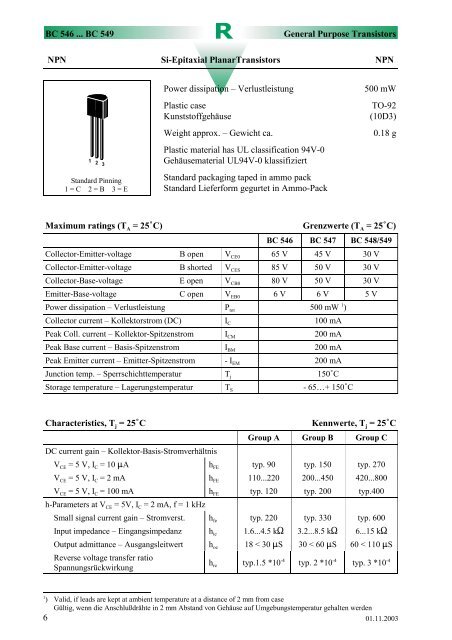
NPN Si-Epitaxial PlanarTransistors NPN<br />
Standard Pinning<br />
1 = C 2 = B 3 = E<br />
Power dissipation – Verlustleistung<br />
Plastic case<br />
Kunststoffgehäuse<br />
Weight approx. – Gewicht ca.<br />
Plastic material has UL classification 94V-0<br />
Gehäusematerial UL94V-0 klassifiziert<br />
Standard packaging taped in ammo pack<br />
Standard Lieferform gegurtet in Ammo-Pack<br />
500 mW<br />
TO-92<br />
(10D3)<br />
0.18 g<br />
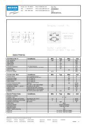
Maximum ratings (T A = 25C)<br />
Grenzwerte (T A = 25C)<br />
<strong>BC</strong> 546 <strong>BC</strong> 547 <strong>BC</strong> <strong>548</strong>/549<br />
Collector-Emitter-voltage B open V CE0 65 V 45 V 30 V<br />
Collector-Emitter-voltage B shorted V CES 85 V 50 V 30 V<br />
Collector-Base-voltage E open V CB0 80 V 50 V 30 V<br />
Emitter-Base-voltage C open V EB0 6 V 6 V 5 V<br />
Power dissipation – Verlustleistung P tot 500 mW 1 )<br />
Collector current – Kollektorstrom (DC) I C 100 mA<br />
Peak Coll. current – Kollektor-Spitzenstrom I CM 200 mA<br />
Peak Base current – Basis-Spitzenstrom I BM 200 mA<br />
Peak Emitter current – Emitter-Spitzenstrom - I EM 200 mA<br />
Junction temp. – Sperrschichttemperatur T j 150C<br />
Storage temperature – Lagerungstemperatur T S - 65…+ 150C<br />
Characteristics, T j = 25C<br />
Kennwerte, T j = 25C<br />
Group A Group B Group C<br />
DC current gain – Kollektor-Basis-Stromverhältnis<br />
V CE = 5 V, I C = 10 A h FE typ. 90 typ. 150 typ. 270<br />
V CE = 5 V, I C = 2 mA h FE 110...220 200...450 420...800<br />
V CE = 5 V, I C = 100 mA h FE typ. 120 typ. 200 typ.400<br />
h-Parameters at V CE = 5V, I C = 2 mA, f = 1 kHz<br />
Small signal current gain – Stromverst. h fe typ. 220 typ. 330 typ. 600<br />
Input impedance – Eingangsimpedanz h ie 1.6...4.5 k 3.2...8.5 k 6...15 k<br />
Output admittance – Ausgangsleitwert h oe 18 < 30 S 30 < 60 S 60 < 110 S<br />
Reverse voltage transfer ratio<br />
Spannungsrückwirkung<br />
h re typ.1.5 *10 -4 typ. 2 *10 -4 typ. 3 *10 -4<br />
1<br />
) Valid, if leads are kept at ambient temperature at a distance of 2 mm from case<br />
Gültig, wenn die Anschlußdrähte in 2 mm Abstand von Gehäuse auf Umgebungstemperatur gehalten werden<br />
6 01.11.2003
General Purpose Transistors <strong>BC</strong> 546 ... <strong>BC</strong> 549<br />
Characteristics, T j = 25C<br />
Collector saturation voltage – Kollektor-Sättigungsspannung<br />
Kennwerte, T j = 25C<br />
Min. Typ. Max.<br />
I C = 10 mA, I B = 0.5 mA V CEsat – 80 mV 200 mV<br />
I C = 100 mA, I B = 5 mA V CEsat – 200 mV 600 mV<br />
Base saturation voltage – Basis-Sättigungsspannung<br />
I C = 10 mA, I B = 0.5 mA V BEsat – 700 mV –<br />
I C = 100 mA, I B = 5 mA V BEsat – 900 mV –<br />
Base-Emitter voltage – Basis-Emitter-Spannung<br />
V CE = 5 V, I C = 2 mA V BE 580 mV 660 mV 700 mV<br />
V CE = 5 V, I C = 10 mA V BE – – 720 mV<br />
Collector-Emitter cutoff current – Kollektorreststrom<br />
V CE = 80 V <strong>BC</strong> 546 I CES – 0.2 nA 15 nA<br />
V CE = 50 V <strong>BC</strong> 547 I CES – 0.2 nA 15 nA<br />
V CE = 30 V <strong>BC</strong> <strong>548</strong> I CES – 0.2 nA 15 nA<br />
V CE = 30 V <strong>BC</strong> 549 I CES – 0.2 nA 15 nA<br />
Collector-Emitter cutoff current – Kollektorreststrom<br />
V CE = 80 V, T j = 125C <strong>BC</strong> 546 I CES – – 4 A<br />
V CE = 50 V, T j = 125C <strong>BC</strong> 547 I CES – – 4 A<br />
V CE = 30 V, T j = 125C <strong>BC</strong> <strong>548</strong> I CES – – 4 A<br />
V CE = 30 V, T j = 125C <strong>BC</strong> 549 I CES – – 4 A<br />
Gain-Bandwidth Product – Transitfrequenz<br />
V CE = 5 V, I C = 10 mA, f = 100 MHz f T – 300 MHz –<br />
Collector-Base Capacitance – Kollektor-Basis-Kapazität<br />
V CB = 10 V, f = 1 MHz C CB0 – 3.5 pF 6 pF<br />
Emitter-Base Capacitance – Emitter-Basis-Kapazität<br />
V EB = 0.5 V, f = 1 MHz C EB0 – 9 pF –<br />
Noise figure – Rauschmaß<br />
V CE = 5 V, I C = 200 A <strong>BC</strong> 547 F – 2 dB 10 dB<br />
R G = 2 k f = 1 kHz, <strong>BC</strong> <strong>548</strong> F – 1.2 dB 4 dB<br />
f = 200 Hz <strong>BC</strong> 549 F – 1.2 dB 4 dB<br />
Thermal resistance junction to ambient air<br />
Wärmewiderstand Sperrschicht – umgebende Luft<br />
Re<strong>com</strong>mended <strong>com</strong>plementary PNP transistors<br />
Empfohlene komplementäre PNP-Transistoren<br />
R thA 250 K/W 1 )<br />
<strong>BC</strong> 556 ... <strong>BC</strong> 559<br />
Available current gain groups per type<br />
Lieferbare Stromverstärkungsgruppen pro Typ<br />
<strong>BC</strong> 546A<br />
<strong>BC</strong> 547A<br />
<strong>BC</strong> <strong>548</strong>A<br />
<strong>BC</strong> 546B<br />
<strong>BC</strong> 547B<br />
<strong>BC</strong> <strong>548</strong>B<br />
<strong>BC</strong> 549B<br />
<strong>BC</strong> 547C<br />
<strong>BC</strong> <strong>548</strong>C<br />
<strong>BC</strong> 549C<br />
1<br />
) Valid, if leads are kept at ambient temperature at a distance of 2 mm from case<br />
Gültig, wenn die Anschlußdrähte in 2 mm Abstand von Gehäuse auf Umgebungstemperatur gehalten werden<br />
01.11.2003<br />
7