Bill of Materials: Recommended Tools: - APR
Bill of Materials: Recommended Tools: - APR
Bill of Materials: Recommended Tools: - APR

Create successful ePaper yourself
Turn your PDF publications into a flip-book with our unique Google optimized e-Paper software.
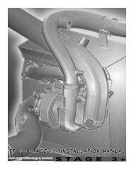
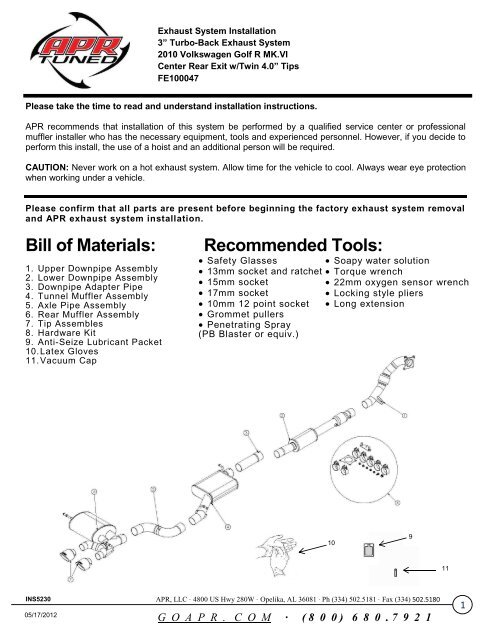
Exhaust System Installation<br />
3” Turbo-Back Exhaust System<br />
2010 Volkswagen Golf R MK.VI<br />
Center Rear Exit w/Twin 4.0” Tips<br />
FE100047<br />
Please take the time to read and understand installation instructions.<br />
<strong>APR</strong> recommends that installation <strong>of</strong> this system be performed by a qualified service center or pr<strong>of</strong>essional<br />
muffler installer who has the necessary equipment, tools and experienced personnel. However, if you decide to<br />
perform this install, the use <strong>of</strong> a hoist and an additional person will be required.<br />
CAUTION: Never work on a hot exhaust system. Allow time for the vehicle to cool. Always wear eye protection<br />
when working under a vehicle.<br />
Please confirm that all parts are present before beginning the factory exhaust system removal<br />
and <strong>APR</strong> exhaust system installation.<br />
<strong>Bill</strong> <strong>of</strong> <strong>Materials</strong>:<br />
1. Upper Downpipe Assembly<br />
2. Lower Downpipe Assembly<br />
3. Downpipe Adapter Pipe<br />
4. Tunnel Muffler Assembly<br />
5. Axle Pipe Assembly<br />
6. Rear Muffler Assembly<br />
7. Tip Assembles<br />
8. Hardware Kit<br />
9. Anti-Seize Lubricant Packet<br />
10. Latex Gloves<br />
11. Vacuum Cap<br />
<strong>Recommended</strong> <strong>Tools</strong>:<br />
Safety Glasses Soapy water solution<br />
13mm socket and ratchet Torque wrench<br />
15mm socket<br />
22mm oxygen sensor wrench<br />
17mm socket<br />
Locking style pliers<br />
10mm 12 point socket Long extension<br />
Grommet pullers<br />
Penetrating Spray<br />
(PB Blaster or equiv.)<br />
108<br />
9<br />
11<br />
INS5230 <strong>APR</strong>, LLC · 4800 US Hwy 280W · Opelika, AL 36081 · Ph (334) 502.5181 · Fax (334) 502.5180<br />
05/17/2012<br />
G O A P R . C O M · ( 8 0 0 ) 6 8 0 . 7 9 2 1<br />
1
Exhaust System Installation<br />
3” Turbo-Back Exhaust System<br />
2010 Volkswagen Golf R MK.VI<br />
Center Rear Exit w/Twin 4.0” Tips<br />
FE100047<br />
Removal <strong>of</strong> Stock System:<br />
The factory exhaust will be removed in two sections: the cat-back (rear) section first, followed by the downpipe<br />
(front) section.<br />
Catback Section<br />
1. Using a 13mm socket and ratchet, loosen both nuts on the factory cat-back to downpipe clamp.<br />
(SEE Fig. A)<br />
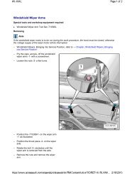
2. Using grommet pullers or a similar device, remove the hanger near the front <strong>of</strong> the catback section from<br />
the grommet. (SEE Fig. B)<br />
NOTE: The use <strong>of</strong> a soapy water solution may aid in the removal and later installation <strong>of</strong> the hangers in<br />
the rubber isolators.<br />
3. Remove the hanger near the middle <strong>of</strong> the factory cat-back section from the rubber isolator.<br />
(SEE Fig. C)<br />
4. Locate and remove the vacuum line attached to the factory muffler. (SEE Fig. D)<br />
5. Using a 13mm socket and a long extension, unbolt the left and right side hanger mounts from the vehicle<br />
by removing the two retaining bolts. (SEE Fig. E & F) Carefully slide the factory catback section back from<br />
the factory sleeve clamp and lower from the vehicle.<br />
6. With the factory rear section on the ground, remove the hanger mounts from the factory system. Set<br />
aside both the rear muffler hanger mounts and retaining bolts to be reused during the installation process.<br />
(SEE Fig. G & H) This completes the removal <strong>of</strong> the cat-back section.<br />
FIG. A FIG. B FIG. C FIG. D<br />
FIG.E FIG. F FIG. G FIG. H<br />
INS5230 <strong>APR</strong>, LLC · 4800 US Hwy 280W · Opelika, AL 36081 · Ph (334) 502.5181 · Fax (334) 502.5180<br />
05/17/2012<br />
G O A P R . C O M · ( 8 0 0 ) 6 8 0 . 7 9 2 1<br />
2
Exhaust System Installation<br />
3” Turbo-Back Exhaust System<br />
2010 Volkswagen Golf R MK.VI<br />
Center Rear Exit w/Twin 4.0” Tips<br />
FE100047<br />
Downpipe Section<br />
1. Open the hood and disconnect the negative terminal from the battery.<br />
2. Disconnect the MAF sensor plug near the top left side <strong>of</strong> the engine shroud, and remove the wire from the<br />
clip holding it to the shroud. (SEE Fig. I) Unclip the turbo intake pipe from the engine shroud, and<br />
separate the two pieces, being careful not to lose the O-ring gasket that is used to seal this connection.<br />
(SEE Fig J & K)<br />
3. Using a pair <strong>of</strong> locking pliers (i.e. channel locks) or a similar device, unclip the air snorkel from the engine<br />
shroud. (SEE Fig. L)<br />
4. Remove the hose on the left side <strong>of</strong> the engine shroud from the retaining clips that are attached to the<br />
engine shroud. (SEE Fig. M)<br />
5. Remove the engine shroud by pulling upwards to free it from the four retaining studs. (SEE Fig. N)<br />
6. Unplug the upper downpipe oxygen sensor connector near the brake master cylinder on the left side <strong>of</strong> the<br />
vehicle, and remove the wire from the clip anchoring it to the firewall. (SEE Fig. O)<br />
7. Using a 22mm oxygen sensor wrench, remove the upper downpipe oxygen sensor from the factory<br />
downpipe (SEE Fig. P). Note: breaking the sensor loose from the factory downpipe may be easier from<br />
the underside <strong>of</strong> the vehicle.<br />
Warning: Be careful to not contaminate the sensor end <strong>of</strong> the oxygen sensors with dirt, grease, etc as it<br />
may prevent them from functioning properly.<br />
FIG.I FIG. J FIG. K FIG. L<br />
FIG.M FIG. N FIG.O FIG. P<br />
INS5230 <strong>APR</strong>, LLC · 4800 US Hwy 280W · Opelika, AL 36081 · Ph (334) 502.5181 · Fax (334) 502.5180<br />
05/17/2012<br />
G O A P R . C O M · ( 8 0 0 ) 6 8 0 . 7 9 2 1<br />
3
Exhaust System Installation<br />
3” Turbo-Back Exhaust System<br />
2010 Volkswagen Golf R MK.VI<br />
Center Rear Exit w/Twin 4.0” Tips<br />
FE100047<br />
8. Spray the downpipe flange mounting nuts with PB Blaster or an equivalent rust penetrating spray. Allow<br />
product to soak in per product recommendations. Then remove the two upper downpipe flange nuts using<br />
a 17mm sockets and ratchet. (SEE Fig. Q)<br />
9. Use the 22mm oxygen sensor wrench to remove the oxygen sensor(s) for the lower section <strong>of</strong> the<br />
downpipe. The sensor(s) are located in the tunnel underneath the vehicle near the factory catalytic<br />
converter. (SEE Fig. R)<br />
10. Using a 13mm socket and ratchet with an extension, remove the two bolts holding the driveshaft carrier in<br />
place. (SEE Fig S) Temporarily support the driveshaft in the center <strong>of</strong> the vehicle.<br />
11. Using a 10mm 12-point socket and ratchet with an extension, remove the bolts connecting the driveshaft<br />
to the differential. (SEE Fig. T) Move the driveshaft towards the right <strong>of</strong> the vehicle to allow clearance for<br />
removal <strong>of</strong> the factory downpipe. (SEE Fig. U) You will need to pull the driveshaft towards the rear <strong>of</strong> the<br />
vehicle while moving it to the right in order to free the driveshaft from the transfer case.<br />
12. Using a 17mm socket and ratchet, remove the two lower downpipe flange nuts. (SEE Fig. V)<br />
13. Remove the oxygen sensor heat shield from the turbo flange studs. Make sure to note the orientation <strong>of</strong><br />
the heat shield for proper re-installation later on. (SEE Fig. W)<br />
14. Unbolt the downpipe grommet bracket from the vehicle by removing the two<br />
bolts with a 13mm socket and ratchet. (SEE Fig. X)<br />
15. Using a 13mm socket and ratchet, remove the retaining bolts holding the cross<br />
brace in the tunnel near the end <strong>of</strong> the factory downpipe. (SEE Fig. Y) Use<br />
caution as the factory downpipe will droop after removing the tunnel cross brace.<br />
16. Remove the downpipe from the vehicle by sliding the mounting flange <strong>of</strong>f <strong>of</strong> the<br />
studs coming from the turbo. Remove the downpipe grommet bracket from the<br />
factory downpipe hangers. This completes the removal <strong>of</strong> the downpipe section. FIG.Q<br />
FIG.R FIG. S FIG. T FIG. U<br />
FIG.V FIG. W FIG. X FIG. Y<br />
INS5230 <strong>APR</strong>, LLC · 4800 US Hwy 280W · Opelika, AL 36081 · Ph (334) 502.5181 · Fax (334) 502.5180<br />
05/17/2012<br />
G O A P R . C O M · ( 8 0 0 ) 6 8 0 . 7 9 2 1<br />
4
Exhaust System Installation<br />
3” Turbo-Back Exhaust System<br />
2010 Volkswagen Golf R MK.VI<br />
Center Rear Exit w/Twin 4.0” Tips<br />
FE100047<br />
Installation <strong>of</strong> <strong>APR</strong> Exhaust System:<br />
NOTE: Apply the anti-seize lubricant (supplied) to the threads ONLY <strong>of</strong> all the<br />
clamps and flange bolts. Failure to follow this procedure can cause nuts to seize<br />
on clamps and potentially destroy threads. After applying anti-seize lubricant,<br />
be sure to thoroughly clean hands as lubricant will tarnish stainless steel.<br />
Align all clamps so that the center <strong>of</strong> the clamp bolt is 90 degrees from the notch on<br />
the pipe (SEE Fig. A)<br />
NOTE: All clamps should be tightened using a properly calibrated Torque<br />
Wrench. Using an air impact gun will damage the clamp and reduce its ability to<br />
effectively seal the joint. It may also cause the joint to separate thereby causing<br />
damage to your exhaust system and your vehicle.<br />
FIG.A<br />
1. Remove all exhaust system components for the shipping carton, including the<br />
five 3.0” clamps, the two 2.5” clamps, the M10 flange bolt, the five M10 flange<br />
nuts, the M18 oxygen sensor port block <strong>of</strong>f bolt, and the downpipe flange gasket.<br />
2. Locate the <strong>APR</strong> upper downpipe assembly, four <strong>of</strong> the M10 flange nuts, and the<br />
downpipe flange gasket. Place the new OEM downpipe flange gasket over the FIG.B<br />
studs coming out <strong>of</strong> the turbo. (SEE Fig. B) Then slide the mounting flange <strong>of</strong><br />
the upper downpipe assembly over the mounting studs.<br />
3. Re-install the factory oxygen sensor heat shield that was removed during<br />
removal <strong>of</strong> the factory downpipe onto the mounting studs paying attention to<br />
correct orientation. (SEE Fig. C)<br />
4. Hand thread on the four M10 flange nuts. Tighten the two lower downpipe flange<br />
mounting nuts using a 15mm socket and ratchet. (SEE Fig. D)<br />
5. Tighten the two upper downpipe flange mounting nuts with the 15mm socket and<br />
FIG.C<br />
ratchet. (SEE Fig. E). Torque all flange mounting nuts to 22 ft-lbs (30 N-m).<br />
6. Install the upper downpipe oxygen sensor and tighten with the 22mm oxygen sensor<br />
wrench (SEE Fig F). Reconnect the oxygen sensor connector to the plug near the brake<br />
master cylinder, and anchor the wire with the retaining clip on the firewall. (SEE Fig. G).<br />
FIG.D FIG. E FIG. F FIG. G<br />
INS5230 <strong>APR</strong>, LLC · 4800 US Hwy 280W · Opelika, AL 36081 · Ph (334) 502.5181 · Fax (334) 502.5180<br />
05/17/2012<br />
G O A P R . C O M · ( 8 0 0 ) 6 8 0 . 7 9 2 1<br />
5
Exhaust System Installation<br />
3” Turbo-Back Exhaust System<br />
2010 Volkswagen Golf R MK.VI<br />
Center Rear Exit w/Twin 4.0” Tips<br />
FE100047<br />
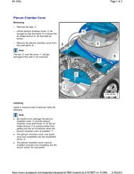
7. Re-install the engine shroud by aligning it with the mounting studs and pushing<br />
it firmly onto the engine. Reconnect all factory hoses and connectors as they<br />
were removed, making sure all clips, o-rings, and harnesses are positioned<br />
and oriented correctly. (SEE Fig. H, I, J & K)<br />
8. Locate the <strong>APR</strong> downpipe hanger assembly and the factory downpipe<br />
grommet bracket. Push the hanger assembly studs into the grommet bracket,<br />
and re-install the grommet bracket onto the vehicle. Tighten the bolts to 18 ftlbs<br />
(24N-m). (SEE Fig. L)<br />
9. Locate the remaining M10 flange nut and the M10 x 20mm long bolt. With the FIG. H<br />
center hole aligned with the slotted hole on the upper downpipe mounting tab.<br />
Install the M10 bolt through these holes from the engine side, and secure with<br />
the M10 flange nut. Snugly tighten with a 15mm socket and ratchet.<br />
(SEE Fig. M)<br />
10. Re-install the driveshaft and torque all bolts to factory specifications. (SEE<br />
Fig. N & O)<br />
11. Locate the <strong>APR</strong> lower downpipe assembly and one <strong>of</strong> the 3” clamps. Properly<br />
align the clamp on the catalytic converter side <strong>of</strong> the lower downpipe, and slide<br />
the lower downpipe intlet over the end <strong>of</strong> the upper downpipe assembly. Check FIG. I<br />
the orientation <strong>of</strong> the lower downpipe, so that the oxygen sensor bungs are oriented<br />
toward the passenger side <strong>of</strong> the vehicle and level with the vehicle. The outlet pipe coming out <strong>of</strong> the<br />
tunnel resonator should only <strong>of</strong>fset upward in the vehicle with no side-to-side <strong>of</strong>fset. Snugly tighten the<br />
clamp to retain the lower downpipe section. (SEE Fig. P & Q)<br />
FIG. J FIG. K FIG. L FIG. M<br />
FIG.N FIG. O FIG. P FIG. Q<br />
INS5230 <strong>APR</strong>, LLC · 4800 US Hwy 280W · Opelika, AL 36081 · Ph (334) 502.5181 · Fax (334) 502.5180<br />
05/17/2012<br />
G O A P R . C O M · ( 8 0 0 ) 6 8 0 . 7 9 2 1<br />
6
Exhaust System Installation<br />
3” Turbo-Back Exhaust System<br />
2010 Volkswagen Golf R MK.VI<br />
Center Rear Exit w/Twin 4.0” Tips<br />
FE100047<br />
12. Install the downpipe oxygen sensor in the bung corresponding to the vehicle<br />
factory exhaust using a 22mm oxygen sensor wrench. Make sure that the<br />
oxygen sensor wire has some slack to prevent damage to it. Install the oxygen<br />
sensor block <strong>of</strong>f bolt (supplied) in the extra oxygen sensor bung. (SEE Fig. R&S)<br />
13. Locate the <strong>APR</strong> downpipe adapter pipe and a 3” clamp. Properly align the clamp<br />
on the expanded side <strong>of</strong> the adapter pipe and slide the expanded side <strong>of</strong> the<br />
adapter pipe onto the outlet pipe <strong>of</strong> the lower downpipe assembly. Snugly tighten<br />
the 3” clamp to retain the adapter pipe. (SEE Fig. T)<br />
FIG. R<br />
14. Locate the <strong>APR</strong> tunnel muffler assembly and a 3” clamp. Properly align the clamp<br />
on the expanded inlet <strong>of</strong> the tunnel muffler assembly and slide the inlet <strong>of</strong> the<br />
tunnel muffler onto the outlet <strong>of</strong> the downpipe adapter pipe. Insert the hangers on<br />
the tunnel muffler assembly into the factory rubber grommets. A soapy water<br />
solution will aid in the installation process <strong>of</strong> the hangers. Snugly tighten the 3”<br />
clamp to retain the tunnel muffler section. (SEE Fig. U, V&W)<br />
15. Reinstall the factory tunnel crossbrace and tighten using a 13mm socket and<br />
ratchet. Torque nuts to factory specifications. (SEE Fig. X)<br />
16. Locate the <strong>APR</strong> axle pipe and a 3” clamp. Properly align the clamp on the<br />
FIG. S<br />
expanded inlet <strong>of</strong> the axle pipe and slide the axle pipe onto the outlet <strong>of</strong> the tunnel<br />
muffler assembly. Align the axle pipe so that the outlet is centered in the vehicle and has proper<br />
clearance to all frame and suspension components. Snugly tighten the 3” clamp. (SEE Fig. Y&Z)<br />
17. Locate the factory hanger mounting brackets that were removed earlier during the removal <strong>of</strong> the factory<br />
cat-back exhaust. Using a 13mm socket and ratchet, reinstall the factory hangers onto the vehicle paying<br />
attention to correct orientation <strong>of</strong> the hanger brackets. Hanger brackets should be oriented identical to<br />
stock. Leave the bolts slightly loose at this time.<br />
FIG.T FIG. U FIG. V FIG. W<br />
FIG. X FIG. Y FIG. Z<br />
INS5230 <strong>APR</strong>, LLC · 4800 US Hwy 280W · Opelika, AL 36081 · Ph (334) 502.5181 · Fax (334) 502.5180<br />
05/17/2012<br />
G O A P R . C O M · ( 8 0 0 ) 6 8 0 . 7 9 2 1<br />
7
Exhaust System Installation<br />
3” Turbo-Back Exhaust System<br />
2010 Volkswagen Golf R MK.VI<br />
Center Rear Exit w/Twin 4.0” Tips<br />
FE100047<br />
18. Locate the supplied vacuum cap and cap the vacuum line that was<br />
connected to the factory rear muffler. (SEE Fig. AA) Feed as much <strong>of</strong> the<br />
vacuum line into the bumber as possible and tuck away for clearance to the<br />
<strong>APR</strong> exhaust.<br />
19. Locate a 3” clamp and properly align it on the expanded inlet <strong>of</strong> the rear<br />
muffler assembly. Slide the inlet <strong>of</strong> the rear muffler assembly onto the outlet<br />
<strong>of</strong> the axle pipe. Install the rear muffler hangers into the factory grommets.<br />
(SEE Fig. BB, CC & DD)<br />
20. Align the muffler outlets so that they are centered in the tip openings in the rear FIG. AA<br />
fascia. Snugly tighten the muffler clamp and factory hanger bracket bolts at this time.<br />
21. Locate the <strong>APR</strong> tip assemblies and the two 2.5” clamps. Properly align the clamp<br />
on the tip assembly inlet and slide the tips onto the muffler outlet pipes. Both clamps should be oriented<br />
so that the bolt is on top and pointing toward the passenger side <strong>of</strong> the vehicle. Installing the driver side<br />
tip first and loosely tightening the clamp, followed by installing the passenger side tip and loosely tighten<br />
the clamp will make the installation easier. There are multiple access points in the fascia & bumper that<br />
will allow the use <strong>of</strong> various extensions to tighten the tip clamps. (SEE Fig. EE)<br />
22. Align the tips so that they are centered, rotated square to the vehicle, and even depth with each other.<br />
Loosely snug the tip clamps at this time.<br />
23. Visually inspect the exhaust system position, tip alignment, clamp orientation, and all exhaust system<br />
clearances. Make any necessary adjustments at the slip joints and at the front downpipe bracket.<br />
24. When the exhaust system is in the desired location, tighten the nuts on the clamps. Torque nuts to 45 ftlbs<br />
(61 N-m). Tighten the M10 nut and bolt at the front downpipe hanger assembly to 22 ft-lbs (30 N-m).<br />
25. Reconnect the negative battery terminal. Let the car sit for at least three minutes with the ignition key on<br />
and engine <strong>of</strong>f. Close the hood. This completes the installation <strong>of</strong> the <strong>APR</strong> system.<br />
26. It is STRONGLY SUGGESTED that all clamps be checked and re-tightened (if necessary) to the<br />
recommended torque after initial road testing <strong>of</strong> the vehicle, as thermal cycling has occurred on the<br />
system. Wait until the system has fully cooled to perform this step.<br />
FIG. BB FIG. CC FIG. DD FIG. EE<br />
NOTE: During cold weather start-ups, you may experience an exhaust sound that is deeper and louder in tone than usual.<br />
This is temporary and will diminish to normal levels once your engine has reached its normal operating temperature.<br />
NOTE: Immediately following the installation <strong>of</strong> your exhaust system, you may experience a trace <strong>of</strong> smoke after initial startup.<br />
DO NOT be alarmed. The smoke is caused by the burning <strong>of</strong> a small amount <strong>of</strong> forming oil residue used in the<br />
manufacturing process.<br />
INS5230 <strong>APR</strong>, LLC · 4800 US Hwy 280W · Opelika, AL 36081 · Ph (334) 502.5181 · Fax (334) 502.5180<br />
05/17/2012<br />
G O A P R . C O M · ( 8 0 0 ) 6 8 0 . 7 9 2 1<br />
8