
You also want an ePaper? Increase the reach of your titles
YUMPU automatically turns print PDFs into web optimized ePapers that Google loves.
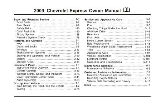
2009 Chevrolet Express Owner Manual M<br />
Seats and Restraint System ............................. 1-1<br />
Front Seats ............................................... 1-2<br />
Rear Seats ............................................... 1-6<br />
Safety Belts ............................................. 1-10<br />
Child Restraints ....................................... 1-30<br />
Airbag System ......................................... 1-58<br />
Restraint System Check ............................ 1-78<br />
Features and Controls ..................................... 2-1<br />
Keys ........................................................ 2-2<br />
Doors and Locks ....................................... 2-6<br />
Windows ................................................. 2-13<br />
Theft-Deterrent Systems ............................ 2-16<br />
Starting and Operating Your Vehicle ........... 2-19<br />
Mirrors .................................................... 2-32<br />
Storage Areas ......................................... 2-34<br />
Instrument Panel ............................................. 3-1<br />
Instrument Panel Overview .......................... 3-4<br />
Climate Controls ...................................... 3-19<br />
Warning Lights, Gages, and Indicators ........ 3-23<br />
Driver Information Center (DIC) .................. 3-41<br />
Audio System(s) ....................................... 3-63<br />
Driving Your Vehicle ....................................... 4-1<br />
Your Driving, the Road, and the Vehicle ....... 4-2<br />
Towing ................................................... 4-25<br />
Service and Appearance Care .......................... 5-1<br />
Service ..................................................... 5-3<br />
Fuel ......................................................... 5-5<br />
Checking Things Under the Hood ............... 5-12<br />
All-Wheel Drive ........................................ 5-44<br />
Rear Axle ............................................... 5-45<br />
Front Axle ............................................... 5-46<br />
Noise Control System ............................... 5-47<br />
Bulb Replacement .................................... 5-48<br />
Windshield Wiper Blade Replacement ......... 5-53<br />
Tires ...................................................... 5-54<br />
Appearance Care ..................................... 5-97<br />
Vehicle Identification ............................... 5-104<br />
Electrical System .................................... 5-105<br />
Capacities and Specifications ................... 5-111<br />
Maintenance Schedule ..................................... 6-1<br />
Maintenance Schedule ................................ 6-2<br />
Customer Assistance Information .................... 7-1<br />
Customer Assistance and Information ........... 7-2<br />
Reporting Safety Defects ........................... 7-15<br />
Vehicle Data Recording and Privacy ........... 7-18<br />
Index ................................................................ 1
Read this manual from beginning to end to learn about<br />
the vehicle’s features and controls. Pictures, symbols,<br />
and words work together to explain vehicle operation.<br />
Keep this manual in the vehicle for quick reference.<br />
Canadian Owners<br />
GENERAL MOTORS, <strong>GM</strong>, the <strong>GM</strong> Emblem,<br />
CHEVROLET, the CHEVROLET Emblem, and the<br />
name CHEVY EXPRESS are registered trademarks of<br />
General Motors Corporation.<br />
This manual includes the latest information at the time it<br />
was printed. <strong>GM</strong> reserves the right to make changes after<br />
that time without further notice. For vehicles first sold in<br />
<strong>Canada</strong>, substitute the name “General Motors of <strong>Canada</strong><br />
Limited” for Chevrolet Motor Division wherever it appears<br />
in this manual.<br />
This manual describes features that may or may not be<br />
on your specific vehicle.<br />
If the vehicle has the DURAMAX ® Diesel engine, refer<br />
to the DURAMAX ® Diesel supplement for additional<br />
and specific information on this engine.<br />
A French language copy of this manual can be obtained<br />
from your dealer/retailer or from:<br />
Helm, Incorporated<br />
P.O. Box 07130<br />
Detroit, MI 48207<br />
1-800-551-4123<br />
helminc.com<br />
Propriétaires Canadiens<br />
On peut obtenir un exemplaire de ce guide en français<br />
auprès de concessionnaire ou à l’adresse suivante:<br />
Helm Incorporated<br />
P.O. Box 07130<br />
Detroit, MI 48207<br />
1-800-551-4123<br />
helminc.com<br />
Litho in U.S.A.<br />
Part No. 25780708 A First Printing<br />
© 2008 General Motors Corporation. All Rights Reserved.<br />
ii
Index<br />
To quickly locate information about the vehicle use the<br />
Index in the back of the manual. It is an alphabetical<br />
list of what is in the manual and the page number where<br />
it can be found.<br />
Safety Warnings and Symbols<br />
A circle with a slash<br />
through it is a safety<br />
symbol which means<br />
“Do Not,” “Do not do this” or<br />
“Do not let this happen.”<br />
A box with the word CAUTION is used to tell about<br />
things that could hurt you or others if you were to ignore<br />
the warning.<br />
{ CAUTION:<br />
These mean there is something that could hurt<br />
you or other people.<br />
Cautions tell what the hazard is and what to do to avoid<br />
or reduce the hazard. Read these <strong>caution</strong>s.<br />
A notice tells about something that can damage the<br />
vehicle.<br />
Notice: These mean there is something that could<br />
damage your vehicle.<br />
Many times, this damage would not be covered by the<br />
vehicle’s warranty, and it could be costly. The notice<br />
tells what to do to help avoid the damage.<br />
There are also warning labels on the vehicle which use<br />
the same words, CAUTION or Notice.<br />
iii
Vehicle Symbols<br />
The vehicle has components and labels that use<br />
symbols instead of text. Symbols are shown along with<br />
the text describing the operation or information<br />
relating to a specific component, control, message,<br />
gage, or indicator.<br />
M : This symbol is shown when you need to see your<br />
owner manual for additional instructions or information.<br />
* : This symbol is shown when you need to see a<br />
service manual for additional instructions or information.<br />
Vehicle Symbol Chart<br />
Here are some additional symbols that may be found on<br />
the vehicle and what they mean. For more information<br />
on the symbol, refer to the index.<br />
9 : Airbag Readiness Light<br />
# : Air Conditioning<br />
! : Antilock Brake System (ABS)<br />
g : Audio Steering Wheel Controls or OnStar ®<br />
$ : Brake System Warning Light<br />
" : Charging System<br />
I : Cruise Control<br />
B : Engine Coolant Temperature<br />
O : Exterior Lamps<br />
# : Fog Lamps<br />
. : Fuel Gage<br />
+ : Fuses<br />
i : Headlamp High/Low-Beam Changer<br />
j : LATCH System Child Restraints<br />
* : Malfunction Indicator Lamp<br />
: : Oil Pressure<br />
} : Power<br />
/ : Remote Vehicle Start<br />
> : Safety Belt Reminders<br />
7 : Tire Pressure Monitor<br />
_ : Tow/Haul Mode<br />
F : Traction Control<br />
M : Windshield Washer Fluid<br />
iv
Section 1<br />
Seats and Restraint System<br />
Front Seats ......................................................1-2<br />
Manual Seats ................................................1-2<br />
Power Seat ...................................................1-3<br />
Reclining Seatbacks ........................................1-3<br />
Rear Seats .......................................................1-6<br />
Rear Seat Operation .......................................1-6<br />
Safety Belts ...................................................1-10<br />
Safety Belts: They Are for Everyone ................1-10<br />
How to Wear Safety Belts Properly .................1-15<br />
Lap-Shoulder Belt .........................................1-24<br />
Safety Belt Use During Pregnancy ..................1-29<br />
Safety Belt Extender .....................................1-30<br />
Child Restraints .............................................1-30<br />
Older Children ..............................................1-30<br />
Infants and Young Children ............................1-33<br />
Child Restraint Systems .................................1-37<br />
Where to Put the Restraint .............................1-39<br />
Lower Anchors and Tethers for Children<br />
(LATCH) ..................................................1-41<br />
Securing a Child Restraint in a Rear Seat<br />
Position ...................................................1-48<br />
Securing a Child Restraint in the Right Front<br />
Seat Position (With Passenger Sensing<br />
System) ...................................................1-50<br />
Securing a Child Restraint in the Right Front<br />
Seat Position (With Airbag On-Off Switch) .....1-54<br />
Airbag System ...............................................1-58<br />
Where Are the Airbags? ................................1-60<br />
When Should an Airbag Inflate? .....................1-63<br />
What Makes an Airbag Inflate? .......................1-64<br />
How Does an Airbag Restrain? .......................1-65<br />
What Will You See After an Airbag Inflates? .....1-65<br />
Airbag Off Switch ..........................................1-67<br />
Passenger Sensing System ............................1-70<br />
Servicing Your Airbag-Equipped Vehicle ...........1-76<br />
Adding Equipment to Your Airbag-Equipped<br />
Vehicle ....................................................1-76<br />
Restraint System Check ..................................1-78<br />
Checking the Restraint Systems ......................1-78<br />
Replacing Restraint System Parts After<br />
a Crash ...................................................1-79<br />
1-1
Front Seats<br />
Manual Seats<br />
{ CAUTION:<br />
If the vehicle has a manual seat, it can be moved<br />
forward or rearward.<br />
1. Lift the bar to unlock<br />
the seat.<br />
2. Slide the seat to the<br />
desired position and<br />
release the bar.<br />
You can lose control of the vehicle if you try to<br />
adjust a manual driver’s seat while the vehicle is<br />
moving. The sudden movement could startle and<br />
confuse you, or make you push a pedal when you<br />
do not want to. Adjust the driver’s seat only when<br />
the vehicle is not moving.<br />
Try to move the seat with your body to be sure the seat<br />
is locked in place.<br />
1-2
Power Seat<br />
Reclining Seatbacks<br />
{ CAUTION:<br />
You can lose control of the vehicle if you try to<br />
adjust a manual driver’s seat while the vehicle is<br />
moving. The sudden movement could startle and<br />
confuse you, or make you push a pedal when you<br />
do not want to. Adjust the driver’s seat only when<br />
the vehicle is not moving.<br />
If the vehicle has front power seat(s), the controls are<br />
located at the front center of the seat cushion.<br />
To raise or lower the seat, move the center knob up or<br />
down. To move the seat forward or rearward, move<br />
the center knob toward the right or left.<br />
To raise or lower the front of the seat cushion, move the<br />
right lever up or down. To raise or lower the rear of<br />
the seat cushion, move the left lever up or down.<br />
{ CAUTION:<br />
If the seatback is not locked, it could move<br />
forward in a sudden stop or crash. That could<br />
cause injury to the person sitting there. Always<br />
push and pull on the seatback to be sure it is<br />
locked.<br />
The seats have manual reclining seatbacks. The lever<br />
used to operate them is located on the inboard side<br />
of the seats.<br />
1-3
To return the seatback to an upright position:<br />
1. Lift the lever fully without applying pressure to the<br />
seatback and the seatback will return to the upright<br />
position.<br />
2. Push and pull on the seatback to make sure it is<br />
locked.<br />
To recline the seatback:<br />
1. Lift the recline lever.<br />
2. Move the seatback to the desired position, then<br />
release the lever to lock the seatback in place.<br />
3. Push and pull on the seatback to make sure it is<br />
locked.<br />
1-4
{ CAUTION:<br />
CAUTION:<br />
(Continued)<br />
Sitting in a reclined position when the vehicle is in<br />
motion can be dangerous. Even if when buckled<br />
up, the safety belts cannot do their job when<br />
reclined like this.<br />
The shoulder belt cannot do its job because it will<br />
not be against your body. Instead, it will be in front<br />
of you. In a crash, you could go into it, receiving<br />
neck or other injuries.<br />
CAUTION: (Continued)<br />
The lap belt cannot do its job either. In a crash,<br />
the belt could go up over your abdomen. The belt<br />
forces would be there, not at your pelvic bones.<br />
This could cause serious internal injuries.<br />
For proper protection when the vehicle is in<br />
motion, have the seatback upright. Then sit well<br />
back in the seat and wear the safety belt properly.<br />
Do not have a seatback reclined if the vehicle is<br />
moving.<br />
1-5
Rear Seats<br />
Rear Seat Operation<br />
Removing the Rear Seat<br />
Disconnect the quick release latch plates for the<br />
lap-shoulder belts on the bench seat to be removed.<br />
1. To do this, press the<br />
tip of a key into the<br />
release hole of<br />
the safety belt buckle<br />
while pulling up on<br />
the safety belt.<br />
Three Passenger Seat Shown<br />
The driver side pin has a gray cap with a black “L”<br />
marked on it.<br />
2. Locate the pins.<br />
On a three passenger seat there are two pins<br />
located on the inboard sides of the rear seats.<br />
1-6
3. Pull the pin handle up to disengage the pin from<br />
the retaining clip, then pull the pin out.<br />
4. Repeat this procedure for the other pins.<br />
5. Pull the seat rearward about 2 inches (5 cm) and<br />
then lift the seat from the floor rails.<br />
6. Remove the seat from the vehicle.<br />
7. For the first row rear<br />
seat, stow the safety<br />
belt latch by attaching<br />
the clip on the safety<br />
belt latch to the trim just<br />
inside the side door.<br />
Three Passenger Seat Shown<br />
The passenger side pin has a black cap with a<br />
white “R” marked on it.<br />
On a four passenger seat, each half of the seat has a<br />
set of pins. The driver side has a set marked “L”, and<br />
the passenger side has a set marked “R”.<br />
If the vehicle has floor mats, the pins will be located<br />
under a flap that has been cut into the mat.<br />
For the remaining rear seats, stow the safety belt<br />
latch plate on the clip at the window trim.<br />
1-7
Replacing the Rear Seats<br />
CAUTION:<br />
(Continued)<br />
{ CAUTION:<br />
A seat that is not locked into place properly can<br />
move around in a collision or sudden stop. People<br />
in the vehicle could be injured. Be sure to lock the<br />
seat into place properly when installing it.<br />
{ CAUTION:<br />
A safety belt that is improperly routed, not properly<br />
attached, or twisted will not provide the protection<br />
needed in a crash. The person wearing the belt<br />
could be seriously injured. After raising the rear<br />
CAUTION: (Continued)<br />
seatback, always check to be sure that the safety<br />
belts are properly routed and attached, and are<br />
not twisted.<br />
1. Position the seat into the open slots in both rails.<br />
Push the seat forward in the rail, hooking both<br />
seat bases onto the pins inside of the rails.<br />
2. Locate the hole in the rail to install the locking pins at<br />
the rear of the seat base. If the vehicle has floor<br />
mats, pull the flap that has been cut into the mat.<br />
3. Insert the locking pins into the seat base and push<br />
the seat to line up the pins with the base.<br />
On a three passenger seat, the pin with the black<br />
cap marked “R” must be installed on the passenger<br />
side and the pin with the gray cap marked “L” on<br />
the driver side.<br />
On a four passenger seat, the pins marked “R”<br />
must be installed on the half of the seat on<br />
the passenger side. The pins marked “L” must be<br />
installed on the half of the seat on the driver side.<br />
1-8
Three Passenger Seat Shown<br />
4. Push the pin(s) marked “R” down until they are in<br />
the retaining clip.<br />
Three Passenger Seat Shown<br />
5. Push the pin(s) marked “L” down until they are in<br />
the retaining clip.<br />
6. If the vehicle has a floor mat, put the flap back to<br />
its original position.<br />
7. Repeat this procedure for the other seat base.<br />
8. Connect the quick-release latch plates for the<br />
lap-shoulder belts by inserting the latch plates<br />
into the buckles attached at the outboard positions<br />
of the bench seat. Do not twist the belt.<br />
9. Check that all locking pins are locked into place<br />
before operating the vehicle.<br />
1-9
Safety Belts<br />
Safety Belts: They Are for Everyone<br />
This section of the manual describes how to use<br />
safety belts properly. It also describes some things not<br />
to do with safety belts.<br />
{ CAUTION:<br />
Do not let anyone ride where a safety belt cannot<br />
be worn properly. In a crash, if you or your<br />
passenger(s) are not wearing safety belts, the<br />
injuries can be much worse. You can hit things<br />
inside the vehicle harder or be ejected from the<br />
vehicle. You and your passenger(s) can be<br />
seriously injured or killed. In the same crash, you<br />
might not be, if you are buckled up. Always fasten<br />
your safety belt, and check that your passenger(s)<br />
are restrained properly too.<br />
{ CAUTION:<br />
It is extremely dangerous to ride in a cargo area,<br />
inside or outside of a vehicle. In a collision, people<br />
riding in these areas are more likely to be<br />
seriously injured or killed. Do not allow people<br />
to ride in any area of your vehicle that is not<br />
equipped with seats and safety belts. Be sure<br />
everyone in your vehicle is in a seat and using a<br />
safety belt properly.<br />
This vehicle has indicators as a reminder to buckle the<br />
safety belts. See Safety Belt Reminders on page 3-26<br />
for additional information.<br />
1-10
In most states and in all Canadian provinces, the law<br />
requires wearing safety belts. Here is why:<br />
You never know if you will be in a crash. If you do have<br />
a crash, you do not know if it will be a serious one.<br />
A few crashes are mild, and some crashes can be so<br />
serious that even buckled up, a person would not<br />
survive. But most crashes are in between. In many of<br />
them, people who buckle up can survive and sometimes<br />
walk away. Without safety belts, they could have<br />
been badly hurt or killed.<br />
After more than 40 years of safety belts in vehicles,<br />
the facts are clear. In most crashes buckling up does<br />
matter... a lot!<br />
Why Safety Belts Work<br />
When you ride in or on anything, you go as fast as<br />
it goes.<br />
Take the simplest vehicle. Suppose it is just a seat on<br />
wheels.<br />
1-11
Put someone on it.<br />
Get it up to speed. Then stop the vehicle. The rider<br />
does not stop.<br />
1-12
The person keeps going until stopped by something.<br />
In a real vehicle, it could be the windshield...<br />
or the instrument panel...<br />
1-13
Questions and Answers About Safety<br />
Belts<br />
Q: Will I be trapped in the vehicle after a crash if I<br />
am wearing a safety belt?<br />
A: You could be — whether you are wearing a safety<br />
belt or not. But your chance of being conscious<br />
during and after an accident, so you can unbuckle<br />
and get out, is much greater if you are belted.<br />
And you can unbuckle a safety belt, even if you<br />
are upside down.<br />
or the safety belts!<br />
With safety belts, you slow down as the vehicle does.<br />
You get more time to stop. You stop over more distance,<br />
and your strongest bones take the forces. That is why<br />
safety belts make such good sense.<br />
1-14
Q: If my vehicle has airbags, why should I have to<br />
wear safety belts?<br />
A: Airbags are supplemental systems only; so they<br />
work with safety belts — not instead of them.<br />
Whether or not an airbag is provided, all occupants<br />
still have to buckle up to get the most protection.<br />
That is true not only in frontal collisions, but<br />
especially in side and other collisions.<br />
Q: If I am a good driver, and I never drive far from<br />
home, why should I wear safety belts?<br />
A: You may be an excellent driver, but if you are in a<br />
crash — even one that is not your fault — you and<br />
your passenger(s) can be hurt. Being a good<br />
driver does not protect you from things beyond<br />
your control, such as bad drivers.<br />
Most accidents occur within 25 miles (40 km)<br />
of home. And the greatest number of serious<br />
injuries and deaths occur at speeds of less than<br />
40 mph (65 km/h).<br />
Safety belts are for everyone.<br />
How to Wear Safety Belts Properly<br />
This section is only for people of adult size.<br />
Be aware that there are special things to know about<br />
safety belts and children. And there are different<br />
rules for smaller children and infants. If a child will be<br />
riding in the vehicle, see Older Children on page 1-30<br />
or Infants and Young Children on page 1-33. Follow<br />
those rules for everyone’s protection.<br />
It is very important for all occupants to buckle up.<br />
Statistics show that unbelted people are hurt more often<br />
in crashes than those who are wearing safety belts.<br />
Occupants who are not buckled up can be thrown out of<br />
the vehicle in a crash. And they can strike others in<br />
the vehicle who are wearing safety belts.<br />
First, before you or your passenger(s) wear a safety<br />
belt, there is important information you should know.<br />
1-15
Sit up straight and always keep your feet on the floor in<br />
front of you. The lap part of the belt should be worn<br />
low and snug on the hips, just touching the thighs. In a<br />
crash, this applies force to the strong pelvic bones<br />
and you would be less likely to slide under the lap belt.<br />
If you slid under it, the belt would apply force on<br />
your abdomen. This could cause serious or even fatal<br />
injuries. The shoulder belt should go over the shoulder<br />
and across the chest. These parts of the body are<br />
best able to take belt restraining forces.<br />
The shoulder belt locks if there is a sudden stop or<br />
crash.<br />
1-16
Q: What is wrong with this?<br />
{ CAUTION:<br />
You can be seriously hurt if your shoulder belt is<br />
too loose. In a crash, you would move forward too<br />
much, which could increase injury. The shoulder<br />
belt should fit snugly against your body.<br />
A: The shoulder belt is too loose. It will not give as<br />
much protection this way.<br />
1-17
Q: What is wrong with this?<br />
{ CAUTION:<br />
You can be seriously hurt if your lap belt is too<br />
loose. In a crash, you could slide under the lap<br />
belt and apply force on your abdomen. This could<br />
cause serious or even fatal injuries. The lap belt<br />
should be worn low and snug on the hips, just<br />
touching the thighs.<br />
A: The lap belt is too loose. It will not give nearly as<br />
much protection this way.<br />
1-18
Q: What is wrong with this?<br />
{ CAUTION:<br />
You can be seriously injured if your belt is buckled<br />
in the wrong place like this. In a crash, the belt<br />
would go up over your abdomen. The belt forces<br />
would be there, not on the pelvic bones. This<br />
could cause serious internal injuries. Always<br />
buckle your belt into the buckle nearest you.<br />
A: The belt is buckled in the wrong buckle.<br />
1-19
Q: What is wrong with this?<br />
{ CAUTION:<br />
You can be seriously injured if your belt goes over<br />
an armrest like this. The belt would be much too<br />
high. In a crash, you can slide under the belt. The<br />
belt force would then be applied on the abdomen,<br />
not on the pelvic bones, and that could cause<br />
serious or fatal injuries. Be sure the belt goes<br />
under the armrests.<br />
A: The belt is over an armrest.<br />
1-20
Q: What is wrong with this?<br />
{ CAUTION:<br />
You can be seriously injured if you wear the<br />
shoulder belt under your arm. In a crash, your<br />
body would move too far forward, which would<br />
increase the chance of head and neck injury. Also,<br />
the belt would apply too much force to the ribs,<br />
which are not as strong as shoulder bones. You<br />
could also severely injure internal organs like your<br />
liver or spleen. The shoulder belt should go over<br />
the shoulder and across the chest.<br />
A: The shoulder belt is worn under the arm. It should<br />
be worn over the shoulder at all times.<br />
1-21
Q: What is wrong with this?<br />
{ CAUTION:<br />
You can be seriously injured by not wearing the<br />
lap-shoulder belt properly. In a crash, you would<br />
not be restrained by the shoulder belt. Your body<br />
could move too far forward increasing the chance<br />
of head and neck injury. You might also slide<br />
under the lap belt. The belt force would then be<br />
applied right on the abdomen. That could cause<br />
serious or fatal injuries. The shoulder belt should<br />
go over the shoulder and across the chest.<br />
A: The belt is behind the body.<br />
1-22
Q: What is wrong with this?<br />
{ CAUTION:<br />
You can be seriously injured by a twisted belt. In a<br />
crash, you would not have the full width of the belt<br />
to spread impact forces. If a belt is twisted, make<br />
it straight so it can work properly, or ask your<br />
dealer/retailer to fix it.<br />
A: The belt is twisted across the body.<br />
1-23
Lap-Shoulder Belt<br />
All seating positions in the vehicle have a lap-shoulder<br />
belt. If you are using a rear seating position with a<br />
detachable safety belt and the safety belt is not<br />
attached, see Rear Seat Operation on page 1-6 for<br />
instruction on reconnecting the safety belt to the<br />
mini-buckle.<br />
The following instructions explain how to wear a<br />
lap-shoulder belt properly.<br />
1. Adjust the seat, if the seat is adjustable, so you can<br />
sit up straight. To see how, see “Seats” in the Index.<br />
2. Pick up the latch plate and pull the belt across you.<br />
Do not let it get twisted.<br />
The lap-shoulder belt may lock if you pull the belt<br />
across you very quickly. If this happens, let the belt<br />
go back slightly to unlock it. Then pull the belt<br />
across you more slowly.<br />
If the shoulder portion of a passenger belt is pulled<br />
out all the way, the child restraint locking feature<br />
may be engaged. If this happens, let the belt<br />
go back all the way and start again.<br />
3. Push the latch plate into the buckle until it clicks.<br />
Pull up on the latch plate to make sure it is secure.<br />
If the belt is not long enough, see Safety Belt<br />
Extender on page 1-30.<br />
Position the release button on the buckle so that<br />
the safety belt could be quickly unbuckled if<br />
necessary.<br />
4. If equipped with a shoulder belt height adjuster,<br />
move it to the height that is right for you. See<br />
“Shoulder Belt Height Adjustment” later in this<br />
section for instructions on use and important safety<br />
information.<br />
1-24
5. To make the lap part tight, pull up on the<br />
shoulder belt.<br />
It may be necessary to pull stitching on the safety<br />
belt through the latch plate to fully tighten the<br />
lap belt on smaller occupants.<br />
To unlatch the belt, push the button on the buckle.<br />
The belt should return to its stowed position. Slide<br />
the latch plate up the safety belt webbing when<br />
the safety belt is not in use. The latch plate should<br />
rest on the stitching on the safety belt, near the guide<br />
loop on the side wall.<br />
Before a door is closed, be sure the safety belt is out of<br />
the way. If a door is slammed against a safety belt,<br />
damage can occur to both the safety belt and the vehicle.<br />
1-25
Shoulder Belt Height Adjuster<br />
The vehicle has a shoulder belt height adjuster for the<br />
driver and right front passenger positions.<br />
Adjust the height so that the shoulder portion of the belt is<br />
centered on the shoulder. The belt should be away from<br />
the face and neck, but not falling off of the shoulder.<br />
Improper shoulder belt height adjustment could reduce<br />
the effectiveness of the safety belt in a crash.<br />
To move it down, pull on<br />
the center adjuster control<br />
labeled PULL. You can<br />
move the height adjuster<br />
up just by pushing up<br />
on the shoulder belt guide.<br />
Safety Belt Pretensioners<br />
If the GVWR (Gross Vehicle Weight Rating) of the vehicle<br />
is below 8,500 lb (3 855 kg) then the vehicle has safety<br />
belt pretensioners for the front outboard occupants.<br />
See Loading the Vehicle on page 4-19 to locate the<br />
certification label which contains the GVWR.<br />
Although the safety belt pretensioners cannot be seen,<br />
they are part of the safety belt assembly. They can<br />
help tighten the safety belts during the early stages of a<br />
moderate to severe frontal, near frontal, or rear crash<br />
if the threshold conditions for pretensioner activation<br />
are met. And, if the vehicle has side impact airbags,<br />
safety belt pretensioners can help tighten the safety<br />
belts in a side crash or a rollover event.<br />
Pretensioners work only once. If the pretensioners<br />
activate in a crash, they will need to be replaced, and<br />
probably other new parts for the vehicle’s safety<br />
belt system. See Replacing Restraint System Parts<br />
After a Crash on page 1-79.<br />
After the adjuster is set to the desired position, try to<br />
move it down without pushing in to make sure it<br />
has locked into position.<br />
1-26
Rear Safety Belt Comfort Guides<br />
Rear shoulder belt comfort guides may provide added<br />
safety belt comfort for older children who have outgrown<br />
booster seats and for some adults. When installed on<br />
a shoulder belt, the comfort guide positions the shoulder<br />
belt away from the neck and head.<br />
There is one guide for each outboard passenger<br />
position in the rear seats. Here is how to install a<br />
comfort guide to the safety belt:<br />
2. Place the guide over the belt, and insert the two<br />
edges of the belt into the slots of the guide.<br />
1. Locate the guide in a pocket on the side of the<br />
seatback.<br />
1-27
{ CAUTION:<br />
A safety belt that is not properly worn may not<br />
provide the protection needed in a crash. The<br />
person wearing the belt could be seriously injured.<br />
The shoulder belt should go over the shoulder and<br />
across the chest. These parts of the body are best<br />
able to take belt restraining forces.<br />
3. Be sure that the belt is not twisted and it lies flat.<br />
The elastic cord must be under the belt and the<br />
guide on top.<br />
1-28
Safety Belt Use During Pregnancy<br />
Safety belts work for everyone, including pregnant<br />
women. Like all occupants, they are more likely to be<br />
seriously injured if they do not wear safety belts.<br />
4. Buckle, position, and release the safety belt as<br />
described in previously in this section. Make<br />
sure that the shoulder belt crosses the shoulder.<br />
To remove and store the comfort guide, squeeze the<br />
belt edges together so that the safety belt can be<br />
removed from the guide. Slide the guide into its storage<br />
pocket on the side of the seatback.<br />
A pregnant woman should wear a lap-shoulder belt, and<br />
the lap portion should be worn as low as possible,<br />
below the rounding, throughout the pregnancy.<br />
The best way to protect the fetus is to protect the<br />
mother. When a safety belt is worn properly, it is<br />
more likely that the fetus will not be hurt in a crash.<br />
For pregnant women, as for anyone, the key to making<br />
safety belts effective is wearing them properly.<br />
1-29
Safety Belt Extender<br />
If the safety belt will fasten around you, you should<br />
use it.<br />
But if a safety belt is not long enough, your dealer/retailer<br />
will order you an extender. When you go in to order it,<br />
take the heaviest coat you will wear, so the extender will<br />
be long enough for you. To help avoid personal injury, do<br />
not let someone else use it, and use it only for the seat it<br />
is made to fit. The extender has been designed for adults.<br />
Never use it for securing child seats. To wear it, attach it<br />
to the regular safety belt. For more information, see the<br />
instruction sheet that comes with the extender.<br />
Child Restraints<br />
Older Children<br />
Older children who have outgrown booster seats should<br />
wear the vehicle’s safety belts.<br />
1-30
The manufacturer’s instructions that come with the<br />
booster seat state the weight and height limitations for<br />
that booster. Use a booster seat with a lap-shoulder belt<br />
until the child passes the below fit test:<br />
• Sit all the way back on the seat. Do the knees bend<br />
at the seat edge? If yes, continue. If no, return to<br />
the booster seat.<br />
• Buckle the lap-shoulder belt. Does the shoulder belt<br />
rest on the shoulder? If yes, continue. If no, try<br />
using the rear safety belt comfort guide. See “Rear<br />
Safety Belt Comfort Guides” under Lap-Shoulder<br />
Belt on page 1-24 for more information. If the<br />
shoulder belt still does not rest on the shoulder,<br />
then return to the booster seat.<br />
• Does the lap belt fit low and snug on the hips,<br />
touching the thighs? If yes, continue. If no, return to<br />
the booster seat.<br />
• Can proper safety belt fit be maintained for the<br />
length of the trip? If yes, continue. If no, return<br />
to the booster seat.<br />
• If you have the choice, a child should sit in a<br />
position with a lap-shoulder belt and get the<br />
additional restraint a shoulder belt can provide.<br />
Q: What is the proper way to wear safety belts?<br />
A: An older child should wear a lap-shoulder belt and<br />
get the additional restraint a shoulder belt can<br />
provide. The shoulder belt should not cross the face<br />
or neck. The lap belt should fit snugly below the<br />
hips, just touching the top of the thighs. This applies<br />
belt force to the child’s pelvic bones in a crash.<br />
It should never be worn over the abdomen, which<br />
could cause severe or even fatal internal injuries in<br />
a crash.<br />
Also see “Rear Safety Belt Comfort Guides” under<br />
Lap-Shoulder Belt on page 1-24.<br />
According to accident statistics, children and infants are<br />
safer when properly restrained in a child restraint<br />
system or infant restraint system secured in a rear<br />
seating position.<br />
In a crash, children who are not buckled up can strike<br />
other people who are buckled up, or can be thrown<br />
out of the vehicle. Older children need to use safety<br />
belts properly.<br />
1-31
{ CAUTION:<br />
Never do this.<br />
Never allow two children to wear the same safety<br />
belt. The safety belt can not properly spread the<br />
impact forces. In a crash, the two children can be<br />
crushed together and seriously injured. A safety<br />
belt must be used by only one person at a time.<br />
{ CAUTION:<br />
Never do this.<br />
Never allow a child to wear the safety belt with the<br />
shoulder belt behind their back. A child can be<br />
seriously injured by not wearing the lap-shoulder<br />
belt properly. In a crash, the child would not be<br />
restrained by the shoulder belt. The child could<br />
move too far forward increasing the chance of<br />
head and neck injury. The child might also slide<br />
under the lap belt. The belt force would then be<br />
applied right on the abdomen. That could cause<br />
serious or fatal injuries. The shoulder belt should<br />
go over the shoulder and across the chest.<br />
1-32
{ CAUTION:<br />
Children can be seriously injured or strangled if a<br />
shoulder belt is wrapped around their neck and<br />
the safety belt continues to tighten. Never leave<br />
children unattended in a vehicle and never allow<br />
children to play with the safety belts.<br />
Infants and Young Children<br />
Everyone in a vehicle needs protection! This includes<br />
infants and all other children. Neither the distance<br />
traveled nor the age and size of the traveler changes<br />
the need, for everyone, to use safety restraints. In fact,<br />
the law in every state in the United States and in<br />
every Canadian province says children up to some age<br />
must be restrained while in a vehicle.<br />
Airbags plus lap-shoulder belts offer protection for<br />
adults and older children, but not for young children and<br />
infants. Neither the vehicle’s safety belt system nor<br />
its airbag system is designed for them. Every time<br />
infants and young children ride in vehicles, they should<br />
have the protection provided by appropriate child<br />
restraints.<br />
Children who are not restrained properly can strike<br />
other people, or can be thrown out of the vehicle.<br />
1-33
{ CAUTION:<br />
Never do this.<br />
Never hold an infant or a child while riding in a<br />
vehicle. Due to crash forces, an infant or a child<br />
will become so heavy it is not possible to hold it<br />
during a crash. For example, in a crash at only<br />
25 mph (40 km/h), a 12 lb (5.5 kg) infant will<br />
suddenly become a 240 lb (110 kg) force on a<br />
person’s arms. An infant should be secured in an<br />
appropriate restraint.<br />
1-34
{ CAUTION:<br />
Never do this.<br />
Children who are up against, or very close to, any<br />
airbag when it inflates can be seriously injured or<br />
killed. Never put a rear-facing child restraint in the<br />
right front seat. Secure a rear-facing child restraint<br />
in a rear seat. It is also better to secure a<br />
forward-facing child restraint in a rear seat. If you<br />
must secure a forward-facing child restraint in the<br />
right front seat, always move the front passenger<br />
seat as far back as it will go.<br />
1-35
Q: What are the different types of add-on child<br />
restraints?<br />
A: Add-on child restraints, which are purchased by the<br />
vehicle’s owner, are available in four basic types.<br />
Selection of a particular restraint should take<br />
into consideration not only the child’s weight, height,<br />
and age but also whether or not the restraint will<br />
be compatible with the motor vehicle in which it will<br />
be used.<br />
For most basic types of child restraints, there are<br />
many different models available. When purchasing a<br />
child restraint, be sure it is designed to be used<br />
in a motor vehicle. If it is, the restraint will have a<br />
label saying that it meets federal motor vehicle<br />
safety standards.<br />
The restraint manufacturer’s instructions that come<br />
with the restraint state the weight and height<br />
limitations for a particular child restraint. In addition,<br />
there are many kinds of restraints available for<br />
children with special needs.<br />
{ CAUTION:<br />
To reduce the risk of neck and head injury during<br />
a crash, infants need complete support. This is<br />
because an infant’s neck is not fully developed<br />
and its head weighs so much compared with<br />
the rest of its body. In a crash, an infant in a<br />
rear-facing child restraint settles into the restraint,<br />
so the crash forces can be distributed across the<br />
strongest part of an infant’s body, the back and<br />
shoulders. Infants should always be secured in<br />
rear-facing child restraints.<br />
1-36
Securing an Add-On Child Restraint in<br />
the Vehicle<br />
{ CAUTION:<br />
A child can be seriously injured or killed in a crash<br />
if the child restraint is not properly secured in the<br />
vehicle. Secure the child restraint properly in the<br />
vehicle using the vehicle’s safety belt or LATCH<br />
system, following the instructions that came with<br />
that child restraint and the instructions in this<br />
manual.<br />
A booster seat (C-D) is a child restraint designed to<br />
improve the fit of the vehicle’s safety belt system.<br />
A booster seat can also help a child to see out the<br />
window.<br />
To help reduce the chance of injury, the child restraint<br />
must be secured in the vehicle. Child restraint systems<br />
must be secured in vehicle seats by lap belts or the<br />
lap belt portion of a lap-shoulder belt, or by the LATCH<br />
system. See Lower Anchors and Tethers for Children<br />
(LATCH) on page 1-41 for more information. A child can<br />
be endangered in a crash if the child restraint is not<br />
properly secured in the vehicle.<br />
1-38
When securing an add-on child restraint, refer to the<br />
instructions that come with the restraint which may be on<br />
the restraint itself or in a booklet, or both, and to this<br />
manual. The child restraint instructions are important,<br />
so if they are not available, obtain a replacement<br />
copy from the manufacturer.<br />
Keep in mind that an unsecured child restraint can<br />
move around in a collision or sudden stop and injure<br />
people in the vehicle. Be sure to properly secure<br />
any child restraint in the vehicle — even when no child<br />
is in it.<br />
Securing the Child Within the Child<br />
Restraint<br />
{ CAUTION:<br />
A child can be seriously injured or killed in a crash<br />
if the child is not properly secured in the child<br />
restraint. Secure the child properly following the<br />
instructions that came with that child restraint.<br />
Where to Put the Restraint<br />
According to accident statistics, children and infants are<br />
safer when properly restrained in a child restraint<br />
system or infant restraint system secured in a rear<br />
seating position.<br />
We recommend that children and child restraints be<br />
secured in a rear seat, including: an infant or a<br />
child riding in a rear-facing child restraint; a child riding<br />
in a forward-facing child seat; an older child riding in<br />
a booster seat; and children, who are large enough,<br />
using safety belts.<br />
If a child restraint is secured in the right front passenger<br />
seat, there may be a switch on the instrument panel<br />
to manually turn off the right front passenger airbag.<br />
See Airbag Off Switch on page 1-67 and Securing<br />
a Child Restraint in the Right Front Seat Position (With<br />
Passenger Sensing System) on page 1-50 or Securing<br />
a Child Restraint in the Right Front Seat Position<br />
(With Airbag On-Off Switch) on page 1-54 for more<br />
information, including important safety information.<br />
1-39
A label on the sun visor says, “Never put a rear-facing<br />
child seat in the front.” This is because the risk to<br />
the rear-facing child is so great, if the airbag deploys.<br />
CAUTION:<br />
(Continued)<br />
{ CAUTION:<br />
A child in a rear-facing child restraint can be<br />
seriously injured or killed if the right front<br />
passenger airbag inflates. This is because the<br />
back of the rear-facing child restraint would be<br />
very close to the inflating airbag. A child in a<br />
forward-facing child restraint can be seriously<br />
injured or killed if the right front passenger airbag<br />
inflates and the passenger seat is in a forward<br />
position.<br />
Even if the passenger sensing system or airbag<br />
switch has turned off the right front passenger<br />
frontal airbag, no system is fail-safe. No one can<br />
guarantee that an airbag will not deploy under<br />
some unusual circumstance, even though it is<br />
turned off.<br />
CAUTION: (Continued)<br />
Secure rear-facing child restraints in a rear<br />
seat, even if the airbag is off. If you secure a<br />
forward-facing child restraint in the right front seat,<br />
always move the front passenger seat as far back<br />
as it will go. It is better to secure the child restraint<br />
in a rear seat.<br />
When securing a child restraint in a rear seating position,<br />
study the instructions that came with the child restraint to<br />
make sure it is compatible with this vehicle.<br />
If the vehicle does not have a rear seat that will<br />
accommodate a rear-facing child restraint, a rear-facing<br />
child restraint should not be installed in the vehicle,<br />
even if the airbag is off.<br />
Wherever a child restraint is installed, be sure to secure<br />
the child restraint properly.<br />
Keep in mind that an unsecured child restraint can<br />
move around in a collision or sudden stop and injure<br />
people in the vehicle. Be sure to properly secure<br />
any child restraint in the vehicle — even when no child<br />
is in it.<br />
1-40
Lower Anchors and Tethers for<br />
Children (LATCH)<br />
The LATCH system holds a child restraint during driving<br />
or in a crash. This system is designed to make installation<br />
of a child restraint easier. The LATCH system uses<br />
anchors in the vehicle and attachments on the child<br />
restraint that are made for use with the LATCH system.<br />
Make sure that a LATCH-compatible child restraint is<br />
properly installed using the anchors, or use the vehicle’s<br />
safety belts to secure the restraint, following the<br />
instructions that came with that restraint, and also the<br />
instructions in this manual. When installing a child<br />
restraint with a top tether, you must also use either the<br />
lower anchors or the safety belts to properly secure<br />
the child restraint. A child restraint must never be<br />
installed using only the top tether strap and anchor.<br />
In order to use the LATCH system in your vehicle, you<br />
need a child restraint that has LATCH attachments.<br />
The child restraint manufacturer will provide you<br />
with instructions on how to use the child restraint and its<br />
attachments. The following explains how to attach a<br />
child restraint with these attachments in your vehicle.<br />
Not all vehicle seating positions or child restraints have<br />
lower anchors and attachments or top tether anchors<br />
and attachments.<br />
Lower Anchors<br />
Lower anchors (A) are metal bars built into the vehicle.<br />
There are two lower anchors for each LATCH seating<br />
position that will accommodate a child restraint with<br />
lower attachments (B).<br />
1-41
Top Tether Anchor<br />
Your child restraint may have a single tether (A) or a<br />
dual tether (C). Either will have a single attachment (B)<br />
to secure the top tether to the anchor.<br />
Some child restraints that have a top tether are designed<br />
for use with or without the top tether being attached.<br />
Others require the top tether always to be attached.<br />
In <strong>Canada</strong>, the law requires that forward-facing<br />
child restraints have a top tether, and that the tether<br />
be attached. Be sure to read and follow the instructions<br />
for your child restraint.<br />
If the child restraint does not have a top tether, one can<br />
be obtained, in kit form, for many child restraints. Ask<br />
the child restraint manufacturer whether or not a kit<br />
is available.<br />
A top tether (A, C) anchors the top of the child restraint<br />
to the vehicle. A top tether anchor is built into the<br />
vehicle. The top tether attachment (B) on the child<br />
restraint connects to the top tether anchor in the vehicle<br />
in order to reduce the forward movement and rotation<br />
of the child restraint during driving or in a crash.<br />
1-42
Lower Anchor and Top Tether Anchor<br />
Locations<br />
i (Top Tether Anchor):<br />
Seating positions with top<br />
tether anchors.<br />
j (Lower Anchor): Seating<br />
positions with two lower<br />
anchors.<br />
Do not install three child restraints in the same row at<br />
the same time and never install two top tethers using the<br />
same top tether anchor.<br />
i (Top Tether Anchor):<br />
Seating positions with top<br />
tether anchors.<br />
Second, Third and<br />
Fourth Row with Three<br />
Passenger Seat<br />
Front Passenger<br />
Position<br />
See the information following for installing a child restraint<br />
with a top tether in the second, third and fourth row center<br />
positions.<br />
1-43
The second, third and fourth row with three passenger<br />
seats have exposed metal lower anchors located in<br />
the crease between the seatback and the seat cushion.<br />
Front Passenger Position<br />
Second, Third and Fourth Row with Three Passenger<br />
Seat — Passenger Van<br />
There are two top tether anchors in the second, third and<br />
fourth rows. To install a child restraint in the rear driver<br />
side seating positions, use anchor point (A). To install a<br />
child restraint in the rear passenger side seating<br />
positions, use anchor point (B). To install a child restraint<br />
in the rear center seating positions, use anchor point (B).<br />
Never install two top tethers using the same top tether<br />
anchor.<br />
There is a top tether anchor for the front passenger<br />
position with a front passenger seat. The anchor is<br />
located at the rear of the seat cushion on the right front<br />
passenger’s seat.<br />
Do not secure a child restraint in a position without a top<br />
tether anchor if a national or local law requires that the<br />
top tether be attached, or if the instructions that come<br />
with the child restraint say that the top tether must be<br />
attached.<br />
Accident statistics show that children are safer if they<br />
are restrained in the rear rather than the front seat.<br />
See Where to Put the Restraint on page 1-39 for<br />
additional information.<br />
1-44
Securing a Child Restraint Designed for<br />
the LATCH System<br />
{ CAUTION:<br />
If a LATCH-type child restraint is not attached to<br />
anchors, the child restraint will not be able to<br />
protect the child correctly. In a crash, the child<br />
could be seriously injured or killed. Install a<br />
LATCH-type child restraint properly using the<br />
anchors, or use the vehicle’s safety belts to secure<br />
the restraint, following the instructions that came<br />
with the child restraint and the instructions in this<br />
manual.<br />
{ CAUTION:<br />
Do not attach more than one child restraint to a<br />
single anchor. Attaching more than one child<br />
restraint to a single anchor could cause the anchor<br />
or attachment to come loose or even break during a<br />
crash. A child or others could be injured. To reduce<br />
the risk of serious or fatal injuries during a crash,<br />
attach only one child restraint per anchor.<br />
1-45
{ CAUTION:<br />
Children can be seriously injured or strangled if a<br />
shoulder belt is wrapped around their neck and<br />
the safety belt continues to tighten. Buckle any<br />
unused safety belts behind the child restraint so<br />
children cannot reach them. Pull the shoulder belt<br />
all the way out of the retractor to set the lock, if<br />
your vehicle has one, after the child restraint has<br />
been installed.<br />
Notice: Do not let the LATCH attachments rub<br />
against the vehicle’s safety belts. This may damage<br />
these parts. If necessary, move buckled safety<br />
belts to avoid rubbing the LATCH attachments.<br />
Do not fold the empty rear seat with a safety belt<br />
buckled. This could damage the safety belt or<br />
the seat. Unbuckle and return the safety belt to its<br />
stowed position.<br />
1. Attach and tighten the lower attachments to the<br />
lower anchors. If the child restraint does not have<br />
lower attachments or the desired seating position<br />
does not have lower anchors, secure the child<br />
restraint with the top tether and the safety belts.<br />
Refer to your child restraint manufacturer<br />
instructions and the instructions in this manual.<br />
1.1. Find the lower anchors for the desired<br />
seating position.<br />
1.2. Put the child restraint on the seat.<br />
1.3. Attach and tighten the lower attachments on<br />
the child restraint to the lower anchors.<br />
2. If the child restraint manufacturer recommends that<br />
the top tether be attached, attach and tighten the<br />
top tether to the top tether anchor, if equipped.<br />
Refer to the child restraint instructions and<br />
the following steps:<br />
2.1. Find the top tether anchor.<br />
2.2. For the second, third and fourth row with three<br />
passenger seats only, in the rear driver side<br />
seating positions, use anchor point (A). For<br />
the rear passenger side seating positions,<br />
use anchor point (B). For the center seating<br />
positions, use anchor point (B). Never install<br />
two top tethers using the same top tether<br />
anchor.<br />
1-46
2.3. Route and tighten the top tether according to<br />
your child restraint instructions and the<br />
following instructions:<br />
If the position you are<br />
using does not have a<br />
headrest or head restraint<br />
and you are using a<br />
single tether, route the<br />
tether over the seatback.<br />
If the position you are using<br />
has an integrated headrest<br />
or head restraint and you<br />
are using a dual tether,<br />
route the tether around the<br />
headrest or head restraint.<br />
If the position you are<br />
using does not have a<br />
headrest or head restraint<br />
and you are using a<br />
dual tether, route the tether<br />
over the seatback.<br />
If the position you are using<br />
has an integrated headrest<br />
or head restraint and you<br />
are using a single tether,<br />
route the tether over the<br />
headrest or head restraint.<br />
3. Push and pull the child restraint in different directions<br />
to be sure it is secure.<br />
1-47
Securing a Child Restraint in a Rear<br />
Seat Position<br />
When securing a child restraint in a rear seating position,<br />
study the instructions that came with the child restraint to<br />
make sure it is compatible with this vehicle.<br />
If the child restraint has the LATCH system, see Lower<br />
Anchors and Tethers for Children (LATCH) on page 1-41<br />
for how and where to install the child restraint using<br />
LATCH. If a child restraint is secured in the vehicle using<br />
a safety belt and it uses a top tether, see Lower Anchors<br />
and Tethers for Children (LATCH) on page 1-41 for top<br />
tether anchor locations.<br />
Do not secure a child seat in a position without a top<br />
tether anchor if a national or local law requires that the<br />
top tether be anchored, or if the instructions that come<br />
with the child restraint say that the top strap must be<br />
anchored.<br />
In <strong>Canada</strong>, the law requires that forward-facing child<br />
restraints have a top tether, and that the tether be<br />
attached.<br />
If the child restraint does not have the LATCH system,<br />
you will be using the safety belt to secure the child<br />
restraint in this position. Be sure to follow the instructions<br />
that came with the child restraint. Secure the child in the<br />
child restraint when and as the instructions say.<br />
If more than one child restraint needs to be installed in<br />
the rear seat, be sure to read Where to Put the<br />
Restraint on page 1-39.<br />
1. Put the child restraint on the seat.<br />
2. Pick up the latch plate, and run the lap and shoulder<br />
portions of the vehicle’s safety belt through or around<br />
the restraint. The child restraint instructions will show<br />
you how.<br />
1-48
3. Push the latch plate into the buckle until it clicks.<br />
Position the release button on the buckle so that<br />
the safety belt could be quickly unbuckled if<br />
necessary.<br />
4. Pull the rest of the shoulder belt all the way out of<br />
the retractor to set the lock.<br />
1-49
6. If the child restraint has a top tether, follow the child<br />
restraint manufacturer’s instructions regarding the<br />
use of the top tether. See Lower Anchors and<br />
Tethers for Children (LATCH) on page 1-41 for more<br />
information.<br />
7. Push and pull the child restraint in different<br />
directions to be sure it is secure.<br />
To remove the child restraint, unbuckle the vehicle safety<br />
belt and let it return to the stowed position. If the top<br />
tether is attached to a top tether anchor, disconnect it.<br />
5. To tighten the belt, push down on the child restraint,<br />
pull the shoulder portion of the belt to tighten the<br />
lap portion of the belt and feed the shoulder<br />
belt back into the retractor. When installing a<br />
forward-facing child restraint, it may be helpful to<br />
use your knee to push down on the child restraint as<br />
you tighten the belt.<br />
Securing a Child Restraint in<br />
the Right Front Seat Position<br />
(With Passenger Sensing System)<br />
Your vehicle has airbags. A rear seat is a safer place to<br />
secure a forward-facing child restraint. See Where to<br />
Put the Restraint on page 1-39.<br />
In addition, the vehicle has a passenger sensing system<br />
which is designed to turn off the right front passenger<br />
frontal airbag under certain conditions. See Passenger<br />
Sensing System on page 1-70 and Passenger Airbag<br />
Status Indicator on page 3-29 for more information,<br />
including important safety information.<br />
1-50
A label on the sun visor says, “Never put a rear-facing<br />
child seat in the front.” This is because the risk to<br />
the rear-facing child is so great, if the airbag deploys.<br />
CAUTION:<br />
(Continued)<br />
{ CAUTION:<br />
A child in a rear-facing child restraint can be<br />
seriously injured or killed if the right front<br />
passenger airbag inflates. This is because the<br />
back of the rear-facing child restraint would be<br />
very close to the inflating airbag. A child in a<br />
forward-facing child restraint can be seriously<br />
injured or killed if the right front passenger airbag<br />
inflates and the passenger seat is in a forward<br />
position.<br />
CAUTION: (Continued)<br />
Even if the passenger sensing system has turned<br />
off the right front passenger frontal airbag, no<br />
system is fail-safe. No one can guarantee that<br />
an airbag will not deploy under some unusual<br />
circumstance, even though it is turned off.<br />
Secure rear-facing child restraints in a rear<br />
seat, even if the airbag is off. If you secure a<br />
forward-facing child restraint in the right front seat,<br />
always move the front passenger seat as far back<br />
as it will go. It is better to secure the child restraint<br />
in a rear seat.<br />
See Passenger Sensing System on page 1-70 for<br />
additional information.<br />
If the vehicle does not have a rear seat that will<br />
accommodate a rear-facing child restraint, a rear-facing<br />
child restraint should not be installed in the vehicle,<br />
even if the airbag is off.<br />
1-51
If the child restraint has the LATCH system, see<br />
Lower Anchors and Tethers for Children (LATCH) on<br />
page 1-41 for how and where to install the child restraint<br />
using LATCH. If a child restraint is secured using a<br />
safety belt and it uses a top tether, see Lower Anchors<br />
and Tethers for Children (LATCH) on page 1-41 for<br />
top tether anchor locations.<br />
Do not secure a child seat in a position without a top<br />
tether anchor if a national or local law requires that<br />
the top tether be anchored, or if the instructions<br />
that come with the child restraint say that the top<br />
strap must be anchored.<br />
In <strong>Canada</strong>, the law requires that forward-facing child<br />
restraints have a top tether, and that the tether be<br />
attached.<br />
You will be using the lap-shoulder belt to secure the<br />
child restraint in this position. Follow the instructions that<br />
came with the child restraint.<br />
1. Move the seat as far back as it will go before<br />
securing the forward-facing child restraint.<br />
When the passenger sensing system has turned<br />
off the right front passenger frontal airbag, the off<br />
indicator on the passenger airbag status indicator<br />
should light and stay lit when the vehicle is started.<br />
See Passenger Airbag Status Indicator on<br />
page 3-29.<br />
2. Put the child restraint on the seat.<br />
3. Pick up the latch plate, and run the lap and shoulder<br />
portions of the vehicle’s safety belt through or<br />
around the restraint. The child restraint instructions<br />
will show you how.<br />
4. Push the latch plate into the buckle until it clicks.<br />
Position the release button on the buckle so that<br />
the safety belt could be quickly unbuckled if<br />
necessary.<br />
1-52
5. Pull the rest of the shoulder belt all the way out of<br />
the retractor to set the lock.<br />
6. To tighten the belt, push down on the child restraint,<br />
pull the shoulder portion of the belt to tighten the<br />
lap portion of the belt and feed the shoulder<br />
belt back into the retractor. When installing a<br />
forward-facing child restraint, it may be helpful to<br />
use your knee to push down on the child restraint as<br />
you tighten the belt.<br />
1-53
7. If the vehicle does not have a rear seat and the child<br />
restraint has a top tether, follow the child restraint<br />
manufacturer’s instructions regarding the use of<br />
the top tether. See Lower Anchors and Tethers<br />
for Children (LATCH) on page 1-41 for more<br />
information.<br />
8. Push and pull the child restraint in different directions<br />
to be sure it is secure.<br />
If the airbag is off, the off indicator in the passenger<br />
airbag status indicator will come on and stay on when<br />
the vehicle is started.<br />
To remove the child restraint, unbuckle the vehicle<br />
safety belt and let it return to the stowed position.<br />
Securing a Child Restraint in<br />
the Right Front Seat Position<br />
(With Airbag On-Off Switch)<br />
The vehicle has airbags. A rear seat is a safer place to<br />
secure a forward-facing child restraint. See Where to<br />
Put the Restraint on page 1-39.<br />
There is a switch on the instrument panel that you can<br />
use to turn off the right front passenger’s frontal<br />
airbag. See Airbag Off Switch on page 1-67 for more<br />
information, including important safety information.<br />
A label on the sun visor says, “Never put a rear-facing<br />
child seat in the front.” This is because the risk to<br />
the rear-facing child is so great, if the airbag deploys.<br />
{ CAUTION:<br />
A child in a rear-facing child restraint can be<br />
seriously injured or killed if the right front<br />
passenger airbag inflates. This is because the<br />
back of the rear-facing child restraint would be<br />
very close to the inflating airbag. A child in a<br />
forward-facing child restraint can be seriously<br />
injured or killed if the right front passenger airbag<br />
inflates and the passenger seat is in a forward<br />
position.<br />
Even if the airbag switch has turned off the right<br />
front passenger frontal airbag, no system is<br />
fail-safe. No one can guarantee that an airbag will<br />
not deploy under some unusual circumstance,<br />
even though it is turned off.<br />
CAUTION: (Continued)<br />
1-54
CAUTION:<br />
(Continued)<br />
Secure rear-facing child restraints in a rear<br />
seat, even if the airbag is off. If you secure a<br />
forward-facing child restraint in the right front seat,<br />
always move the front passenger seat as far back<br />
as it will go. It is better to secure the child restraint<br />
in a rear seat.<br />
{ CAUTION:<br />
If the airbag readiness light ever comes on and<br />
stays on, it means that something may be wrong<br />
with the airbag system. For example, the right<br />
front passenger airbag could inflate even though<br />
the airbag on-off switch is turned off.<br />
To help avoid injury to yourself or others, have the<br />
vehicle serviced right away. See Airbag Readiness<br />
Light on page 3-27 for more information, including<br />
important safety information.<br />
If the vehicle does not have a rear seat that will<br />
accommodate a rear-facing child restraint, a rear-facing<br />
child restraint should not be installed in the vehicle,<br />
even if the airbag is off.<br />
If the child restraint has the LATCH system, see Lower<br />
Anchors and Tethers for Children (LATCH) on page 1-41<br />
for how and where to install the child restraint using<br />
LATCH. If a child restraint is secured using a safety belt<br />
and it uses a top tether, see Lower Anchors and Tethers<br />
for Children (LATCH) on page 1-41 for top tether anchor<br />
locations.<br />
Do not secure a child seat in a position without a top<br />
tether anchor if a national or local law requires that<br />
the top tether be anchored, or if the instructions<br />
that come with the child restraint say that the top strap<br />
must be anchored.<br />
In <strong>Canada</strong>, the law requires that forward-facing child<br />
restraints have a top tether, and that the tether be<br />
attached.<br />
1-55
You will be using the lap-shoulder belt to secure the<br />
child restraint in this position. Follow the instructions that<br />
came with the child restraint.<br />
1. Move the seat as far back as it will go before<br />
securing the forward-facing child restraint.<br />
If you have no other choice but to install a<br />
rear-facing child restraint in this seat, make sure<br />
the airbag is off once the child restraint has<br />
been installed.<br />
When the airbag off switch has turned off the right<br />
front passenger frontal airbag, the off indicator<br />
in the airbag off light should light and stay lit when<br />
the vehicle is started. See Airbag Off Light on<br />
page 3-28.<br />
2. Put the child restraint on the seat.<br />
3. Pick up the latch plate, and run the lap and shoulder<br />
portions of the vehicle’s safety belt through or<br />
around the restraint. The child restraint instructions<br />
will show you how.<br />
4. Push the latch plate into the buckle until it clicks.<br />
Position the release button on the buckle so that<br />
the safety belt could be quickly unbuckled if<br />
necessary.<br />
1-56
5. Pull the rest of the shoulder belt all the way out of<br />
the retractor to set the lock.<br />
6. To tighten the belt, push down on the child restraint,<br />
pull the shoulder portion of the belt to tighten the<br />
lap portion of the belt and feed the shoulder<br />
belt back into the retractor. When installing a<br />
forward-facing child restraint, it may be helpful to<br />
use your knee to push down on the child restraint as<br />
you tighten the belt.<br />
1-57
7. If the vehicle does not have a rear seat and the<br />
child restraint has a top tether, follow the child<br />
restraint manufacturer’s instructions regarding the<br />
use of the top tether. See Lower Anchors and<br />
Tethers for Children (LATCH) on page 1-41 for<br />
more information.<br />
8. Push and pull the child restraint in different<br />
directions to be sure it is secure.<br />
To remove the child restraint, unbuckle the vehicle<br />
safety belt and let it return to the stowed position.<br />
If you turned the airbag off with the switch, turn on<br />
the right front passenger airbag when you remove the<br />
child restraint from the vehicle unless the person<br />
who will be sitting there is a member of a passenger<br />
airbag risk group. See Airbag Off Switch on page 1-67<br />
for more information, including important safety<br />
information.<br />
Airbag System<br />
The vehicle has the following airbag:<br />
• A frontal airbag for the driver.<br />
The vehicle may have the following airbags:<br />
• A frontal airbag for the right front passenger.<br />
• A roof-rail airbag for the driver (cargo van).<br />
• A roof-rail airbag for the right front passenger<br />
position (cargo or passenger van equipped<br />
with a sliding door).<br />
If you have a passenger van with a right front<br />
passenger roof-rail airbag and a sliding door, you<br />
will also have a separate roof-rail airbag for the<br />
passenger seated directly behind the right front<br />
passenger and the third row outboard passenger<br />
position.<br />
• A roof-rail airbag for the driver, passenger seated<br />
directly behind the driver, and the third row<br />
outboard passenger position (passenger van<br />
equipped with a sliding or hinged door).<br />
• A roof-rail airbag for the right front passenger,<br />
passenger seated directly behind the right<br />
front passenger, and the third row outboard<br />
passenger position (passenger van equipped<br />
with a hinged door).<br />
All of the airbags in the vehicle will have the word<br />
AIRBAG embossed in the trim or on an attached label<br />
near the deployment opening.<br />
For frontal airbags, the word AIRBAG will appear on the<br />
middle part of the steering wheel for the driver and<br />
on the instrument panel for the right front passenger.<br />
With roof-rail airbags, the word AIRBAG will appear<br />
along the headliner or trim.<br />
1-58
Here are the most important things to know about the<br />
airbag system:<br />
{ CAUTION:<br />
You can be severely injured or killed in a crash if<br />
you are not wearing your safety belt — even if you<br />
have airbags. Airbags are designed to work with<br />
safety belts, but do not replace them. Also, airbags<br />
are not designed to deploy in every crash. In some<br />
crashes safety belts are your only restraint. See<br />
When Should an Airbag Inflate? on page 1-63.<br />
Wearing your safety belt during a crash helps<br />
reduce your chance of hitting things inside the<br />
vehicle or being ejected from it. Airbags are<br />
“supplemental restraints” to the safety belts.<br />
Everyone in your vehicle should wear a safety<br />
belt properly — whether or not there is an airbag<br />
for that person.<br />
{ CAUTION:<br />
Airbags inflate with great force, faster than the blink<br />
of an eye. Anyone who is up against, or very close<br />
to, any airbag when it inflates can be seriously<br />
injured or killed. Do not sit unnecessarily close to<br />
the airbag, as you would be if you were sitting on<br />
the edge of your seat or leaning forward. Safety<br />
belts help keep you in position before and during a<br />
crash. Always wear your safety belt, even with<br />
airbags. The driver should sit as far back as<br />
possible while still maintaining control of the<br />
vehicle.<br />
Occupants should not lean on or sleep against the<br />
door or side windows in seating positions with<br />
roof-rail airbags.<br />
1-59
{ CAUTION:<br />
Where Are the Airbags?<br />
Children who are up against, or very close to, any<br />
airbag when it inflates can be seriously injured or<br />
killed. Airbags plus lap-shoulder belts offer<br />
protection for adults and older children, but not for<br />
young children and infants. Neither the vehicle’s<br />
safety belt system nor its airbag system is designed<br />
for them. Young children and infants need the<br />
protection that a child restraint system can provide.<br />
Always secure children properly in your vehicle. To<br />
read how, see Older Children on page 1-30 or<br />
Infants and Young Children on page 1-33.<br />
There is an airbag<br />
readiness light on the<br />
instrument panel, which<br />
shows the airbag symbol.<br />
The driver frontal airbag is in the middle of the steering<br />
wheel.<br />
The system checks the airbag electrical system for<br />
malfunctions. The light tells you if there is an electrical<br />
problem. See Airbag Readiness Light on page 3-27<br />
for more information.<br />
1-60
If the vehicle has one, the right front passenger airbag<br />
is in the instrument panel on the passenger side.<br />
Driver Side shown, Passenger Side similar<br />
If the vehicle is a cargo or passenger van with a sliding<br />
door and it has a roof-rail airbag for the driver and<br />
right front passenger position, the roof-rail airbags are in<br />
the ceiling above the side window.<br />
1-61
For passenger vans with a sliding door, on the passenger<br />
side of the vehicle, you will have a separate roof-rail<br />
airbag for the passenger seated directly behind the right<br />
front passenger and the third row outboard passenger<br />
position.<br />
{ CAUTION:<br />
Driver Side shown, Passenger Side similar<br />
If the vehicle has roof-rail airbags for the driver, right<br />
front passenger, passengers behind the driver and right<br />
front passenger, and the third row outboard passengers,<br />
the roof-rail airbags are in the ceiling above the side<br />
windows. On the driver side of the vehicle, there is one<br />
single roof-rail airbag for either vehicles with a hinged<br />
door or a sliding door.<br />
If something is between an occupant and an airbag,<br />
the airbag might not inflate properly or it might force<br />
the object into that person causing severe injury or<br />
even death. The path of an inflating airbag must be<br />
kept clear. Do not put anything between an<br />
occupant and an airbag, and do not attach or put<br />
anything on the steering wheel hub or on or near<br />
any other airbag covering.<br />
Never secure anything to the roof of a vehicle with<br />
roof-rail airbags by routing a rope or tie down<br />
through any door or window opening. If you do, the<br />
path of an inflating roof-rail airbag will be blocked.<br />
1-62
When Should an Airbag Inflate?<br />
Frontal airbags are designed to inflate in moderate to<br />
severe frontal or near-frontal crashes to help reduce the<br />
potential for severe injuries mainly to the driver’s or<br />
right front passenger’s head and chest. However, they<br />
are only designed to inflate if the impact exceeds a<br />
predetermined deployment threshold. Deployment<br />
thresholds are used to predict how severe a crash is<br />
likely to be in time for the airbags to inflate and<br />
help restrain the occupants.<br />
Whether the frontal airbags will or should deploy is not<br />
based on how fast the vehicle is traveling. It depends<br />
largely on what you hit, the direction of the impact, and<br />
how quickly the vehicle slows down.<br />
Frontal airbags may inflate at different crash speeds.<br />
For example:<br />
• If the vehicle hits a stationary object, the airbags<br />
could inflate at a different crash speed than if the<br />
vehicle hits a moving object.<br />
• If the vehicle hits an object that deforms, the<br />
airbags could inflate at a different crash speed than<br />
if the vehicle hits an object that does not deform.<br />
• If the vehicle hits a narrow object (like a pole), the<br />
airbags could inflate at a different crash speed<br />
than if the vehicle hits a wide object (like a wall).<br />
• If the vehicle goes into an object at an angle, the<br />
airbags could inflate at a different crash speed<br />
than if the vehicle goes straight into the object.<br />
Thresholds can also vary with specific vehicle design.<br />
Frontal airbags are not intended to inflate during vehicle<br />
rollovers, rear impacts, or in many side impacts.<br />
Single Stage vs. Dual Stage Airbags<br />
Depending on the weight of the vehicle, you will have<br />
either “Single Stage Airbags” or “Dual Stage Airbags.”<br />
Vehicles that have a passenger sensing system<br />
also have dual stage airbags. See Passenger Airbag<br />
Status Indicator on page 3-29 or Passenger Sensing<br />
System on page 1-70.<br />
If the GVWR (Gross Vehicle Weight Rating) of the<br />
vehicle is 8,500 lb (3 855 kg) or above, the vehicle<br />
may have single stage airbags. If the GVWR is below<br />
8,500 lb (3 855 kg) then the vehicle may have dual<br />
stage airbags. You can find the GVWR on the<br />
certification label on the rear edge of the driver door.<br />
See Loading the Vehicle on page 4-19 for more<br />
information.<br />
1-63
In addition, the vehicle may have dual-stage frontal<br />
airbags. Dual-stage airbags adjust the restraint<br />
according to crash severity. The vehicle has electronic<br />
frontal sensors, which help the sensing system<br />
distinguish between a moderate frontal impact and a<br />
more severe frontal impact. For moderate frontal<br />
impacts, dual-stage airbags inflate at a level less than<br />
full deployment. For more severe frontal impacts,<br />
full deployment occurs.<br />
The vehicle may or may not have roof-rail airbags.<br />
See Airbag System on page 1-58. Roof-rail airbags are<br />
intended to inflate in moderate to severe side crashes.<br />
In addition, these roof-rail airbags are intended to inflate<br />
during a rollover. Roof-rail airbags will inflate if the<br />
crash severity is above the system’s designed threshold<br />
level. The threshold level can vary with specific<br />
vehicle design.<br />
Roof-rail airbags are not intended to inflate in frontal<br />
impacts, near-frontal impacts, or rear impacts. All roof-rail<br />
airbags will deploy when either side of the vehicle is<br />
struck.<br />
In any particular crash, no one can say whether an<br />
airbag should have inflated simply because of the<br />
damage to a vehicle or because of what the repair costs<br />
were. For frontal airbags, inflation is determined by what<br />
the vehicle hits, the angle of the impact, and how quickly<br />
the vehicle slows down. For roof-rail airbags, deployment<br />
is determined by the location and severity of the side<br />
impact.<br />
What Makes an Airbag Inflate?<br />
In a deployment event, the sensing system sends an<br />
electrical signal triggering a release of gas from the<br />
inflator. Gas from the inflator fills the airbag causing the<br />
bag to break out of the cover and deploy. The inflator, the<br />
airbag, and related hardware are all part of the airbag<br />
module.<br />
Frontal airbag modules are located inside the steering<br />
wheel and instrument panel. For vehicles with roof-rail<br />
airbags, there are airbag modules in the ceiling of the<br />
vehicle, near the side windows for the first, second, and<br />
third rows (if equipped). See Where Are the Airbags? on<br />
page 1-60 for more information.<br />
1-64
How Does an Airbag Restrain?<br />
In moderate to severe frontal or near frontal collisions,<br />
even belted occupants can contact the steering wheel<br />
or the instrument panel. In moderate to severe side<br />
collisions, even belted occupants can contact the inside<br />
of the vehicle.<br />
Airbags supplement the protection provided by safety<br />
belts. Frontal airbags distribute the force of the<br />
impact more evenly over the occupant’s upper body,<br />
stopping the occupant more gradually. Roof-rail airbags<br />
distribute the force of the impact more evenly over<br />
the occupant’s upper body.<br />
Rollover capable roof-rail airbags are designed to<br />
help contain the head and chest of occupants in the<br />
outboard seating positions in the first, second, and<br />
third rows, if equipped. The rollover capable roof-rail<br />
airbags are designed to help reduce the risk of full<br />
or partial ejection in rollover events, although no system<br />
can prevent all such ejections.<br />
But airbags would not help in many types of collisions,<br />
primarily because the occupant’s motion is not<br />
toward those airbags. See When Should an Airbag<br />
Inflate? on page 1-63 for more information.<br />
Airbags should never be regarded as anything more<br />
than a supplement to safety belts.<br />
What Will You See After an Airbag<br />
Inflates?<br />
After the frontal airbags inflate, they quickly deflate,<br />
so quickly that some people may not even realize an<br />
airbag inflated. Roof-rail airbags may still be at least<br />
partially inflated for some time after they deploy.<br />
Some components of the airbag module may be hot<br />
for several minutes. For location of the airbag modules,<br />
see What Makes an Airbag Inflate? on page 1-64.<br />
1-65
The parts of the airbag that come into contact with you<br />
may be warm, but not too hot to touch. There may<br />
be some smoke and dust coming from the vents in the<br />
deflated airbags. Airbag inflation does not prevent<br />
the driver from seeing out of the windshield or being<br />
able to steer the vehicle, nor does it prevent people from<br />
leaving the vehicle.<br />
{ CAUTION:<br />
When an airbag inflates, there may be dust in the<br />
air. This dust could cause breathing problems for<br />
people with a history of asthma or other breathing<br />
trouble. To avoid this, everyone in the vehicle<br />
should get out as soon as it is safe to do so. If<br />
you have breathing problems but cannot get out of<br />
the vehicle after an airbag inflates, then get fresh<br />
air by opening a window or a door. If you<br />
experience breathing problems following an airbag<br />
deployment, you should seek medical attention.<br />
The vehicle has a feature that may automatically unlock<br />
the doors (if equipped with power door locks), turn<br />
the interior lamps on, and turn the hazard warning<br />
flashers on when the airbags inflate. You can lock the<br />
doors, turn the interior lamps off, and turn the hazard<br />
warning flashers off by using the controls for those<br />
features.<br />
In many crashes severe enough to inflate the airbag,<br />
windshields are broken by vehicle deformation.<br />
Additional windshield breakage may also occur from the<br />
right front passenger airbag.<br />
• Airbags are designed to inflate only once. After an<br />
airbag inflates, you will need some new parts for<br />
the airbag system. If you do not get them, the airbag<br />
system will not be there to help protect you in<br />
another crash. A new system will include airbag<br />
modules and possibly other parts. The service<br />
manual for the vehicle covers the need to replace<br />
other parts.<br />
• The vehicle has a crash sensing and diagnostic<br />
module which records information after a crash.<br />
See Vehicle Data Recording and Privacy on<br />
page 7-18 and Event Data Recorders on page 7-18.<br />
• Let only qualified technicians work on the airbag<br />
systems. Improper service can mean that an<br />
airbag system will not work properly. See your<br />
dealer/retailer for service.<br />
1-66
Airbag Off Switch<br />
If the instrument panel has one of the switches pictured<br />
in the following illustrations, the vehicle has an airbag<br />
on-off switch that you can use to manually turn on or off<br />
the right front passenger airbag.<br />
United States<br />
<strong>Canada</strong><br />
If the vehicle does not have an airbag on-off switch, it<br />
may have a passenger sensing system. See Passenger<br />
Sensing System on page 1-70.<br />
This switch should only be turned to the off position if<br />
the person in the right front passenger position is a<br />
member of a passenger risk group identified by<br />
the national government as follows:<br />
Infant. An infant (less than 1 year old) must<br />
ride in the front seat because:<br />
• My vehicle has no rear seat;<br />
• My vehicle has a rear seat too small to<br />
accommodate a rear-facing infant seat; or<br />
• The infant has a medical condition which, according<br />
to the infant’s physician, makes it necessary for the<br />
infant to ride in the front seat so that the driver<br />
can constantly monitor the child’s condition.<br />
Child age 1 to 12. A child age 1 to 12 must<br />
ride in the front seat because:<br />
• My vehicle has no rear seat;<br />
• Although children ages 1 to 12 ride in the rear<br />
seat(s) whenever possible, children ages 1 to<br />
12 sometimes must ride in the front because<br />
no space is available in the rear seat(s) of my<br />
vehicle; or<br />
• The child has a medical condition which, according<br />
to the child’s physician, makes it necessary for the<br />
child to ride in the front seat so that the driver<br />
can constantly monitor the child’s condition.<br />
1-67
Medical Condition. A passenger has a<br />
medical condition which, according to his or<br />
her physician:<br />
• Causes the passenger airbag to pose a special risk<br />
for the passenger; and<br />
• Makes the potential harm from the passenger<br />
airbag in a crash greater than the potential<br />
harm from turning off the airbag and allowing the<br />
passenger, even if belted, to hit the dashboard<br />
or windshield in a crash.<br />
{ CAUTION:<br />
If the right front passenger’s airbag is turned off<br />
for a person who is not in a risk group identified<br />
by the national government, that person will not<br />
have the extra protection of an airbag. In a crash,<br />
the airbag will not be able to inflate and help<br />
protect the person sitting there. Do not turn off the<br />
passenger’s airbag unless the person sitting there<br />
is in a risk group.<br />
United States<br />
<strong>Canada</strong><br />
To turn off the right front passenger frontal airbag, insert<br />
the ignition key into the switch, push in, and move the<br />
switch to the off position.<br />
The airbag off light will come on to let you know that the<br />
right front passenger airbag is off. The airbag off light will<br />
stay on to remind you that the airbag is off. See Airbag<br />
Off Light on page 3-28. The airbag off light will stay<br />
on to remind you that the airbag is off. The right front<br />
passenger airbag will remain off until you turn it back<br />
on again.<br />
1-68
{ CAUTION:<br />
If the airbag readiness light ever comes on and<br />
stays on, it means that something may be wrong<br />
with the airbag system. For example, the right<br />
front passenger airbag could inflate even though<br />
the airbag on-off switch is turned off.<br />
To help avoid injury to yourself or others, have the<br />
vehicle serviced right away. See Airbag Readiness<br />
Light on page 3-27 for more information, including<br />
important safety information.<br />
United States<br />
<strong>Canada</strong><br />
To turn the right front passenger airbag on again, insert<br />
the ignition key into the switch, push in, and move<br />
the switch to the on position.<br />
The right front passenger frontal airbag is now enabled<br />
(may inflate). See Airbag Off Light on page 3-28 or<br />
more information.<br />
1-69
Passenger Sensing System<br />
If the instrument panel has one of the indicators<br />
pictured in the following illustrations, the vehicle has a<br />
passenger sensing system unless there is an airbag<br />
off switch located on the instrument panel. If there<br />
is an airbag off switch, the vehicle does not have<br />
a passenger sensing system. See Airbag Off Switch<br />
on page 1-67 for more information.<br />
United States<br />
<strong>Canada</strong><br />
The passenger airbag status indicator will be visible on<br />
the instrument panel when the vehicle is started.<br />
The words ON and OFF, or the symbol for on and off,<br />
will be visible during the system check. When the<br />
system check is complete, either the word ON or the<br />
word OFF, or the symbol for on or the symbol for off, will<br />
be visible. See Passenger Airbag Status Indicator on<br />
page 3-29.<br />
The passenger sensing system will turn off the right<br />
front passenger frontal airbag under certain conditions.<br />
The driver airbag and roof-rail airbags, if equipped,<br />
are not part of the passenger sensing system.<br />
The passenger sensing system works with sensors that<br />
are part of the right front passenger seat. The sensors<br />
are designed to detect the presence of a properly-seated<br />
occupant and determine if the right front passenger<br />
frontal airbag should be enabled (may inflate) or not.<br />
Accident statistics show that children are safer if<br />
they are restrained in the rear rather than the front seat.<br />
We recommend that children be secured in a rear<br />
seat, including: an infant or a child riding in a rear-facing<br />
child restraint; a child riding in a forward-facing child<br />
seat; an older child riding in a booster seat; and children,<br />
who are large enough, using safety belts.<br />
A label on the sun visor says, “Never put a rear-facing<br />
child seat in the front.” This is because the risk to<br />
the rear-facing child is so great, if the airbag deploys.<br />
1-70
{ CAUTION:<br />
CAUTION:<br />
(Continued)<br />
A child in a rear-facing child restraint can be<br />
seriously injured or killed if the right front<br />
passenger airbag inflates. This is because the<br />
back of the rear-facing child restraint would be<br />
very close to the inflating airbag. A child in a<br />
forward-facing child restraint can be seriously<br />
injured or killed if the right front passenger airbag<br />
inflates and the passenger seat is in a forward<br />
position.<br />
Even if the passenger sensing system has turned<br />
off the right front passenger frontal airbag, no<br />
system is fail-safe. No one can guarantee that<br />
an airbag will not deploy under some unusual<br />
circumstance, even though it is turned off.<br />
CAUTION: (Continued)<br />
Secure rear-facing child restraints in a rear<br />
seat, even if the airbag is off. If you secure a<br />
forward-facing child restraint in the right front seat,<br />
always move the front passenger seat as far back<br />
as it will go. It is better to secure the child restraint<br />
in a rear seat.<br />
If the vehicle does not have a rear seat that will<br />
accommodate a rear-facing child restraint, a rear-facing<br />
child restraint should not be installed in the vehicle,<br />
even if the airbag is off.<br />
1-71
The passenger sensing system is designed to turn off<br />
the right front passenger frontal airbag if:<br />
• The right front passenger seat is unoccupied.<br />
• The system determines that an infant is present in<br />
a rear-facing infant seat.<br />
• The system determines that a small child is present<br />
in a child restraint.<br />
• The system determines that a small child is present<br />
in a booster seat.<br />
• A right front passenger takes his/her weight off of<br />
the seat for a period of time.<br />
• The right front passenger seat is occupied by a<br />
smaller person, such as a child who has outgrown<br />
child restraints.<br />
• Or, if there is a critical problem with the airbag<br />
system or the passenger sensing system.<br />
When the passenger sensing system has turned off the<br />
right front passenger frontal airbag, the off indicator<br />
will light and stay lit to remind you that the airbag is off.<br />
See Passenger Airbag Status Indicator on page 3-29.<br />
The passenger sensing system is designed to turn<br />
on (may inflate) the right front passenger frontal airbag<br />
anytime the system senses that a person of adult<br />
size is sitting properly in the right front passenger seat.<br />
When the passenger sensing system has allowed<br />
the airbag to be enabled, the on indicator will light and<br />
stay lit to remind you that the airbag is active.<br />
For some children, including those in child restraints,<br />
and for very small adults, the passenger sensing system<br />
may or may not turn off the right front passenger<br />
frontal airbag, depending upon the person’s seating<br />
posture and body build. Everyone in your vehicle who<br />
has outgrown child restraints should wear a safety<br />
belt properly — whether or not there is an airbag for that<br />
person.<br />
1-72
{ CAUTION:<br />
If the airbag readiness light in the instrument panel<br />
cluster ever comes on and stays on, it means that<br />
something may be wrong with the airbag system.<br />
If this ever happens, have the vehicle serviced<br />
promptly, because an adult-size person sitting in<br />
the right front passenger’s seat may not have the<br />
protection of the airbag(s). See Airbag Readiness<br />
Light on page 3-27 for more on this, including<br />
important safety information.<br />
If the On Indicator is Lit for a Child<br />
Restraint<br />
If a child restraint has been installed and the on<br />
indicator is lit:<br />
1. Turn the vehicle off.<br />
2. Remove the child restraint from the vehicle.<br />
3. Remove any additional items from the seat such as<br />
blankets, cushions, seat covers, seat heaters, or<br />
seat massagers.<br />
4. Reinstall the child restraint following the directions<br />
provided by the child restraint manufacturer and<br />
refer to Securing a Child Restraint in the Right Front<br />
Seat Position (With Passenger Sensing System)<br />
in the Index.<br />
5. If, after reinstalling the child restraint and restarting<br />
the vehicle, the on indicator is still lit, turn the vehicle<br />
off. Then slightly recline the vehicle seatback and<br />
adjust the seat cushion, if adjustable, to make sure<br />
that the vehicle seatback is not pushing the child<br />
restraint into the seat cushion.<br />
6. Restart the vehicle.<br />
If the on indicator is still lit, secure the child in the<br />
child restraint in a rear seat position in the vehicle,<br />
and check with your dealer/retailer.<br />
If no rear seat is available, do not install a child<br />
restraint in this vehicle.<br />
1-73
If the Off Indicator is Lit for an<br />
Adult-Size Occupant<br />
If this happens, use the following steps to allow the<br />
system to detect that person and enable the right front<br />
passenger frontal airbag:<br />
1. Turn the vehicle off.<br />
2. Remove any additional material from the seat, such<br />
as blankets, cushions, seat covers, seat heaters, or<br />
seat massagers.<br />
3. Place the seatback in the fully upright position.<br />
4. Have the person sit upright in the seat, centered on<br />
the seat cushion, with legs comfortably extended.<br />
5. Restart the vehicle and have the person remain in<br />
this position for two to three minutes after the on<br />
indicator is lit.<br />
This allows the system to detect that person and then<br />
enable the right front passenger frontal airbag.<br />
If a person of adult-size is sitting in the right front<br />
passenger seat, but the off indicator is lit, it could be<br />
because that person is not sitting properly in the seat.<br />
1-74
Additional Factors Affecting System<br />
Operation<br />
Safety belts help keep the passenger in position on the<br />
seat during vehicle maneuvers and braking, which helps<br />
the passenger sensing system maintain the passenger<br />
airbag status. See “Safety Belts” and “Child Restraints” in<br />
the Index for additional information about the importance<br />
of proper restraint use.<br />
If you ever pull the shoulder portion of the belt out all<br />
the way, you will engage the child restraint locking<br />
feature. This may unintentionally cause the passenger<br />
sensing system to turn the airbag(s) off for some<br />
adult size occupants. If this happens, just let the<br />
belt go back all the way and start again.<br />
A thick layer of additional material, such as a blanket or<br />
cushion, or aftermarket equipment such as seat covers,<br />
seat heaters, and seat massagers can affect how well the<br />
passenger sensing system operates. We recommend<br />
that you not use seat covers or other aftermarket<br />
equipment except when approved by <strong>GM</strong> for your specific<br />
vehicle. See Adding Equipment to Your Airbag-Equipped<br />
Vehicle on page 1-76 for more information about<br />
modifications that can affect how the system operates.<br />
{ CAUTION:<br />
Stowing of articles under the passenger seat or<br />
between the passenger seat cushion and seatback<br />
may interfere with the proper operation of the<br />
passenger sensing system.<br />
1-75
Servicing Your Airbag-Equipped<br />
Vehicle<br />
Airbags affect how the vehicle should be serviced.<br />
There are parts of the airbag system in several places<br />
around the vehicle. Your dealer/retailer and the<br />
service manual have information about servicing the<br />
vehicle and the airbag system. To purchase a service<br />
manual, see Service Publications Ordering Information<br />
on page 7-16.<br />
{ CAUTION:<br />
For up to 10 seconds after the ignition is turned off<br />
and the battery is disconnected, an airbag can still<br />
inflate during improper service. You can be injured<br />
if you are close to an airbag when it inflates. Avoid<br />
yellow connectors. They are probably part of the<br />
airbag system. Be sure to follow proper service<br />
procedures, and make sure the person performing<br />
work for you is qualified to do so.<br />
Adding Equipment to Your<br />
Airbag-Equipped Vehicle<br />
Q: Is there anything I might add to or change<br />
about the vehicle that could keep the airbags<br />
from working properly?<br />
A: Yes. If you add things that change the vehicle’s<br />
frame, bumper system, height, front end or side<br />
sheet metal, they may keep the airbag system from<br />
working properly. Changing or moving any parts<br />
of the front seats, safety belts, the airbag sensing<br />
and diagnostic module, steering wheel, instrument<br />
panel, roof-rail airbag modules, ceiling headliner<br />
or pillar garnish trim, front sensors, or airbag wiring<br />
can affect the operation of the airbag system.<br />
1-76
In addition, the vehicle may have a passenger<br />
sensing system for the right front passenger<br />
position, which includes sensors that are part of<br />
the passenger seat. The passenger sensing system<br />
may not operate properly if the original seat trim is<br />
replaced with non-<strong>GM</strong> covers, upholstery or trim, or<br />
with <strong>GM</strong> covers, upholstery or trim designed for a<br />
different vehicle. Any object, such as an aftermarket<br />
seat heater or a comfort enhancing pad or device,<br />
installed under or on top of the seat fabric, could also<br />
interfere with the operation of the passenger sensing<br />
system. This could either prevent proper deployment<br />
of the passenger airbag(s) or prevent the passenger<br />
sensing system from properly turning off the<br />
passenger airbag(s). See Passenger Sensing<br />
System on page 1-70.<br />
If you have any questions about this, you should<br />
contact Customer Assistance before you modify the<br />
vehicle. The phone numbers and addresses for<br />
Customer Assistance are in Step Two of the<br />
Customer Satisfaction Procedure in this manual.<br />
See Customer Satisfaction Procedure on page 7-2.<br />
If the vehicle has rollover roof-rail airbags, see<br />
Different Size Tires and Wheels on page 5-73 for<br />
additional important information.<br />
Q: Because I have a disability, I have to get my<br />
vehicle modified. How can I find out whether<br />
this will affect my airbag system?<br />
A: If you have questions, call Customer Assistance.<br />
The phone numbers and addresses for Customer<br />
Assistance are in Step Two of the Customer<br />
Satisfaction Procedure in this manual. See<br />
Customer Satisfaction Procedure on page 7-2.<br />
In addition, your dealer/retailer and the service manual<br />
have information about the location of the airbag<br />
sensors, sensing and diagnostic module and airbag<br />
wiring.<br />
1-77
Restraint System Check<br />
Checking the Restraint Systems<br />
Safety Belts<br />
Now and then, check the safety belt reminder light,<br />
safety belts, buckles, latch plates, retractors, and<br />
anchorages are all working properly.<br />
Look for any other loose or damaged safety belt system<br />
parts that might keep a safety belt system from doing<br />
its job. See your dealer/retailer to have it repaired. Torn<br />
or frayed safety belts may not protect you in a crash.<br />
They can rip apart under impact forces. If a belt is torn<br />
or frayed, get a new one right away.<br />
Make sure the safety belt reminder light is working.<br />
See Safety Belt Reminders on page 3-26 for more<br />
information.<br />
Keep safety belts clean and dry. See Care of Safety<br />
Belts on page 5-100.<br />
Airbags<br />
The airbag system does not need regularly scheduled<br />
maintenance or replacement. Make sure the airbag<br />
readiness light is working. See Airbag Readiness Light<br />
on page 3-27 for more information.<br />
Notice: If an airbag covering is damaged, opened,<br />
or broken, the airbag may not work properly.<br />
Do not open or break the airbag coverings. If there<br />
are any opened or broken airbag covers, have<br />
the airbag covering and/or airbag module replaced.<br />
For the location of the airbag modules, see What<br />
Makes an Airbag Inflate? on page 1-64. See<br />
your dealer/retailer for service.<br />
1-78
Replacing Restraint System Parts<br />
After a Crash<br />
{ CAUTION:<br />
A crash can damage the restraint systems in your<br />
vehicle. A damaged restraint system may not<br />
properly protect the person using it, resulting in<br />
serious injury or even death in a crash. To help<br />
make sure your restraint systems are working<br />
properly after a crash, have them inspected and<br />
any necessary replacements made as soon as<br />
possible.<br />
If the vehicle has the LATCH system and it was being<br />
used during a crash, you may need new LATCH system<br />
parts.<br />
New parts and repairs may be necessary even if the<br />
safety belt or LATCH system (if equipped), was<br />
not being used at the time of the crash.<br />
If an airbag inflates, you will need to replace airbag<br />
system parts. See the part on the airbag system earlier<br />
in this section.<br />
Have the safety belt pretensioners checked if the<br />
vehicle has been in a crash, if the airbag readiness light<br />
stays on after the vehicle is started, or while you are<br />
driving. See Airbag Readiness Light on page 3-27.<br />
If the vehicle has been in a crash, do you need new<br />
safety belts or LATCH system (if equipped) parts?<br />
After a very minor crash, nothing may be necessary.<br />
But the safety belt assemblies that were used during any<br />
crash may have been stressed or damaged. See your<br />
dealer/retailer to have the safety belt assemblies<br />
inspected or replaced.<br />
1-79
✍ NOTES<br />
1-80
Section 2<br />
Features and Controls<br />
Keys ...............................................................2-2<br />
Remote Keyless Entry (RKE) System ................2-3<br />
Remote Keyless Entry (RKE) System<br />
Operation ...................................................2-4<br />
Doors and Locks .............................................2-6<br />
Door Locks ....................................................2-6<br />
Power Door Locks ..........................................2-6<br />
Cargo Door Relocking .....................................2-7<br />
Delayed Locking .............................................2-7<br />
Programmable Automatic Door Locks ................2-7<br />
Automatic Door Lock .......................................2-8<br />
Automatic Door Unlock ....................................2-8<br />
Rear Door Security Locks ................................2-8<br />
Lockout Protection ..........................................2-9<br />
Sliding Side Door ...........................................2-9<br />
60/40 Swing-Out Side Door ............................2-10<br />
Rear Doors ..................................................2-12<br />
Windows ........................................................2-13<br />
Manual Windows ..........................................2-14<br />
Power Windows ............................................2-14<br />
Swing-Out Windows ......................................2-15<br />
Enhanced Technology Glass ..........................2-16<br />
Sun Visors ...................................................2-16<br />
Theft-Deterrent Systems ..................................2-16<br />
PASS-Key ® III+ Electronic Immobilizer .............2-17<br />
PASS-Key ® III+ Electronic Immobilizer<br />
Operation .................................................2-17<br />
Starting and Operating Your Vehicle ................2-19<br />
New Vehicle Break-In ....................................2-19<br />
Ignition Positions ..........................................2-19<br />
Retained Accessory Power (RAP) ...................2-20<br />
Starting the Engine .......................................2-20<br />
Engine Coolant Heater ..................................2-22<br />
Automatic Transmission Operation ...................2-23<br />
Tow/Haul Mode ............................................2-25<br />
Parking Brake ..............................................2-26<br />
Shifting Into Park ..........................................2-27<br />
Shifting Out of Park ......................................2-29<br />
Parking Over Things That Burn .......................2-29<br />
Engine Exhaust ............................................2-30<br />
Running the Vehicle While Parked ..................2-31<br />
Mirrors ...........................................................2-32<br />
Manual Rearview Mirror .................................2-32<br />
Outside Manual Mirrors ..................................2-32<br />
Outside Towing Mirrors ..................................2-32<br />
Outside Power Mirrors ...................................2-33<br />
Outside Convex Mirror ...................................2-33<br />
Outside Heated Mirrors ..................................2-34<br />
Storage Areas ................................................2-34<br />
2-1
Keys<br />
{ CAUTION:<br />
Leaving children in a vehicle with the ignition key<br />
is dangerous for many reasons, children or others<br />
could be badly injured or even killed. They could<br />
operate the power windows or other controls or<br />
even make the vehicle move. The windows will<br />
function with the keys in the ignition and children<br />
could be seriously injured or killed if caught in the<br />
path of a closing window. Do not leave the keys in<br />
a vehicle with children.<br />
2-2<br />
The key can be used for the ignition and all door locks.<br />
The key has a bar-coded key tag that the dealer/retailer<br />
or qualified locksmith can use to make new keys.<br />
Store this information in a safe place, not in your vehicle.<br />
Notice: If you ever lock your keys in the vehicle,<br />
you may have to damage the vehicle to get in.<br />
Be sure you have spare keys.<br />
If you are locked out of your vehicle, call Roadside<br />
Assistance Center. See Roadside Assistance Program<br />
on page 7-7.
Remote Keyless Entry (RKE)<br />
System<br />
If this vehicle has the Remote Keyless Entry (RKE)<br />
system, it operates on a radio frequency subject<br />
to Federal Communications Commission (FCC) Rules<br />
and with Industry <strong>Canada</strong>.<br />
This device complies with Part 15 of the FCC Rules.<br />
Operation is subject to the following two conditions:<br />
1. This device may not cause interference.<br />
2. This device must accept any interference received,<br />
including interference that may cause undesired<br />
operation of the device.<br />
This device complies with RSS-210 of Industry <strong>Canada</strong>.<br />
Operation is subject to the following two conditions:<br />
1. This device may not cause interference.<br />
2. This device must accept any interference received,<br />
including interference that may cause undesired<br />
operation of the device.<br />
Changes or modifications to this system by other than<br />
an authorized service facility could void authorization to<br />
use this equipment.<br />
If there is a decrease in the RKE operating range,<br />
try this:<br />
• Check the distance. The transmitter may be too far<br />
from the vehicle. Stand closer during rainy or<br />
snowy weather.<br />
• Check the location. Other vehicles or objects may<br />
be blocking the signal. Take a few steps to the<br />
left or right, hold the transmitter higher, and<br />
try again.<br />
• Check the transmitter’s battery. See “Battery<br />
Replacement” later in this section.<br />
• If the transmitter is still not working correctly, see<br />
your dealer/retailer or a qualified technician for<br />
service.<br />
2-3
Remote Keyless Entry (RKE)<br />
System Operation<br />
The Remote Keyless Entry (RKE) transmitter functions<br />
work up to 65 feet (20 m) away from the vehicle.<br />
There are other conditions which can affect the<br />
performance of the transmitter. See Remote Keyless<br />
Entry (RKE) System on page 2-3.<br />
The horn may chirp when Q is pressed again within<br />
five seconds. See DIC Vehicle Customization on<br />
page 3-57 for additional information.<br />
W (Unlock): Press to unlock the driver door. If W is<br />
pressed again within five seconds, all remaining<br />
doors unlock.<br />
The interior lamps come on and stay on for 20 seconds<br />
or until the ignition is turned on. If enabled through<br />
the DIC, the parking lamps flash twice to indicate<br />
unlocking has occurred. See DIC Vehicle Customization<br />
on page 3-57 for additional information.<br />
j (Cargo Door): Press to unlock only the cargo doors.<br />
L (Vehicle Locator/Panic Alarm): Press and release<br />
to locate the vehicle. The turn signal lamps flash and<br />
the horn sounds three times.<br />
Q (Lock): Press once to lock all doors. If enabled<br />
through the Driver Information Center (DIC), the parking<br />
lamps flash once to indicate locking has occurred.<br />
Press and hold L for more than two seconds to<br />
activate the panic alarm. The turn signal lamps flash<br />
and the horn sounds repeatedly for 30 seconds.<br />
The alarm turns off when the ignition is moved to<br />
ON/RUN or L is pressed again. The ignition must<br />
be in LOCK/OFF for the panic alarm to work.<br />
2-4
Programming Transmitters to the<br />
Vehicle<br />
Only RKE transmitters programmed to the vehicle<br />
will work. If a transmitter is lost or stolen, a replacement<br />
can be purchased and programmed through your<br />
dealer/retailer. When the replacement transmitter is<br />
programmed to the vehicle, all remaining transmitters<br />
must also be programmed. Any lost or stolen transmitters<br />
no longer work once the new transmitter is programmed.<br />
Each vehicle can have up to four transmitters<br />
programmed to it. See “Relearn Remote Key” under DIC<br />
Operation and Displays on page 3-41 for instructions on<br />
how to match RKE transmitters to your vehicle.<br />
Battery Replacement<br />
Replace the battery if the REPLACE BATTERY IN<br />
REMOTE KEY message displays in the DIC. See<br />
“REPLACE BATTERY IN REMOTE KEY” under DIC<br />
Warnings and Messages on page 3-48 for additional<br />
information.<br />
Notice: When replacing the battery, do not touch<br />
any of the circuitry on the transmitter. Static<br />
from your body could damage the transmitter.<br />
To replace the battery:<br />
1. Separate the transmitter with a flat, thin object<br />
inserted into the notch on the side of the<br />
transmitter.<br />
2. Remove the old battery. Do not use a metal object.<br />
3. Insert the new battery, positive side facing down.<br />
Replace with a CR2032 or equivalent battery.<br />
4. Snap the transmitter back together.<br />
2-5
Doors and Locks<br />
Door Locks<br />
{ CAUTION:<br />
Unlocked doors can be dangerous.<br />
• Passengers, especially children, can easily<br />
open the doors and fall out of a moving vehicle.<br />
When a door is locked, the handle will not open<br />
it. You increase the chance of being thrown out<br />
of the vehicle in a crash if the doors are not<br />
locked. So, wear safety belts properly and lock<br />
the doors whenever you drive.<br />
• Young children who get into unlocked vehicles<br />
may be unable to get out. A child can be<br />
overcome by extreme heat and can suffer<br />
permanent injuries or even death from heat<br />
stroke. Always lock your vehicle whenever you<br />
leave it.<br />
• Outsiders can easily enter through an unlocked<br />
door when you slow down or stop your vehicle.<br />
Locking your doors can help prevent this from<br />
happening.<br />
To lock the door from the<br />
inside, slide the manual<br />
lever on the door down.<br />
To unlock the door,<br />
slide the manual lever up.<br />
From the outside, use the key.<br />
If the vehicle is equipped with keyless entry, see<br />
Remote Keyless Entry (RKE) System on page 2-3<br />
for more information.<br />
Power Door Locks<br />
On vehicles with power door locks, the switches are<br />
located on the doors.<br />
T : Press the bottom of the switch to lock all the doors<br />
at once. Press the top of the switch to unlock all the doors<br />
at once.<br />
When a door is locked, the inside door handle will<br />
not work.<br />
2-6
Cargo Door Relocking<br />
If the cargo door is open when the lock button is<br />
pressed on the door or the remote keyless entry<br />
transmitter, all doors will lock except the cargo door.<br />
The cargo door will only lock when they are closed or<br />
when the delayed locking feature functions.<br />
Delayed Locking<br />
When locking the doors with the power lock switch and<br />
a door open, the doors will lock five seconds after<br />
the last door is closed. You will hear three chimes to<br />
signal that the delayed locking feature is in use.<br />
Pressing the power lock switch twice or the lock button<br />
on the RKE transmitter twice will override the delayed<br />
locking feature and immediately lock all the doors.<br />
This feature will not operate if the key is in the ignition.<br />
This feature can be programmed using the Driver<br />
Information Center (DIC). See DELAY DOOR LOCK<br />
under DIC Vehicle Customization on page 3-57.<br />
Programmable Automatic Door<br />
Locks<br />
The vehicle is programmed so that when the doors are<br />
closed, the ignition is on and the shift lever is moved<br />
out of P (Park), all the doors will lock. The front<br />
doors will remain unlocked from inside the vehicle.<br />
The doors will unlock every time you stop the vehicle<br />
and move the shift lever back into P (Park).<br />
If someone needs to exit the vehicle once the doors are<br />
locked, have that person use the manual lever or power<br />
door lock switch for the rear doors. When the door is<br />
closed again, it will not lock automatically. Use the<br />
manual lever or the power door lock switch to lock<br />
the door.<br />
The power door locks can be programmed through the<br />
Driver Information Center (DIC). For more information<br />
on programming, see DIC Vehicle Customization<br />
on page 3-57.<br />
2-7
Automatic Door Lock<br />
The doors will automatically lock when the shift lever is<br />
moved out of P (Park). The automatic door locking<br />
feature cannot be disabled.<br />
Automatic Door Unlock<br />
The doors will automatically unlock when the shift lever<br />
is moved into P (Park).<br />
The automatic unlock feature can be disabled or<br />
programmed in different ways if the vehicle has an<br />
automatic transmission. For more information on<br />
programming, see DIC Vehicle Customization on<br />
page 3-57.<br />
Rear Door Security Locks<br />
Security locks are located on the front portion of the<br />
60/40 side swing-out door or the side sliding door.<br />
For the 60/40 side<br />
swing-out door, move the<br />
button to the right for<br />
the driver side door or to<br />
the left for the passenger<br />
side door to engage<br />
the security feature.<br />
60/40 Swing-Out Side<br />
Door — Driver Side<br />
shown, Passenger Side<br />
similar<br />
Move the button to the left for the driver side door or to<br />
the right for the passenger side door to return the<br />
door locks to normal operation.<br />
2-8
For the side sliding door,<br />
move the button up to<br />
engage the security<br />
feature. Move the button<br />
down to return the<br />
door locks to normal<br />
operation.<br />
Sliding Side Door<br />
Side Sliding Door<br />
Lockout Protection<br />
This feature protects you from locking the key in the<br />
vehicle when the key is in the ignition and a door<br />
is open.<br />
If the power lock switch is pressed when either the<br />
driver, passenger, or rear door is open, all the doors will<br />
lock and then the driver door will unlock. This feature<br />
does not include the side cargo door.<br />
To open the sliding side door from the outside, pull the<br />
handle toward the rear of the vehicle and slide the<br />
door open.<br />
To close the sliding side door from the outside, use the<br />
handle to slide the door toward the front of the vehicle.<br />
When the door is closed, it will be flush with the side of<br />
the body.<br />
2-9
60/40 Swing-Out Side Door<br />
To open the sliding side door from the inside, turn the<br />
handle upward and toward the rear of the vehicle. Then,<br />
slide the door toward the rear of the vehicle.<br />
To close the sliding side door from the inside, grasp the<br />
handle and slide the door toward the front of the vehicle.<br />
Make sure the door is completely closed before<br />
driving away.<br />
To open the front portion of a 60/40 door from the<br />
outside, pull out on the handle and pull the door<br />
toward you.<br />
2-10
To open the front portion of a 60/40 door from the<br />
inside, pull the handle toward you and push open<br />
the door.<br />
To open the rear portion of a 60/40 door from the outside,<br />
pull the handle on the side of the rear door and pull the<br />
door toward you.<br />
To close the 60/40 side doors, close the rear door first.<br />
Then close the front door. Check to make sure that<br />
both doors are completely closed.<br />
The front side swing-out door has a check strap<br />
assembly in the door frame to keep the door from<br />
opening beyond 90 degrees.<br />
To open the door beyond 90 degrees, close the door<br />
partially, pull the check strap toward you and then open<br />
the door. When the door is closed, the check strap<br />
will automatically re-engage.<br />
2-11
Rear Doors<br />
To open the rear doors from the outside, pull the handle<br />
toward you to open the passenger side rear door first.<br />
{ CAUTION:<br />
Unlocked doors can be dangerous.<br />
• Passengers, especially children, can easily<br />
open the doors and fall out of a moving<br />
vehicle. When a door is locked, the handle<br />
will not open it. You increase the chance of<br />
being thrown out of the vehicle in a crash if<br />
the doors are not locked. So, wear safety<br />
belts properly and lock the doors whenever<br />
you drive.<br />
• Young children who get into unlocked vehicles<br />
may be unable to get out. A child can be<br />
overcome by extreme heat and can suffer<br />
permanent injuries or even death from heat<br />
stroke. Always lock your vehicle whenever<br />
you leave it.<br />
• Outsiders can easily enter through an<br />
unlocked door when you slow down or stop<br />
your vehicle. Locking your doors can help<br />
prevent this from happening.<br />
To open the driver side rear door, pull the latch release<br />
at the inside edge of the door.<br />
To close the rear doors, close the driver side rear door<br />
first. Then, close the passenger side rear door.<br />
Check to make sure both doors are completely closed.<br />
2-12
Windows<br />
{ CAUTION:<br />
Leaving children, helpless adults, or pets in a<br />
vehicle with the windows closed is dangerous.<br />
They can be overcome by the extreme heat and<br />
suffer permanent injuries or even death from heat<br />
stroke. Never leave a child, a helpless adult, or a<br />
pet alone in a vehicle, especially with the windows<br />
closed in warm or hot weather.<br />
2-13
Manual Windows<br />
Operate the manual windows by turning the hand crank<br />
on each door to raise or lower the side door windows.<br />
If the vehicle has power<br />
windows, the controls are<br />
located on each of the<br />
side doors.<br />
Power Windows<br />
{ CAUTION:<br />
Leaving children in a vehicle with the keys is<br />
dangerous for many reasons, children or others<br />
could be badly injured or even killed. They could<br />
operate the power windows or other controls or<br />
even make the vehicle move. The windows will<br />
function and they could be seriously injured or<br />
killed if caught in the path of a closing window.<br />
Do not leave keys in a vehicle with children.<br />
When there are children in the rear seat use the<br />
window lockout button to prevent unintentional<br />
operation of the windows.<br />
The driver door has a switch for the passenger window<br />
also. The power windows will work when the ignition<br />
has been turned to ON/RUN or ACC/ACCESSORY,<br />
or when Retained Accessory Power (RAP) is active.<br />
See Retained Accessory Power (RAP) on page 2-20.<br />
Press the switch to lower the window.<br />
Pull up on the front edge of the switch to raise the<br />
window.<br />
Express-Down<br />
The driver and front passenger window switches also<br />
has an express-down feature that allows the window<br />
to be lowered without holding the switch. Press fully and<br />
release the side of the window switch marked AUTO<br />
to activate the express-down mode.<br />
2-14
This mode can be cancelled at any time by pulling up<br />
on the switch. To open the window part way, lightly tap<br />
the switch until the window is at the desired position.<br />
Swing-Out Windows<br />
Rear Swing-Out Windows<br />
Side Swing-Out Window<br />
The vehicle also has rear swing-out windows. The rear<br />
swing-out windows work the same way as the side<br />
swing out window, but the latch is located at the bottom<br />
edge of the window.<br />
To open the side door swing-out window, pull up on the<br />
latch at the edge of the window. Swing the window out<br />
and push down on the latch to lock the window into place.<br />
To close the window, pull the latch toward you and push<br />
down on the latch to lock it.<br />
2-15
Enhanced Technology Glass<br />
The vehicle may be equipped with Enhanced Technology<br />
Glass (ETG). ETG is part of the overall occupant<br />
protection system on passenger vans. ETG may help to<br />
keep passengers sitting next to these fixed windows from<br />
being ejected through the glass in some, but not in all<br />
crashes. Even with this glass, safety belts must still be<br />
worn at all times. For passenger vans, use only ETG<br />
glass approved for your vehicle for replacement when<br />
damaged.<br />
The following table shows laminated glass location,<br />
based on vehicle model and options.<br />
Vehicle Configuration<br />
Eight Seat<br />
Passenger Vans<br />
Twelve and Fifteen Seat<br />
Passenger Vans<br />
Long Wheelbase<br />
Cargo Vans<br />
ETG Locations<br />
Sliding door forward<br />
window<br />
Sliding door forward<br />
window and rear-most<br />
side windows<br />
Rear-most side windows<br />
Sun Visors<br />
To block out glare, swing down the sun visors. You can<br />
also swing them to the side.<br />
Visor Vanity Mirror<br />
The vehicle may have visor vanity mirrors, with or<br />
without lamps. Lift the mirror cover to turn the lamps on,<br />
if equipped.<br />
Theft-Deterrent Systems<br />
Vehicle theft is big business, especially in some cities.<br />
This vehicle has theft-deterrent features, however,<br />
they do not make it impossible to steal.<br />
2-16
PASS-Key ® III+ Electronic<br />
Immobilizer<br />
The PASS-Key III+ system operates on a radio<br />
frequency subject to Federal Communications<br />
Commission (FCC) Rules and with Industry <strong>Canada</strong>.<br />
This device complies with Part 15 of the FCC Rules.<br />
Operation is subject to the following two conditions:<br />
1. This device may not cause harmful interference.<br />
2. This device must accept any interference received,<br />
including interference that may cause undesired<br />
operation.<br />
This device complies with RSS-210 of Industry <strong>Canada</strong>.<br />
Operation is subject to the following two conditions:<br />
1. This device may not cause interference.<br />
2. This device must accept any interference received,<br />
including interference that may cause undesired<br />
operation of the device.<br />
Changes or modifications to this system by other than<br />
an authorized service facility could void authorization to<br />
use this equipment.<br />
PASS-Key III+ uses a radio frequency transponder in<br />
the key that matches a decoder in the vehicle.<br />
PASS-Key ® III+ Electronic<br />
Immobilizer Operation<br />
Your vehicle is equipped with the PASS-Key ® III+<br />
(Personalized Automotive Security System)<br />
theft-deterrent system. PASS-Key ® III+ is a passive<br />
theft deterrent system.<br />
The system is automatically armed when the key is<br />
removed from the ignition.<br />
You do not have to manually arm or disarm the system.<br />
The security light will come on if there is a problem<br />
with arming or disarming the theft-deterrent system.<br />
When the PASS-Key ® III+ system senses that someone<br />
is using the wrong key, it shuts down the vehicle’s<br />
starter and fuel systems. The starter will not work and<br />
fuel will stop being delivered to the engine. Anyone<br />
using a trial-and-error method to start the vehicle will be<br />
discouraged because of the high number of electrical<br />
key codes.<br />
If the engine does not start and the security message<br />
comes on, the key may have a damaged transponder.<br />
Turn the ignition off and try again.<br />
2-17
If the engine still does not start, and the key appears to<br />
be undamaged, try another ignition key. At this time,<br />
you may also want to check the instrument panel PASS<br />
KEY fuse. If the engine still does not start with the<br />
other key, your vehicle needs service. If your vehicle<br />
does start, the first key may be faulty. See your<br />
dealer/retailer or a locksmith who can service the<br />
PASS-Key ® III+ to have a new key made. See Fuses<br />
and Circuit Breakers on page 5-105.<br />
It is possible for the PASS-Key ® III+ decoder to learn<br />
the transponder value of a new or replacement key.<br />
Up to 10 keys may be programmed for the vehicle.<br />
This procedure is for learning additional keys only.<br />
If all the currently programmed keys are lost or do not<br />
operate, you must see your dealer/retailer or a locksmith<br />
who can service PASS-Key ® III+ to have keys made<br />
and programmed to the system.<br />
See your dealer/retailer or a locksmith who can service<br />
PASS-Key ® III+ to get a new key blank that is cut<br />
exactly as the ignition key that operates the system.<br />
To program the new key:<br />
1. Verify the new key has 1 stamped on it.<br />
2. Insert the original, already programmed key into the<br />
ignition lock cylinder and start the engine. If the<br />
engine will not start, see your dealer/retailer<br />
for service.<br />
3. After the engine has started, turn the key to<br />
LOCK/OFF and remove the key.<br />
4. Insert the key to be programmed and turn it to<br />
ON/RUN within 10 seconds of removing the<br />
previous key.<br />
The security message will turn off once the key has<br />
been programmed. It may not be apparent that<br />
the security message went on due to how quickly<br />
the key is programmed.<br />
5. Repeat Steps 1 through 4 if additional keys are to<br />
be programmed.<br />
If you lose or damage a PASS-Key ® III+ key, see<br />
your dealer/retailer or a locksmith who can service<br />
PASS-Key ® III+ to have a new key made.<br />
Do not leave the key or device that disarms or<br />
deactivates the theft deterrent system in the vehicle.<br />
2-18
Starting and Operating Your<br />
Vehicle<br />
New Vehicle Break-In<br />
Ignition Positions<br />
The ignition switch has<br />
four different positions.<br />
Notice: The vehicle does not need an elaborate<br />
break-in. But it will perform better in the long run if<br />
you follow these guidelines:<br />
• Keep your speed at 55 mph (88 km/h) or less for<br />
the first 500 miles (805 km).<br />
• Do not drive at any one constant speed, fast or<br />
slow, for the first 500 miles (805 km). Do not<br />
make full-throttle starts. Avoid downshifting to<br />
brake or slow the vehicle.<br />
• Avoid making hard stops for the first 200 miles<br />
(322 km) or so. During this time the new brake<br />
linings are not yet broken in. Hard stops<br />
with new linings can mean premature wear and<br />
earlier replacement. Follow this breaking-in<br />
guideline every time you get new brake linings.<br />
• Do not tow a trailer during break-in. See Towing<br />
a Trailer on page 4-27 for the trailer towing<br />
capabilities of the vehicle and more information.<br />
Following break-in, engine speed and load can<br />
be gradually increased.<br />
To shift out of P (Park), the ignition must be in ON/RUN<br />
and the regular brake pedal applied.<br />
A (LOCK/OFF): This position locks the ignition and<br />
transmission. You will only be able to remove the key<br />
when the ignition is turned to LOCK/OFF.<br />
Notice: Using a tool to force the key to turn in the<br />
ignition could cause damage to the switch or break<br />
the key. Use the correct key, make sure it is all the<br />
way in, and turn it only with your hand. If the key<br />
cannot be turned by hand, see your dealer/retailer.<br />
2-19
B (ACC/ACCESSORY): This is the position in which<br />
you can operate things like the radio and the windshield<br />
wipers when the engine is off.<br />
C (ON/RUN): This position can be used to operate the<br />
electrical accessories and to display some instrument<br />
panel cluster warning and indicator lights. The switch<br />
stays in this position when the engine is running.<br />
If you leave the key in the ACC/ACCESSORY or ON/<br />
RUN position with the engine off, the battery could be<br />
drained. You may not be able to start the vehicle if the<br />
battery is allowed to drain for an extended period of time.<br />
D (START): This is the position that starts the engine.<br />
When the engine starts, release the key. The ignition<br />
switch returns to ON/RUN for driving.<br />
A warning tone will sound when the driver door is<br />
opened, the ignition is in ACC/ACCESSORY or<br />
LOCK/OFF and the key is in the ignition.<br />
Retained Accessory Power (RAP)<br />
These vehicle accessories can be used for up to<br />
10 minutes after the engine is turned off:<br />
• Audio System<br />
• Power Windows (if equipped)<br />
These features will work when the ignition key is in<br />
ON/RUN or ACC/ACCESSORY. Once the key is turned<br />
from ON/RUN to LOCK/OFF, power to the radio will<br />
continue to work 10 minutes or until the driver door is<br />
opened. The power windows will continue to work for up<br />
to 10 minutes or until any door is opened.<br />
Starting the Engine<br />
If the vehicle has the DURAMAX ® Diesel engine, see<br />
the DURAMAX ® Diesel manual for more information.<br />
To place the transmission in the proper gear:<br />
Move the shift lever to P (Park) or N (Neutral). The<br />
engine will not start in any other position. To restart<br />
the engine when the vehicle is already moving,<br />
use N (Neutral) only.<br />
2-20
Starting Procedure<br />
1. With your foot off the accelerator pedal, turn the<br />
ignition key to START. When the engine starts,<br />
let go of the key. The idle speed will go down as<br />
your engine gets warm. Do not race the engine<br />
immediately after starting it. Operate the engine and<br />
transmission gently to allow the oil to warm up<br />
and lubricate all moving parts.<br />
The vehicle has a Computer-Controlled Cranking<br />
System. This feature assists in starting the engine<br />
and protects components. If the ignition key is turned<br />
to the START position, and then released when the<br />
engine begins cranking, the engine will continue<br />
cranking for a few seconds or until the vehicle starts.<br />
If the engine does not start and the key is held in<br />
START for many seconds, cranking will be stopped<br />
after 15 seconds to prevent cranking motor damage.<br />
To prevent gear damage, this system also prevents<br />
cranking if the engine is already running. Engine<br />
cranking can be stopped by turning the ignition<br />
switch to the ACC/ACCESSORY or LOCK/OFF<br />
position.<br />
Notice: Cranking the engine for long periods of<br />
time, by returning the key to the START position<br />
immediately after cranking has ended, can overheat<br />
and damage the cranking motor, and drain the<br />
battery. Wait at least 15 seconds between each try,<br />
to let the cranking motor cool down.<br />
2. If the engine does not start after 5-10 seconds,<br />
especially in very cold weather (below 0°F or −18°C),<br />
it could be flooded with too much gasoline. Try<br />
pushing the accelerator pedal all the way to the floor<br />
and holding it there as you hold the key in START for<br />
up to 15 seconds. Wait at least 15 seconds between<br />
each try, to allow the cranking motor to cool down.<br />
When the engine starts, let go of the key and<br />
accelerator. If the vehicle starts briefly but then<br />
stops again, do the same thing. This clears the extra<br />
gasoline from the engine. Do not race the engine<br />
immediately after starting it. Operate the engine<br />
and transmission gently until the oil warms up and<br />
lubricates all moving parts.<br />
Notice: The engine is designed to work with the<br />
electronics in the vehicle. If you add electrical parts<br />
or accessories, you could change the way the<br />
engine operates. Before adding electrical equipment,<br />
check with your dealer/retailer. If you do not, the<br />
engine might not perform properly. Any resulting<br />
damage would not be covered by the vehicle<br />
warranty.<br />
2-21
Engine Coolant Heater<br />
If the vehicle has the DURAMAX Diesel engine, see the<br />
DURAMAX Diesel manual for more information.<br />
The engine coolant heater can provide easier starting<br />
and better fuel economy during engine warm-up in cold<br />
weather conditions at or below 0°F (−18°C). Vehicles with<br />
an engine coolant heater should be plugged in at least<br />
four hours before starting. An internal thermostat in<br />
the plug-end of the cord may exist which will prevent<br />
engine coolant heater operation at temperatures above<br />
0°F (−18°C).<br />
To Use the Engine Coolant Heater<br />
1. Turn off the engine.<br />
2. Open the hood and unwrap the electrical cord.<br />
The cord for the engine coolant heater is located on<br />
the driver side of the engine compartment and is<br />
attached to the hose for the power steering reservoir.<br />
3. Plug it into a normal, grounded 110-volt AC outlet.<br />
{ CAUTION:<br />
Plugging the cord into an ungrounded outlet could<br />
cause an electrical shock. Also, the wrong kind of<br />
extension cord could overheat and cause a fire.<br />
You could be seriously injured. Plug the cord into<br />
a properly grounded three-prong 110-volt AC<br />
outlet. If the cord will not reach, use a heavy-duty<br />
three-prong extension cord rated for at least<br />
15 amps.<br />
4. Before starting the engine, be sure to unplug and<br />
store the cord as it was before to keep it away<br />
from moving engine parts and prevent damage.<br />
The length of time the heater should remain plugged in<br />
depends on several factors. Ask a dealer/retailer in<br />
the area where you will be parking the vehicle for the<br />
best advice on this.<br />
2-22
Automatic Transmission Operation<br />
There are several different positions for your shift lever.<br />
P (Park): This position locks your rear wheels. It is<br />
the best position to use when you start the engine<br />
because the vehicle cannot move easily.<br />
{ CAUTION:<br />
It is dangerous to get out of the vehicle if the shift<br />
lever is not fully in P (Park) with the parking brake<br />
firmly set. The vehicle can roll.<br />
Do not leave the vehicle when the engine is<br />
running unless you have to. If you have left the<br />
engine running, the vehicle can move suddenly.<br />
You or others could be injured. To be sure the<br />
vehicle will not move, even when you are on fairly<br />
level ground, always set the parking brake and<br />
move the shift lever to P (Park). See Shifting Into<br />
Park on page 2-27. If you are pulling a trailer, see<br />
Towing a Trailer on page 4-27.<br />
Make sure the shift lever is fully in P (Park) before<br />
starting the engine. The vehicle has an automatic<br />
transmission shift lock control system. You must first<br />
press the brake pedal before you can shift from P (Park)<br />
with the ignition in ON/RUN.<br />
If you cannot shift out of P (Park), ease pressure<br />
on the shift lever and push the shift lever all the way<br />
into P (Park) as you maintain brake application.<br />
Then move the shift lever into another gear.<br />
See Shifting Out of Park on page 2-29.<br />
2-23
R (Reverse): Use this gear to back up.<br />
Notice: Shifting to R (Reverse) while the vehicle is<br />
moving forward could damage the transmission.<br />
The repairs would not be covered by the vehicle<br />
warranty. Shift to R (Reverse) only after the vehicle<br />
is stopped.<br />
To rock the vehicle back and forth to get out of snow,<br />
ice or sand without damaging the transmission, see<br />
If Your Vehicle is Stuck in Sand, Mud, Ice, or Snow on<br />
page 4-18.<br />
N (Neutral): In this position, the engine does not<br />
connect with the wheels. To restart the engine when the<br />
vehicle is already moving, use N (Neutral) only. Also,<br />
use N (Neutral) when the vehicle is being towed.<br />
{ CAUTION:<br />
Shifting into a drive gear while the engine is<br />
running at high speed is dangerous. Unless your<br />
foot is firmly on the brake pedal, the vehicle could<br />
move very rapidly. You could lose control and hit<br />
people or objects. Do not shift into a drive gear<br />
while the engine is running at high speed.<br />
Notice: Shifting out of P (Park) or N (Neutral) with<br />
the engine running at high speed may damage<br />
the transmission. The repairs would not be covered<br />
by the vehicle warranty. Be sure the engine is<br />
not running at high speed when shifting the vehicle.<br />
D (Drive): This position is for normal driving.<br />
It provides the best fuel economy. If you need<br />
more power for passing, and you are:<br />
• Going less than about 35 mph (55 km/h), push the<br />
accelerator pedal about halfway down.<br />
• Going about 35 mph (55 km/h) or more, push the<br />
accelerator all the way down.<br />
You will shift down to the next gear and have more<br />
power.<br />
Downshifting the transmission in slippery road conditions<br />
could result in skidding, see “Skidding” under Loss of<br />
Control on page 4-11.<br />
3 (Third): This position is also used for normal driving.<br />
However it reduces vehicle speed more than D (Drive)<br />
without using the brakes. You might choose 3 (Third)<br />
instead of D (Drive) when driving on hilly, winding roads,<br />
when towing a trailer, so there is less shifting between<br />
gears and when going down a steep hill.<br />
You should use 3 (Third) (or a lower gear as needed)<br />
when towing a trailer to minimize heat build-up and<br />
extend the life of the transmission.<br />
2-24
2 (Second): This position reduces vehicle speed even<br />
more than 3 (Third) without using the brakes. You<br />
can use 2 (Second) on hills. It can help control vehicle<br />
speed as you go down steep mountain roads, but<br />
then you would also want to use the brakes off and on.<br />
You may use this feature for reducing torque to the<br />
rear wheels when you are trying to start the vehicle from<br />
a stop on slippery road surfaces.<br />
1 (First): This position reduces vehicle speed even<br />
more than 2 (Second) without using the brakes. You can<br />
use it on very steep hills, or in deep snow or mud.<br />
If the shift lever is put in 1 (First) while the vehicle is<br />
moving forward, the transmission will not shift into first<br />
gear until the vehicle is going slowly enough.<br />
Notice: Spinning the tires or holding the vehicle<br />
in one place on a hill using only the accelerator<br />
pedal may damage the transmission. The repair will<br />
not be covered by the vehicle warranty. If you<br />
are stuck, do not spin the tires. When stopping on a<br />
hill, use the brakes to hold the vehicle in place.<br />
Tow/Haul Mode<br />
Tow/haul is designed to assist while the vehicle is<br />
pulling a large or heavy load or trailer. Tow/haul is<br />
most useful while pulling such a load in rolling terrain,<br />
in stop-and-go traffic, or when you need improved<br />
low-speed control, such as when parking. The purpose<br />
of the tow/haul mode is to:<br />
• Reduce the frequency and improve the predictability<br />
of transmission shifts,<br />
• provide the same solid shift feel when pulling a heavy<br />
load as when the vehicle is unloaded,<br />
• improve control of vehicle speed while requiring less<br />
throttle pedal activity.<br />
Press this button located<br />
to the right of the steering<br />
wheel on the instrument<br />
panel to turn tow/haul<br />
mode on and off.<br />
2-25
While activated, the<br />
indicator light on the<br />
instrument panel will<br />
be on.<br />
Parking Brake<br />
Tow/haul mode will turn off automatically when the<br />
ignition is turned off. See Tow/Haul Mode Light<br />
on page 3-40.<br />
Tow/haul is most effective when the vehicle and trailer<br />
combined weight is at least 75 percent of the vehicle’s<br />
Gross Combined Weight Rating (GCWR). See “Weight<br />
of the Trailer” later in this section.<br />
Driving with tow/haul activated without a heavy load will<br />
cause reduced fuel economy and unpleasant engine<br />
and transmission driving characteristics, but will<br />
not cause damage.<br />
To set the parking brake, hold the regular brake pedal,<br />
then push down the parking brake pedal.<br />
If the ignition is on, the brake system warning light will<br />
come on.<br />
2-26
To release the parking brake, hold the regular brake<br />
pedal down. Pull the handle, located just above<br />
the parking brake pedal, with the parking brake symbol,<br />
to release the parking brake.<br />
If the ignition is on when the parking brake is released,<br />
the brake system warning light will go off.<br />
Notice: Driving with the parking brake on can<br />
overheat the brake system and cause premature<br />
wear or damage to brake system parts. Verify that<br />
the parking brake is fully released and the brake<br />
warning light is off before driving.<br />
If you are towing a trailer and are parking on a hill, see<br />
Towing a Trailer on page 4-27.<br />
Shifting Into Park<br />
{ CAUTION:<br />
It can be dangerous to get out of the vehicle if the<br />
shift lever is not fully in P (Park) with the parking<br />
brake firmly set. The vehicle can roll. If you have<br />
left the engine running, the vehicle can move<br />
suddenly. You or others could be injured. To be<br />
sure the vehicle will not move, even when you are<br />
on fairly level ground, use the steps that follow.<br />
If you are pulling a trailer, see Towing a Trailer<br />
on page 4-27.<br />
1. Hold the brake pedal down and set the parking<br />
brake. See Parking Brake on page 2-26<br />
2. Move the shift lever into P (Park) by pulling the shift<br />
lever toward you and moving it up as far as it will go.<br />
3. Turn the ignition key to LOCK/OFF.<br />
4. Remove the key and take it with you. If you can<br />
leave the vehicle with the ignition key in your<br />
hand, the vehicle is in P (Park).<br />
2-27
Leaving the Vehicle With the Engine<br />
Running<br />
{ CAUTION:<br />
It can be dangerous to leave the vehicle with the<br />
engine running. The vehicle could move suddenly<br />
if the shift lever is not fully in P (Park) with the<br />
parking brake firmly set. And, if you leave the<br />
vehicle with the engine running, it could overheat<br />
and even catch fire. You or others could be<br />
injured. Do not leave the vehicle with the engine<br />
running.<br />
Torque Lock<br />
If you are parking on a hill and you do not shift the vehicle<br />
into P (Park) properly, the weight of the vehicle may put<br />
too much force on the parking pawl in the transmission.<br />
You may find it difficult to pull the shift lever out of<br />
P (Park). This is called torque lock. To prevent torque<br />
lock, set the parking brake and then shift into P (Park)<br />
properly before you leave the driver seat. To find out how,<br />
see Shifting Into Park on page 2-27.<br />
When you are ready to drive, move the shift lever out of<br />
P (Park) before you release the parking brake.<br />
If torque lock does occur, you may need to have another<br />
vehicle push yours a little uphill to take some of the<br />
pressure from the parking pawl in the transmission, so<br />
you can pull the shift lever out of P (Park).<br />
If you have to leave the vehicle with the engine running,<br />
be sure the vehicle is in P (Park) and the parking brake is<br />
firmly set before you leave it. After you move the shift<br />
lever into P (Park), hold the regular brake pedal down.<br />
Then, see if you can move the shift lever away from<br />
P (Park) without first pulling it toward you. If you can, it<br />
means that the shift lever was not fully locked into<br />
P (Park).<br />
2-28
Shifting Out of Park<br />
The vehicle has an automatic transmission shift lock<br />
control system. You have to fully apply the brakes before<br />
you can shift from P (Park) when the ignition is in<br />
ON/RUN. See Automatic Transmission Operation on<br />
page 2-23.<br />
The shift lock control system is designed to do the<br />
following:<br />
• Prevent the ignition key from being removed unless<br />
the shift lever is in P (Park).<br />
• Prevent movement of the shift lever out of P (Park),<br />
unless the ignition is in ON/RUN and the regular<br />
brake pedal is applied.<br />
The shift lock control system is always functional except<br />
in the case of a dead battery or low voltage (less<br />
than 9 V) battery.<br />
If the vehicle has an uncharged battery or a battery with<br />
low voltage, try charging or jump starting the battery.<br />
See Jump Starting on page 5-40 for more information.<br />
To shift out of P (Park) use the following:<br />
1. Apply the brake pedal.<br />
2. Move the shift lever to the desired position.<br />
If you still are unable to shift out of P (Park):<br />
1. Ease the pressure on the shift lever.<br />
2. While holding down the brake pedal, push the shift<br />
lever all the way into P (Park)<br />
3. Move the shift lever to the desired position.<br />
If you are still having a problem shifting, then have the<br />
vehicle serviced.<br />
Parking Over Things That Burn<br />
{ CAUTION:<br />
Things that can burn could touch hot exhaust<br />
parts under the vehicle and ignite. Do not park<br />
over papers, leaves, dry grass, or other things that<br />
can burn.<br />
2-29
Engine Exhaust<br />
CAUTION:<br />
(Continued)<br />
{ CAUTION:<br />
Engine exhaust and fuel operated heater exhaust<br />
can kill. It contains the gas carbon monoxide (CO),<br />
which you cannot see or smell. It can cause<br />
unconsciousness and death. If your vehicle<br />
has a diesel engine and a fuel operated heater,<br />
see “Fuel Operated Heater (FOH)” in the diesel<br />
engine supplement.<br />
You might have exhaust coming in if:<br />
• The exhaust system sounds strange or<br />
different.<br />
• Your vehicle gets rusty underneath.<br />
CAUTION: (Continued)<br />
• Your vehicle was damaged in a collision.<br />
• Your vehicle was damaged when driving over<br />
high points on the road or over road debris.<br />
• Repairs were not done correctly.<br />
• Your vehicle or the exhaust system has been<br />
modified improperly.<br />
If you ever suspect exhaust is coming into your<br />
vehicle:<br />
• Drive it only with all the windows down to<br />
blow out any CO.<br />
• Have your vehicle fixed immediately.<br />
2-30
Running the Vehicle While Parked<br />
It is better not to park with the engine running. But if you<br />
ever have to, here are some things to know.<br />
{ CAUTION:<br />
Idling a vehicle in an enclosed area with poor<br />
ventilation is dangerous. Engine exhaust may<br />
enter the vehicle. Engine exhaust contains Carbon<br />
Monoxide (CO) which cannot be seen or smelled.<br />
It can cause unconsciousness and even death.<br />
Never run the engine in an enclosed area that has<br />
no fresh air ventilation. For more information, see<br />
Engine Exhaust Engine Exhaust on page 2-30.<br />
{ CAUTION:<br />
It can be dangerous to get out of the vehicle if the<br />
automatic transmission shift lever is not fully in<br />
P (Park) with the parking brake firmly set. The<br />
vehicle can roll. Do not leave the vehicle when the<br />
engine is running unless you have to. If you have<br />
left the engine running, the vehicle can move<br />
suddenly. You or others could be injured. To be<br />
sure the vehicle will not move, even when you are<br />
on fairly level ground, always set the parking<br />
brake and move the shift lever to P (Park).<br />
Follow the proper steps to be sure the vehicle will not<br />
move. See Shifting Into Park on page 2-27.<br />
If parking on a hill and pulling a trailer, see Towing a<br />
Trailer on page 4-27.<br />
2-31
Mirrors<br />
Manual Rearview Mirror<br />
Hold the inside rearview mirror in the center to move it for<br />
a clearer view behind your vehicle. Adjust the mirror to<br />
avoid glare from the headlamps behind. Push the tab<br />
forward for daytime use and pull it for nighttime use.<br />
If you have a cargo van without the rear door glass, the<br />
vehicle may not have an inside rearview mirror.<br />
Outside Manual Mirrors<br />
Adjust the mirrors by pressing the mirror up and down<br />
and left and right so you can see a little of the side of your<br />
vehicle, and have a clear view of objects behind you.<br />
The mirrors can be manually folded in or out.<br />
On the lower portion of each mirror is an auxiliary<br />
convex mirror. A convex mirror’s surface is curved so<br />
you can see more from the driver seat. The auxiliary<br />
convex mirrors can be adjusted manually by pressing<br />
the mirror.<br />
Outside Towing Mirrors<br />
Vehicles with towing<br />
mirrors can be adjusted<br />
manually for a clear view of<br />
the objects behind you.<br />
On the lower portion of each mirror there is an auxiliary<br />
convex mirror that can be adjusted manually to<br />
provide an extended field of view.<br />
The mirrors can be manually folded in or out.<br />
2-32
Outside Power Mirrors<br />
Vehicles with outside<br />
power mirrors have<br />
controls located on the<br />
driver’s side door.<br />
Outside Convex Mirror<br />
{ CAUTION:<br />
A convex mirror can make things (like other<br />
vehicles) look farther away than they really are. If<br />
you cut too sharply into the right lane, you could hit<br />
a vehicle on the right. Check the inside mirror or<br />
glance over your shoulder before changing lanes.<br />
Select each mirror by turning the knob clockwise for the<br />
passenger side mirror or counterclockwise for the<br />
driver’s side mirror. The center position is neutral.<br />
Then, adjust the mirror angle by moving the knob in the<br />
desired direction. The auxiliary convex mirrors can<br />
only be adjusted manually.<br />
The passenger side mirror is convex shaped. A convex<br />
mirror’s surface is curved so more can be seen from<br />
the driver’s seat.<br />
2-33
Outside Heated Mirrors<br />
Vehicles with outside<br />
heated mirrors can be<br />
defrosted by pressing the<br />
mirror button located<br />
near the fan control.<br />
Storage Areas<br />
Your vehicle may have a front storage compartment. It is<br />
located at the center of the instrument panel extension,<br />
by the floor. To open the compartment, pull up on the<br />
latch. The compartment will open automatically.<br />
Storage compartments may also be included on the<br />
inside of each front door.<br />
An indicator light in the button lights when the outside<br />
heated mirrors are activated.<br />
The rear window defogger comes on when the outside<br />
heated mirrors are on. If the vehicle has a rear<br />
window defogger, see “Rear Window Defogger” in<br />
Climate Control System on page 3-19 for more<br />
information.<br />
2-34
Section 3<br />
Instrument Panel<br />
Instrument Panel Overview ...............................3-4<br />
Hazard Warning Flashers ................................3-6<br />
Horn .............................................................3-6<br />
Tilt Wheel .....................................................3-6<br />
Turn Signal/Multifunction Lever .........................3-7<br />
Turn and Lane-Change Signals ........................3-7<br />
Headlamp High/Low-Beam Changer ..................3-8<br />
Flash-to-Pass .................................................3-8<br />
Windshield Wipers ..........................................3-8<br />
Windshield Washer .........................................3-9<br />
Cruise Control ................................................3-9<br />
Exterior Lamps .............................................3-12<br />
Headlamps on Reminder ................................3-14<br />
Daytime Running Lamps (DRL) .......................3-14<br />
Automatic Headlamp System ..........................3-15<br />
Instrument Panel Brightness ...........................3-15<br />
Dome Lamps ...............................................3-16<br />
Dome Lamp Override ....................................3-16<br />
Entry/Exit Lighting .........................................3-16<br />
Reading Lamps ............................................3-16<br />
Electric Power Management ...........................3-17<br />
Battery Run-Down Protection ..........................3-17<br />
Accessory Power Outlet(s) .............................3-18<br />
Ashtray(s) and Cigarette Lighter ......................3-18<br />
Climate Controls ............................................3-19<br />
Climate Control System .................................3-19<br />
Outlet Adjustment .........................................3-21<br />
Rear Heating System ....................................3-21<br />
Rear Air Conditioning and Heating System .......3-22<br />
Warning Lights, Gages, and Indicators ............3-23<br />
Instrument Panel Cluster ................................3-24<br />
Speedometer and Odometer ...........................3-25<br />
Trip Odometer ..............................................3-25<br />
Safety Belt Reminders ...................................3-26<br />
Airbag Readiness Light ..................................3-27<br />
Airbag Off Light ............................................3-28<br />
Passenger Airbag Status Indicator ...................3-29<br />
Charging System Light ..................................3-30<br />
Voltmeter Gage ............................................3-31<br />
Brake System Warning Light ..........................3-31<br />
Antilock Brake System (ABS) Warning Light .....3-32<br />
StabiliTrak ® Indicator Light .............................3-33<br />
Engine Coolant Temperature Gage ..................3-33<br />
Tire Pressure Light .......................................3-34<br />
Malfunction Indicator Lamp .............................3-34<br />
Oil Pressure Gage ........................................3-37<br />
Oil Pressure Light .........................................3-38<br />
Security Light ...............................................3-39<br />
3-1
✍ NOTES<br />
3-3
Instrument Panel Overview<br />
3-4
The main components of the instrument panel are the following:<br />
A. Outlet Adjustment on page 3-21.<br />
B. Driver Information Center (DIC) on page 3-41.<br />
C. Turn Signal/Multifunction Lever on page 3-7.<br />
D. Hazard Warning Flashers on page 3-6.<br />
E. Instrument Panel Cluster on page 3-24.<br />
F. Shift Lever. See Starting the Engine on page 2-20.<br />
G. Climate Control System on page 3-19.<br />
H. Audio System(s) on page 3-63.<br />
I. Exterior Lamps on page 3-12.<br />
J. Instrument Panel Brightness on page 3-15.<br />
K. Cruise Control on page 3-9. Fast Idle System<br />
(If Equipped). See Duramax Diesel Manual for<br />
more information.<br />
L. Tilt Wheel on page 3-6.<br />
M. Horn on page 3-6.<br />
N. Audio Steering Wheel Controls on page 3-83.<br />
O. Tow/Haul Mode Button. See “Tow/Haul Mode” under<br />
Towing a Trailer on page 4-27.<br />
P. Accessory Power Outlet(s) on page 3-18 and<br />
Ashtray(s) and Cigarette Lighter on page 3-18.<br />
Q. StabiliTrak ® System on page 4-5 (If Equipped).<br />
R. Airbag Off Switch on page 1-67.<br />
S. Storage Areas on page 2-34.<br />
T. Passenger Airbag Status Indicator on page 3-29.<br />
U. Rear Heating System on page 3-21 (If Equipped).<br />
3-5
Hazard Warning Flashers<br />
| (Hazard Warning Flasher): Press this button<br />
located on top of the steering column, to make the front<br />
and rear turn signal lamps flash on and off. This warns<br />
others that you are having trouble. Press again to turn<br />
the flashers off.<br />
When the hazard warning flashers are on, the vehicle’s<br />
turn signals will not work.<br />
Tilt Wheel<br />
For vehicles with a tilt wheel, it lets the steering wheel<br />
position be adjusted.<br />
Horn<br />
Press the horn symbol in the middle of the steering<br />
wheel to sound the horn.<br />
The lever is located on the left side of the steering<br />
column.<br />
Pull the lever to move the steering wheel up or down,<br />
then release the lever to lock the wheel in place.<br />
Do not adjust the steering wheel while driving.<br />
3-6
Turn Signal/Multifunction Lever<br />
The lever on the left side of the steering column<br />
includes the following:<br />
G : Turn and Lane Change Signals.<br />
53: Headlamp High/Low-Beam Changer.<br />
N : Windshield Wipers.<br />
L : Windshield Washer.<br />
Flash-to-Pass Feature.<br />
Information for these features is on the pages following.<br />
Turn and Lane-Change Signals<br />
G : An arrow on the instrument panel cluster flashes<br />
in the direction of the turn or lane change.<br />
To signal a turn, move the lever all the way up or down.<br />
To signal a lane change, raise or lower the lever until<br />
the arrow starts to flash. The turn signal automatically<br />
flashes three times and if the tow-haul mode is active<br />
it flashes six times. Holding the turn signal lever for<br />
more than one second causes the turn signals to<br />
flash continually until the lever is released.<br />
The lever returns to its starting position when released.<br />
If after signaling a turn or lane change the arrow<br />
flashes rapidly or does not come on, a signal bulb<br />
may be burned out.<br />
Have the bulbs replaced. If the bulb is not burned out,<br />
check the fuse. See Fuses and Circuit Breakers on<br />
page 5-105.<br />
Turn Signal On Chime<br />
If the turn signal is left on for more than 3/4 of a mile<br />
(1.2 km), a chime sounds at each flash of the turn signal<br />
and the message TURN SIGNAL ON also appears in<br />
the Driver Information Center (DIC). See DIC Warnings<br />
and Messages on page 3-48. To turn off the chime<br />
and message, move the turn signal lever to the<br />
off position.<br />
3-7
Headlamp High/Low-Beam Changer<br />
23(Headlamp High/Low-Beam Changer): Pull the<br />
turn signal lever all the way toward you to change the<br />
headlamps from low to high beam. Then release it.<br />
Windshield Wipers<br />
The windshield wiper control is located on the<br />
multifunction lever on the left side of the steering wheel.<br />
Turn the band with N on it to the following positions:<br />
8 (Mist): For a single wiping cycle, hold the band<br />
on mist until the wipers start, then let go. The wipers<br />
will stop after one wipe. If more wipes are needed,<br />
hold the band on mist longer.<br />
This instrument panel cluster light comes on when the<br />
high beam headlamps are on.<br />
Flash-to-Pass<br />
This feature is used to signal to the vehicle ahead that<br />
you want to pass.<br />
If the headlamps are off or in the low-beam position,<br />
pull the turn signal lever toward you to momentarily<br />
switch to high-beams.<br />
Release the lever to turn the high-beam headlamps off.<br />
6 Delay: Turn the band to adjust the delay time between<br />
wipes. The closer to the top of the lever, the shorter<br />
the delay.<br />
d (Low Speed): For steady wiping at low speed.<br />
a (High Speed): For steady wiping at high speed.<br />
9 (Off): Turns the wipers off.<br />
When driving during the day and the wipers are<br />
activated, the head lamps automatically turn on after<br />
completing eight wipe cycles.<br />
Be sure to clear ice and snow from the wiper blades<br />
before using them. If they are frozen to the windshield,<br />
carefully loosen or thaw them. If the blades become<br />
damaged, get new blades or blade inserts.<br />
3-8
Windshield Washer<br />
The windshield wiper paddle is located on top of the<br />
multifunction lever.<br />
L (Washer Fluid): Push the paddle to spray washer<br />
fluid on the windshield. The wipers will clear the window<br />
and then either stop or return to the preset speed.<br />
{ CAUTION:<br />
In freezing weather, do not use your washer until<br />
the windshield is warmed. Otherwise the washer<br />
fluid can form ice on the windshield, blocking your<br />
vision.<br />
Cruise Control<br />
{ CAUTION:<br />
Cruise control can be dangerous where you cannot<br />
drive safely at a steady speed. So, do not use the<br />
cruise control on winding roads or in heavy traffic.<br />
Cruise control can be dangerous on slippery roads.<br />
On such roads, fast changes in tire traction can<br />
cause excessive wheel slip, and you could lose<br />
control. Do not use cruise control on slippery roads.<br />
With cruise control, a speed of about 25 mph (40 km/h)<br />
or more can be maintained without keeping your foot<br />
on the accelerator. Cruise control does not work<br />
at speeds below about 25 mph (40 km/h).<br />
When the brakes are applied, cruise control is<br />
turned off.<br />
If the vehicle has StabiliTrak ® , and the system begins<br />
to limit wheel spin, cruise control will automatically<br />
disengage. See StabiliTrak ® System on page 4-5. When<br />
road conditions allow the cruise control to be safely used<br />
again, it can be turned back on.<br />
3-9
Setting Cruise Control<br />
Cruise control will not work if the parking brake is set,<br />
or if the master cylinder brake fluid level is low.<br />
The cruise control light on the instrument panel cluster<br />
comes on after the cruise control has been set to<br />
the desired speed.<br />
{ CAUTION:<br />
The cruise control buttons are located on left side of the<br />
steering wheel.<br />
T (On/Off): This button can both activate and turn<br />
off the system. The indicator light on the button turns<br />
on when cruise control is on and turns off when<br />
cruise control is off.<br />
+ RES (Resume/Accelerate): Press to make the<br />
vehicle accelerate or resume to a previously set speed.<br />
SET − (Set/Coast): Press to set the speed or make<br />
the vehicle decelerate.<br />
If you leave your cruise control on when you are<br />
not using cruise, you might hit a button and go<br />
into cruise when you do not want to. You could be<br />
startled and even lose control. Keep the cruise<br />
control switch off until you want to use cruise<br />
control.<br />
1. Press the I button.<br />
2. Get up to the desired speed.<br />
3. Press the SET− button located on the steering<br />
wheel and release it.<br />
4. Take your foot off the accelerator.<br />
[ (Cancel): Press to cancel cruise control without<br />
erasing the set speed from memory.<br />
3-10
Resuming a Set Speed<br />
If the cruise control is set at a desired speed and<br />
then the brakes are applied, this shuts off the cruise<br />
control. But it does not need to be reset.<br />
Once the vehicle speed reaches about 25 mph<br />
(40 km/h) or more, press the +RES button on the<br />
steering wheel. The vehicle returns to the previously<br />
set speed and stays there.<br />
Increasing Speed While Using Cruise<br />
Control<br />
To increase the cruise speed while using cruise control:<br />
• Press and hold the +RES button on the steering<br />
wheel until the desired speed is reached, then<br />
release it.<br />
• To increase vehicle speed in small increments,<br />
press the +RES button. Each time this is done,<br />
the vehicle goes about 1 mph (1.6 km/h) faster.<br />
Reducing Speed While Using Cruise<br />
Control<br />
To reduce the vehicle speed while using cruise control:<br />
• Press and hold the SET– button on the steering<br />
wheel until the desired lower speed is reached,<br />
then release it.<br />
• To slow down in very small amounts, press<br />
the SET– button on the steering wheel briefly.<br />
Each time this is done, the vehicle goes about<br />
1 mph (1.6 km/h) slower.<br />
Passing Another Vehicle While Using<br />
Cruise Control<br />
Use the accelerator pedal to increase the vehicle speed.<br />
When you take your foot off the pedal, the vehicle will<br />
slow down to the previous set cruise speed.<br />
3-11
Using Cruise Control on Hills<br />
How well the cruise control will work on hills depends<br />
upon the vehicle speed, load, and the steepness of the<br />
hills. When going up steep hills, you might have to step<br />
on the accelerator pedal to maintain the vehicle’s speed.<br />
When going downhill, you might have to brake or shift to<br />
a lower gear to keep the vehicle’s speed down. When the<br />
brakes are applied the cruise control turns off.<br />
Ending Cruise Control<br />
There are three ways to end cruise control:<br />
• Step lightly on the brake pedal.<br />
• Press the [ button on the steering wheel.<br />
• Press the I button on the steering wheel.<br />
Erasing Speed Memory<br />
The cruise control set speed memory is erased when<br />
the cruise control or the ignition is turned off.<br />
Exterior Lamps<br />
The exterior lamps control is located on the instrument<br />
panel to the left of the steering wheel.<br />
It controls the following systems:<br />
• Headlamps<br />
• Taillamps<br />
• Parking Lamps<br />
• License Plate Lamps<br />
• Instrument Panel Lights<br />
3-12
The exterior lamps control has four positions:<br />
O (Off): Briefly turn the control to this position to<br />
turn the automatic headlamps and daytime running<br />
lamps (DRL) off or back on.<br />
For vehicles first sold in <strong>Canada</strong>, the off position only<br />
works for vehicles that are shifted into the P (Park)<br />
position.<br />
AUTO (Automatic): Turns on the headlamps<br />
automatically at normal brightness, together with<br />
the following:<br />
• Parking Lamps<br />
• Instrument Panel Lights<br />
• Taillamps<br />
• License Plate Lamps<br />
; (Parking Lamps): Turns on the parking lamps<br />
together with the following:<br />
• Instrument Panel Lights<br />
• Taillamps<br />
• License Plate Lamps<br />
2 (Headlamps): Turns on the headlamps together<br />
with the following lamps listed below.<br />
• Parking Lamps<br />
• Instrument Panel Lights<br />
• Taillamps<br />
• License Plate Lamps<br />
If the headlamps are turned on while the vehicle is on,<br />
the headlamps turn off automatically 10 minutes after the<br />
ignition is turned off. If the headlamps are turned on while<br />
the vehicle is off, the headlamps will continue to stay on.<br />
To prevent the battery from being drained, turn the<br />
control to the O position.<br />
A warning chime sounds if the driver door is opened<br />
while the ignition switch is off and the headlamps are on.<br />
To change the headlamps from low beam to high<br />
beam, push the turn signal/multifunction lever toward<br />
the instrument panel.<br />
3-13
Headlamps on Reminder<br />
If a door is open, a reminder chime sounds when the<br />
headlamps or parking lamps are manually turned on and<br />
the key is out of the ignition. To turn off the chime, turn<br />
the headlamp switch to off or auto and then back on,<br />
or close and re-open the door. In the auto mode, the<br />
headlamps turn off once the ignition is in LOCK/OFF or<br />
may remain on until the headlamp delay ends, if enabled<br />
in the Driver Information Center (DIC). See “Exit Lighting”<br />
under DIC Vehicle Customization on page 3-57.<br />
Daytime Running Lamps (DRL)<br />
Daytime Running Lamps (DRL) can make it easier for<br />
others to see the front of your vehicle during the day.<br />
Fully functional daytime running lamps are required<br />
on all vehicles first sold in <strong>Canada</strong>.<br />
The DRL system comes on in daylight when the<br />
following conditions are met:<br />
• The ignition is on.<br />
• The exterior lamps control is in the AUTO position.<br />
• The shift lever is not in P (Park).<br />
• The light sensor determines it is daytime.<br />
When the DRL are on, the taillamps, sidemarker,<br />
instrument panel and other lamps will not be on.<br />
The automatic headlamp system automatically switches<br />
from DRL to the headlamps depending on the darkness<br />
of the surroundings.<br />
To turn off the DRL, turn the exterior lamp control to the<br />
off position and then release it. For vehicles first sold<br />
in <strong>Canada</strong>, the transmission must be in the P (Park)<br />
position, before the DRL can be turned off.<br />
3-14
Automatic Headlamp System<br />
When it is dark enough outside and the headlamp<br />
switch is in AUTO, the automatic headlamp system turns<br />
on the headlamps, along with the taillamps, sidemarker,<br />
parking lamps, roof marker lamps, and the instrument<br />
panel lights. The radio lights will also be dim.<br />
To turn off the automatic headlamp system, turn the<br />
exterior lamps switch to the off position and then release.<br />
For vehicles first sold in <strong>Canada</strong>, the transmission must<br />
be in the P (Park) position, before the automatic<br />
headlamp system can be turned off.<br />
The vehicle has a light sensor located on the top of<br />
the instrument panel. Do not cover the sensor or<br />
the system will come on whenever the ignition is on.<br />
The system may also turn on the headlamps when<br />
driving through a parking garage or tunnel.<br />
There is a delay in the transition between the daytime<br />
and nighttime operation of the Daytime Running Lamps<br />
(DRL) and the automatic headlamp systems so that<br />
driving under bridges or bright overhead street lights does<br />
not affect the system. The DRL and automatic headlamp<br />
system is only affected when the light sensor sees a<br />
change in lighting lasting longer than the delay.<br />
If the vehicle is started in a dark garage, the automatic<br />
headlamp system comes on immediately. Once the<br />
vehicle leaves the garage, it takes approximately<br />
30 seconds for the automatic headlamp system to<br />
change to DRL if it is light outside. During that delay,<br />
the instrument panel cluster may not be as bright<br />
as usual. Make sure the instrument panel brightness<br />
control is in the full bright position. See Instrument<br />
Panel Brightness on page 3-15.<br />
Instrument Panel Brightness<br />
The knob for this feature is located next to the exterior<br />
lamps control.<br />
D (Instrument Panel Lights): Push knob to extend<br />
and then turn clockwise or counterclockwise to brighten<br />
or dim the instrument panel lights and the radio display.<br />
This only works if the headlamps or parking lamps are on.<br />
To turn on the dome lamps, with the vehicle doors<br />
closed, turn the knob all the way clockwise.<br />
3-15
Dome Lamps<br />
The dome lamps come on when any door is opened.<br />
They turn off after all the doors are closed.<br />
The dome lamps can also be turned on by turning<br />
the instrument panel brightness knob, located on the<br />
instrument panel to the left of the steering column,<br />
clockwise to the farthest position. In this position, the<br />
dome lamps remain on whether a door is opened or<br />
closed.<br />
Dome Lamp Override<br />
The dome lamp override button is located next to the<br />
exterior lamps control.<br />
The dome lamp override sets the dome lamps to remain<br />
off or come on automatically when a door is opened.<br />
Entry/Exit Lighting<br />
The vehicle has an illuminated entry/exit feature.<br />
The dome lamps come on if the dome override button is<br />
in the out position, when a door is opened or the key<br />
is removed from the ignition.<br />
Reading Lamps<br />
For vehicles with reading lamps, press the button<br />
located next to each lamp to turn it on or off.<br />
The vehicle may also have reading lamps in other<br />
locations. The lamps cannot be adjusted.<br />
E (Dome Lamp Override): Press the button in<br />
and the dome lamps remain off when a door is opened.<br />
Press the button again to return it to the extended<br />
position so that the dome lamps come on when a<br />
door is opened.<br />
3-16
Electric Power Management<br />
The vehicle has Electric Power Management (EPM) that<br />
estimates the battery’s temperature and state of charge.<br />
It then adjusts the voltage for best performance and<br />
extended life of the battery.<br />
When the battery’s state of charge is low, the voltage is<br />
raised slightly to quickly put the charge back in. When the<br />
state of charge is high, the voltage is lowered slightly to<br />
prevent overcharging. If the vehicle has a voltmeter gage<br />
or voltage display on the Driver Information Center (DIC),<br />
you may see the voltage move up or down. This is<br />
normal. If there is a problem, an alert will be displayed.<br />
The battery can be discharged at idle if the electrical<br />
loads are very high. This is true for all vehicles.<br />
This is because the generator (alternator) may not<br />
be spinning fast enough at idle to produce all the<br />
power that is needed for very high electrical loads.<br />
A high electrical load occurs when several of the<br />
following loads are on: headlamps, high beams, rear<br />
window defogger, climate control fan at high speed,<br />
engine cooling fans, trailer loads, and loads plugged<br />
into accessory power outlets.<br />
EPM works to prevent excessive discharge of the<br />
battery. It does this by balancing the generator’s output<br />
and the vehicle’s electrical needs. It can increase<br />
engine idle speed to generate more power, whenever<br />
needed.<br />
Battery Run-Down Protection<br />
This feature shuts off the dome lamps if they are left<br />
on for more than 10 minutes when the ignition is<br />
in LOCK/OFF. This helps to prevent the battery<br />
from running down.<br />
3-17
Accessory Power Outlet(s)<br />
The accessory power outlets can be used to connect<br />
auxiliary electrical equipment, such as a cellular phone.<br />
The vehicle may have two accessory power outlets<br />
located on the instrument panel.<br />
To use the accessory power outlet lift the cover. The<br />
spring cap cover closes by itself when the outlet is empty.<br />
Certain power accessory plugs may not be compatible<br />
to the accessory power outlet and could result in<br />
blown vehicle or adapter fuses. If you experience<br />
a problem, see your dealer/retailer for additional<br />
information on the accessory power plugs.<br />
Notice: Adding any electrical equipment to the<br />
vehicle can damage it or keep other components<br />
from working as they should. The repairs would<br />
not be covered by the vehicle warranty. Do not use<br />
equipment exceeding maximum amperage rating of<br />
20 amperes. Check with your dealer/retailer before<br />
adding electrical equipment.<br />
When adding electrical equipment, be sure to follow<br />
the proper installation instructions included with the<br />
equipment.<br />
Notice: Improper use of the power outlet can cause<br />
damage not covered by the warranty. Do not hang<br />
any type of accessory or accessory bracket from the<br />
plug because the power outlets are designed for<br />
accessory power plugs only.<br />
Ashtray(s) and Cigarette Lighter<br />
If your vehicle has this feature it is located in the center<br />
console or on the instrument panel. Pull up on the<br />
ashtray door to open it if it is in the console or pull<br />
the door open it if it is on the instrument panel.<br />
Notice: If papers, pins, or other flammable items<br />
are put in the ashtray, hot cigarettes or other<br />
smoking materials could ignite them and possibly<br />
damage the vehicle. Never put flammable items<br />
in the ashtray.<br />
To remove the ashtray, pull it out from the console<br />
or from the slide out door. To reinstall the ashtray,<br />
slide it back to the original position.<br />
To use the cigarette lighter, if the vehicle has one, push<br />
it in all the way, and let go. When it is ready for use,<br />
it will pop back out by itself.<br />
Do not use the lighter to plug in accessory devices.<br />
Use the power outlets provided.<br />
Notice: Holding a cigarette lighter in while it is<br />
heating does not let the lighter back away from<br />
the heating element when it is hot. Damage from<br />
overheating can occur to the lighter or heating<br />
element, or a fuse could be blown. Do not hold<br />
a cigarette lighter in while it is heating.<br />
3-18
Climate Controls<br />
Climate Control System<br />
The heating, cooling, and ventilation for the vehicle can<br />
be controlled with this system.<br />
Air Delivery Mode Control: Turn the knob clockwise<br />
or counterclockwise to change the current airflow mode.<br />
H (Vent): Air is directed to the instrument panel<br />
outlets.<br />
) (Bi-Level): Air is divided between the instrument<br />
panel and floor outlets, with some air directed toward the<br />
windshield.<br />
6 (Floor): Air is directed to the floor outlets with<br />
some air directed to the windshield and side windows.<br />
Vehicles Without Air Conditioning<br />
A. Fan Control<br />
B. Temperature Control<br />
C. Air Delivery Mode Control<br />
9 (Fan Control): Turn the knob clockwise or<br />
counterclockwise to increase or decrease the fan speed.<br />
9 (Off): Turns the system off.<br />
Temperature Control: Turn the knob clockwise<br />
or counterclockwise to increase or decrease the<br />
temperature inside the vehicle.<br />
- (Defog): This mode clears the windows of fog<br />
or moisture. Outside air is directed to the floor and<br />
defroster outlets. Adjust the temperature knob for<br />
warmer or cooler air. The air conditioning compressor<br />
might turn on in this setting to dehumidify the air.<br />
1 (Defrost): This mode clears the windshield of fog<br />
or frost more quickly. Air is directed to the windshield,<br />
with some to the floor outlets and front side windows.<br />
The air conditioning compressor might turn on in<br />
this setting to dehumidify the air.<br />
Do not drive the vehicle until all the windows are clear.<br />
3-19
Rear Window Defogger<br />
For vehicles with a rear window defogger, a warming<br />
grid is used to remove fog or frost from the rear window.<br />
It only works when the ignition is in ON/RUN.<br />
Vehicles With Air Conditioning<br />
On hot days, open the windows to let hot inside air<br />
escape; then close them. This helps to reduce the time<br />
needed for the vehicle to cool down and the system<br />
operates more efficiently.<br />
# (Air Conditioning): Cools and dehumidifies the air<br />
inside of the vehicle.<br />
V (Maximum Air Conditioning): Cools the air inside<br />
the vehicle faster, by recirculating the inside air.<br />
< (Rear Window Defogger): Press to turn the rear<br />
window defogger on or off.<br />
The rear window defogger turns off several minutes<br />
after the button is pressed. If turned on again, the<br />
defogger will run for several more minutes before<br />
turning off. The defogger can also be turned off by<br />
turning off the engine.<br />
Do not drive the vehicle until all the windows are clear.<br />
Notice: Do not use a razor blade or sharp object<br />
to clear the inside rear window. Do not adhere<br />
anything to the defogger grid lines in the rear glass.<br />
These actions may damage the rear defogger.<br />
Repairs would not be covered by your warranty.<br />
3-20
Outlet Adjustment<br />
Use the outlets located near the center and on the sides<br />
of the instrument panel to change the direction of airflow.<br />
Operation Tips<br />
• Clear away any ice, snow or leaves from the air<br />
inlets at the base of the windshield that may<br />
block the flow of air into your vehicle.<br />
• Use of non-<strong>GM</strong> approved hood deflectors may<br />
adversely affect the performance of the system.<br />
• Keep the path under the front seats clear of objects<br />
to help circulate the air inside of your vehicle more<br />
effectively.<br />
Rear Heating System<br />
For vehicles with a rear heating system, it lets you<br />
adjust the amount of air flowing into the rear of the<br />
vehicle, from the front-seating area. This feature works<br />
with the main climate-control system in the vehicle.<br />
AUX: The thumbwheel for this system is located in the<br />
switchbank below the audio system.<br />
9 (Fan): Turn the thumbwheel up or down to increase<br />
or decrease the amount of heated air sent to the<br />
rear-seating area.<br />
Q (High): This position supplies the most amount of<br />
heat to the rear-seating area.<br />
c (Medium): This position supplies half the amount<br />
of heat to the rear-seating area.<br />
3-21
R (Low): This position supplies the least amount of<br />
heat to the rear-seating area.<br />
9 (Off): Turns the rear heating system off.<br />
Rear Air Conditioning and Heating<br />
System<br />
For vehicles with a rear heating and air-conditioning<br />
system, it maintains the temperature, fan speed and air<br />
delivery for the rear-seat passengers only. It also works<br />
with the main climate-control system in the vehicle.<br />
Front Climate Control Panel<br />
Use this control panel to maintain a separate<br />
temperature setting. Adjust the direction of the airflow<br />
or adjust the fan speed for the rear seat passenger(s).<br />
A. Fan Control<br />
B. Air Delivery Mode Control<br />
C. Temperature Control<br />
If the vehicle has a 135 inch (343 cm) wheelbase,<br />
a rear control panel for this system is located in the<br />
second row behind the driver in the rear of the vehicle.<br />
The temperature, air delivery mode, and the fan speed<br />
can be adjusted for the rear seating area by a rear seat<br />
passenger.<br />
AUX (Auxiliary): Turn the fan knob on the front climate<br />
control panel to AUX to let rear seat passengers use<br />
the control panel in the rear seating area. This disables<br />
the front control panel. To return control to the front<br />
panel, move the fan knob out of AUX.<br />
9 : Turns the system off.<br />
Rear Climate Control Panel<br />
3-22
9 (Fan Control): Turn clockwise or counterclockwise<br />
to increase or decrease the fan speed in the<br />
rear-seating area.<br />
Temperature Control: Turn clockwise or<br />
counterclockwise to increase or decrease the<br />
temperature in the rear-seating area.<br />
The air-conditioning system on the main climate control<br />
panel must be turned on to direct cooled air to the<br />
rear of the vehicle. If it is not on, then the temperature<br />
in the rear of the vehicle remains at cabin temperature.<br />
Air Delivery Mode Control: Turn clockwise or<br />
counterclockwise to change the direction of the airflow<br />
in the rear seating area.<br />
To change the current mode, select one of the following:<br />
H (Vent): Air is directed to the upper outlets, with<br />
some directed to the floor outlets.<br />
2 (Floor): Air is directed to the floor outlets.<br />
Be sure to keep the area under the front seats clear of<br />
any objects so that the air inside of the vehicle can<br />
circulate effectively.<br />
For information on how to use the main climate control<br />
system, see Climate Control System on page 3-19.<br />
For information on ventilation, see Outlet Adjustment<br />
on page 3-21.<br />
Warning Lights, Gages, and<br />
Indicators<br />
Warning lights and gages can signal that something is<br />
wrong before it becomes serious enough to cause an<br />
expensive repair or replacement. Paying attention to<br />
the warning lights and gages could prevent injury.<br />
Warning lights come on when there may be or is a<br />
problem with one of the vehicle’s functions. Some<br />
warning lights come on briefly when the engine is<br />
started to indicate they are working.<br />
Gages can indicate when there may be or is a problem<br />
with one of the vehicle’s functions. Often gages and<br />
warning lights work together to indicate a problem with<br />
the vehicle.<br />
When one of the warning lights comes on and stays on<br />
while driving, or when one of the gages shows there may<br />
be a problem, check the section that explains what to do.<br />
Follow this manual’s advice. Waiting to do repairs can be<br />
costly and even dangerous.<br />
3-23
Instrument Panel Cluster<br />
The instrument panel cluster is designed to display how the vehicle is running. It shows how fast the vehicle is going,<br />
how much fuel is being used, and many other things needed to drive safely and economically. If the vehicle has<br />
the DURAMAX Diesel engine, see the DURAMAX Diesel manual for more information.<br />
United States version shown, <strong>Canada</strong> similar<br />
3-24
Speedometer and Odometer<br />
The speedometer shows the vehicle speed in both miles<br />
per hour (mph) and kilometers per hour (km/h).<br />
The odometer shows how far the vehicle has been<br />
driven, in either miles (used in the United States)<br />
or kilometers (used in <strong>Canada</strong>).<br />
This vehicle has a tamper resistant odometer. The<br />
digital odometer will read 999,999 if it is turned back.<br />
If the vehicle needs a new odometer installed, it must<br />
be set to the mileage total of the old odometer. If that<br />
is not possible, then it must be set at zero and a<br />
label must be put on the driver door to show the old<br />
mileage reading when the new odometer was installed.<br />
Trip Odometer<br />
The trip odometer can show how far the vehicle has<br />
been driven since the trip odometer was last set to zero.<br />
Press the Trip/Fuel button on the Driver Information<br />
Center (DIC) switch to display the trip odometer and<br />
the regular odometer information.<br />
See DIC Operation and Displays on page 3-41 for more<br />
information on resetting the trip odometer.<br />
To display the odometer reading with the ignition off,<br />
press the Trip/Fuel button on the Driver Information<br />
Center switch.<br />
3-25
Safety Belt Reminders<br />
Driver Safety Belt Reminder Light<br />
When the engine is started, a chime sounds for<br />
several seconds to remind the driver to fasten the safety<br />
belt, unless the driver’s safety belt is already buckled.<br />
The driver safety belt light<br />
comes on and stays on<br />
for several seconds, then<br />
flashes for several more.<br />
Passenger Safety Belt Reminder Light<br />
Several seconds after the engine is started, a<br />
chime sounds for several seconds to remind the front<br />
passenger to buckle their safety belt. This only occurs<br />
if the passenger airbag is enabled. See Passenger<br />
Sensing System on page 1-70 for more information.<br />
The passenger safety belt light, located on the instrument<br />
panel, comes on and stays on for several seconds and<br />
then flashes for several more.<br />
This chime and light are<br />
repeated if the passenger<br />
remains unbuckled and<br />
the vehicle is in motion.<br />
This chime and light are repeated if the driver remains<br />
unbuckled and the vehicle is in motion. If the driver’s<br />
safety belt is already buckled, neither the chime nor<br />
the light comes on.<br />
If the passenger safety belt is buckled, neither the<br />
chime nor the light comes on.<br />
3-26
Airbag Readiness Light<br />
The system checks the airbag’s electrical system for<br />
possible malfunctions. If the light stays on it indicates<br />
there is an electrical problem. The system check includes<br />
the airbag sensor, the pretensioners, the airbag modules,<br />
the wiring and the crash sensing and diagnostic module.<br />
For more information on the airbag system, see Airbag<br />
System on page 1-58.<br />
The airbag readiness light<br />
flashes for a few seconds<br />
when the engine is started.<br />
If the light does not come<br />
on then, have it fixed<br />
immediately.<br />
{ CAUTION:<br />
If the airbag readiness light stays on after the<br />
vehicle is started or comes on while driving, it<br />
means the airbag system might not be working<br />
properly. The airbags in the vehicle might not<br />
inflate in a crash, or they could even inflate<br />
without a crash. To help avoid injury, have<br />
the vehicle serviced right away.<br />
If there is a problem with the airbag system, an airbag<br />
Driver Information Center (DIC) message can also come<br />
on. See DIC Warnings and Messages on page 3-48<br />
for more information.<br />
3-27
Airbag Off Light<br />
When the right front passenger airbag is manually<br />
turned off using the airbag on-off switch on the instrument<br />
panel, if equipped, the indicator light OFF or the off<br />
symbol will come on and stay on as a reminder that the<br />
airbag has been turned off. This light will go off when the<br />
airbag has been turned on. See Airbag Off Switch on<br />
page 1-67 for more information, including important<br />
safety information.<br />
{ CAUTION:<br />
If the right front passenger’s airbag is turned off<br />
for a person who is not in a risk group identified<br />
by the national government, that person will not<br />
have the extra protection of an airbag. In a crash,<br />
the airbag will not be able to inflate and help<br />
protect the person sitting there.<br />
Do not turn off the passenger’s airbag unless the<br />
person sitting there is in a risk group identified by<br />
the national government. See Airbag Off Switch on<br />
page 1-67 for more on this, including important<br />
safety information.<br />
United States<br />
<strong>Canada</strong><br />
3-28
{ CAUTION:<br />
If the airbag readiness light ever comes on and<br />
stays on, it means that something may be wrong<br />
with the airbag system. For example, the right<br />
front passenger airbag could inflate even though<br />
the airbag on-off switch is turned off.<br />
To help avoid injury to yourself or others, have the<br />
vehicle serviced right away. See Airbag Readiness<br />
Light on page 3-27 for more information, including<br />
important safety information.<br />
If the word ON or the on symbol is lit, it means that the<br />
right front passenger frontal airbag is enabled (may<br />
inflate). See Airbag Off Switch on page 1-67 for more<br />
information, including important safety information.<br />
Passenger Airbag Status Indicator<br />
If the vehicle has a passenger sensing system, the<br />
instrument panel will have a passenger airbag status<br />
indicator. See Passenger Sensing System on page 1-70<br />
for important safety information. The instrument panel<br />
has a passenger airbag status indicator.<br />
United States<br />
<strong>Canada</strong><br />
When the vehicle is started, the passenger airbag status<br />
indicator will light ON and OFF, or the symbol for on and<br />
off, for several seconds as a system check. Then, after<br />
several more seconds, the status indicator will light either<br />
ON or OFF, or either the on or off symbol to let you know<br />
the status of the right front passenger frontal airbag.<br />
3-29
If the word ON or the on symbol is lit on the passenger<br />
airbag status indicator, it means that the right front<br />
passenger frontal airbag is enabled (may inflate).<br />
If the word OFF or the off symbol is lit on the airbag<br />
status indicator, it means that the passenger sensing<br />
system has turned off the right front passenger<br />
frontal airbag.<br />
If, after several seconds, both status indicator lights<br />
remain on, or if there are no lights at all, there may<br />
be a problem with the lights or the passenger sensing<br />
system. See your dealer/retailer for service.<br />
{ CAUTION:<br />
If the airbag readiness light ever comes on and<br />
stays on, it means that something may be wrong<br />
with the airbag system. To help avoid injury to<br />
yourself or others, have the vehicle serviced right<br />
away. See Airbag Readiness Light on page 3-27<br />
for more information, including important safety<br />
information.<br />
Charging System Light<br />
This light comes on briefly<br />
when the ignition key is<br />
turned to START, but the<br />
engine is not running, as a<br />
check to show it is working.<br />
If it does not, have the vehicle serviced by your<br />
dealer/retailer.<br />
The light should go out once the engine starts. If it stays<br />
on, or comes on while driving, there could be a problem<br />
with the charging system. A charging system message<br />
in the Driver Information Center (DIC) can also appear.<br />
See DIC Warnings and Messages on page 3-48 for more<br />
information. This light could indicate that there are<br />
problems with a generator drive belt, or that there is an<br />
electrical problem. Have it checked right away. If the<br />
vehicle must be driven a short distance with the light<br />
on, turn off accessories, such as the radio and air<br />
conditioner.<br />
3-30
Voltmeter Gage<br />
When the engine is not<br />
running, but the ignition<br />
is on, this gage shows the<br />
battery’s state of charge<br />
in DC volts.<br />
Readings in either warning zone indicate a possible<br />
problem in the electrical system. Have the vehicle<br />
serviced as soon as possible.<br />
Brake System Warning Light<br />
The vehicle’s hydraulic brake system is divided into<br />
two parts. If one part is not working, the other part<br />
can still work and stop the vehicle. For good braking,<br />
both need to work.<br />
If the warning light comes on, there could be a brake<br />
problem. Have the brake system inspected right away.<br />
When the engine is running, the gage shows the<br />
condition of the charging system. Readings between<br />
the low and high warning zones indicate the normal<br />
operating range.<br />
Readings in the low warning zone may occur when<br />
a large number of electrical accessories are operating<br />
in the vehicle and the engine is left at an idle for an<br />
extended period. This condition is normal since the<br />
charging system is not able to provide full power at<br />
engine idle. As engine speeds are increased, this<br />
condition should correct itself as higher engine speeds<br />
allow the charging system to create maximum power.<br />
The vehicle can be only driven for a short time with the<br />
reading in either warning zone. If it must be driven,<br />
turn off all unnecessary accessories.<br />
United States<br />
<strong>Canada</strong><br />
This light should come on briefly when ignition key is<br />
turned to ON/RUN. If it does not come on, have it fixed<br />
so it will be ready to warn if there is a problem.<br />
3-31
When the ignition is on, the brake system warning<br />
light also comes on when the parking brake is set.<br />
See Parking Brake on page 2-26 for more information.<br />
The light stays on if the parking brake does not fully<br />
release. If it stays on after the parking brake is fully<br />
released, it means the vehicle has a brake problem.<br />
If the light comes on while driving, pull off the road and<br />
stop carefully. The pedal might be harder to push, or<br />
the pedal might go closer to the floor. It could take<br />
longer to stop. If the light is still on, have the vehicle<br />
towed for service. See Towing Your Vehicle on<br />
page 4-25.<br />
{ CAUTION:<br />
The brake system might not be working properly if<br />
the brake system warning light is on. Driving with<br />
the brake system warning light on can lead to a<br />
crash. If the light is still on after the vehicle has<br />
been pulled off the road and carefully stopped,<br />
have the vehicle towed for service.<br />
Antilock Brake System (ABS)<br />
Warning Light<br />
For vehicles with<br />
the Antilock Brake<br />
System (ABS), this light<br />
comes on briefly when<br />
the engine is started.<br />
If it does not, have the vehicle serviced by your<br />
dealer/retailer. If the system is working normally<br />
the indicator light then goes off.<br />
If the ABS light stays on, turn the ignition off. If the<br />
light comes on while driving, stop as soon as it is safely<br />
possible and turn the ignition off. Then start the engine<br />
again to reset the system. If the ABS light stays on, or<br />
comes on again while driving, the vehicle needs service.<br />
If the regular brake system warning light is not on, the<br />
vehicle still has brakes, but not antilock brakes. If the<br />
regular brake system warning light is also on, the vehicle<br />
does not have antilock brakes and there is a problem with<br />
the regular brakes. See Brake System Warning Light on<br />
page 3-31.<br />
For vehicles with a Driver Information Center (DIC),<br />
see DIC Warnings and Messages on page 3-48 for all<br />
brake related DIC messages.<br />
3-32
StabiliTrak ® Indicator Light<br />
Engine Coolant Temperature Gage<br />
For vehicles with the<br />
StabiliTrak ® system, this<br />
light comes on or flashes,<br />
according to the description<br />
table for the StabiliTrak<br />
system.<br />
For more information, see StabiliTrak ® System on<br />
page 4-5.<br />
Three chimes sound if the light turns on and one chime<br />
if the light turns off.<br />
If this light remains on steady, the vehicle needs to be<br />
taken in for service.<br />
United States<br />
<strong>Canada</strong><br />
This gage shows the engine coolant temperature. It also<br />
provides an indicator of how hard the vehicle is working.<br />
During a majority of the operation, the gage will read<br />
210°F (100°C) or less. If the vehicle is pulling a load or<br />
going up hills, it is normal for the temperature to fluctuate<br />
and approach the 250°F (122°C) mark. If the gage<br />
reaches the 260°F (125°C) mark, it indicates that the<br />
cooling system is working beyond its capacity.<br />
See Engine Overheating on page 5-31.<br />
3-33
Tire Pressure Light<br />
For vehicles with the tire<br />
pressure light, it comes on<br />
briefly when the engine is<br />
started. If it does not, have<br />
the vehicle serviced by<br />
your dealer/retailer.<br />
If the system is working normally the indicator light then<br />
goes off.<br />
This light also comes on when one or more of the tires<br />
is significantly underinflated.<br />
A tire pressure message in the Driver Information<br />
Center (DIC) can accompany the light. See DIC<br />
Warnings and Messages on page 3-48 for more<br />
information.<br />
Stop and check the tires as soon as it is safe to do so.<br />
If underinflated, inflate the tire to the proper pressure.<br />
See Tires on page 5-54 for more information.<br />
If a problem is detected with the Tire Pressure Monitor<br />
System, this light flashes for approximately 60 seconds<br />
and then stays on for the remainder of the ignition<br />
cycle. See Tire Pressure Monitor System on page 5-64<br />
for more information.<br />
Malfunction Indicator Lamp<br />
Check Engine Light<br />
A computer system called OBD II (On-Board<br />
Diagnostics-Second Generation) monitors operation<br />
of the fuel, ignition, and emission control systems.<br />
It ensures that emissions are at acceptable levels<br />
for the life of the vehicle, helping to produce a cleaner<br />
environment.<br />
This light should come on<br />
when the ignition is on, but<br />
the engine is not running,<br />
as a check to show it<br />
working. If it does not,<br />
have the vehicle serviced<br />
by your dealer/retailer.<br />
If the check engine light comes on and stays on, while<br />
the engine is running, this indicates that there is an<br />
OBD II problem and service is required.<br />
Malfunctions often are indicated by the system before<br />
any problem is apparent. Being aware of the light<br />
can prevent more serious damage to the vehicle.<br />
This system assists the service technician in correctly<br />
diagnosing any malfunction.<br />
3-34
Notice: If the vehicle is continually driven with<br />
this light on, after a while, the emission controls<br />
might not work as well, the vehicle’s fuel economy<br />
might not be as good, and the engine might not<br />
run as smoothly. This could lead to costly repairs<br />
that might not be covered by the vehicle warranty.<br />
Notice: Modifications made to the engine,<br />
transmission, exhaust, intake, or fuel system<br />
of the vehicle or the replacement of the original<br />
tires with other than those of the same Tire<br />
Performance Criteria (TPC) can affect the vehicle’s<br />
emission controls and can cause this light to come<br />
on. Modifications to these systems could lead to<br />
costly repairs not covered by the vehicle warranty.<br />
This could also result in a failure to pass a required<br />
Emission Inspection/Maintenance test. See<br />
Accessories and Modifications on page 5-3.<br />
This light comes on during a malfunction in one of<br />
two ways:<br />
Light Flashing: A misfire condition has been detected.<br />
A misfire increases vehicle emissions and could<br />
damage the emission control system on the vehicle.<br />
Diagnosis and service might be required.<br />
To prevent more serious damage to the vehicle:<br />
• Reduce vehicle speed.<br />
• Avoid hard accelerations.<br />
• Avoid steep uphill grades.<br />
• If towing a trailer, reduce the amount of cargo being<br />
hauled as soon as it is possible.<br />
If the light continues to flash, when it is safe to do so,<br />
stop the vehicle. Find a safe place to park the vehicle.<br />
Turn the key off, wait at least 10 seconds, and restart<br />
the engine. If the light is still flashing, follow the previous<br />
steps and see your dealer/retailer for service as soon<br />
as possible.<br />
3-35
Light On Steady: An emission control system<br />
malfunction has been detected on the vehicle.<br />
Diagnosis and service might be required.<br />
An emission system malfunction might be corrected by<br />
doing the following:<br />
• Make sure the fuel cap is fully installed. See Filling<br />
the Tank on page 5-10. The diagnostic system<br />
can determine if the fuel cap has been left off or<br />
improperly installed. A loose or missing fuel cap<br />
allows fuel to evaporate into the atmosphere.<br />
A few driving trips with the cap properly installed<br />
should turn the light off.<br />
• If the vehicle has been driven through a deep puddle<br />
of water, the vehicle’s electrical system might be wet.<br />
The condition is usually corrected when the electrical<br />
system dries out. A few driving trips should turn the<br />
light off.<br />
• Make sure to fuel the vehicle with quality fuel.<br />
Poor fuel quality causes the engine not to run as<br />
efficiently as designed and can cause: stalling after<br />
start-up, stalling when the vehicle is changed into<br />
gear, misfiring, hesitation on acceleration, or<br />
stumbling on acceleration. These conditions<br />
might go away once the engine is warmed up.<br />
If one or more of these conditions occurs, change the<br />
fuel brand used. It will require at least one full tank of<br />
the proper fuel to turn the light off.<br />
See Gasoline Octane on page 5-6.<br />
If none of the above have made the light turn off, your<br />
dealer/retailer can check the vehicle. The dealer/retailer<br />
has the proper test equipment and diagnostic tools to<br />
fix any mechanical or electrical problems that might have<br />
developed.<br />
3-36
Emissions Inspection and Maintenance<br />
Programs<br />
Some state/provincial and local governments have or<br />
might begin programs to inspect the emission control<br />
equipment on the vehicle. Failure to pass this inspection<br />
could prevent getting a vehicle registration.<br />
Here are some things to know to help the vehicle pass<br />
an inspection:<br />
• The vehicle will not pass this inspection if the check<br />
engine light is on with the engine running, or if the<br />
key is in ON/RUN and the light is not on.<br />
• The vehicle will not pass this inspection if the<br />
OBD II (on-board diagnostic) system determines that<br />
critical emission control systems have not been<br />
completely diagnosed by the system. The vehicle<br />
would be considered not ready for inspection. This<br />
can happen if the battery has recently been replaced<br />
or if the battery has run down. The diagnostic system<br />
is designed to evaluate critical emission control<br />
systems during normal driving. This can take several<br />
days of routine driving. If this has been done and the<br />
vehicle still does not pass the inspection for lack of<br />
OBD II system readiness, your dealer/retailer can<br />
prepare the vehicle for inspection.<br />
Oil Pressure Gage<br />
United States<br />
<strong>Canada</strong><br />
The oil pressure gage shows the engine oil pressure in<br />
psi (pounds per square inch) when the engine is running.<br />
Canadian vehicles indicate pressure in kPa (kilopascals).<br />
Oil pressure may vary with engine speed, outside<br />
temperature and oil viscosity, but readings above the<br />
low pressure zone indicate the normal operating range.<br />
3-37
A reading in the low pressure zone may be caused by<br />
a dangerously low oil level or other problem causing low<br />
oil pressure. Check your oil as soon as possible.<br />
Oil Pressure Light<br />
{ CAUTION:<br />
Do not keep driving if the oil pressure is low.<br />
The engine can become so hot that it catches fire.<br />
Someone could be burned. Check the oil as soon<br />
as possible and have the vehicle serviced.<br />
Notice: Lack of proper engine oil maintenance<br />
can damage the engine. The repairs would not be<br />
covered by the vehicle warranty. Always follow<br />
the maintenance schedule in this manual for<br />
changing engine oil.<br />
3-38
This light comes on briefly while starting the engine.<br />
If it does not, have the vehicle serviced by your<br />
dealer/retailer. If the system is working normally<br />
the indicator light then goes off.<br />
If the light comes on and stays on, it means that oil is<br />
not flowing through the engine properly. The vehicle<br />
could be low on oil and it might have some other system<br />
problem.<br />
Cruise Control Light<br />
The cruise control light<br />
comes on whenever the<br />
cruise control is set.<br />
Security Light<br />
For information regarding<br />
this light and the vehicle’s<br />
security system, see<br />
PASS-Key ® III+ Electronic<br />
Immobilizer Operation<br />
on page 2-17.<br />
The light goes out when the cruise control is turned off.<br />
See Cruise Control on page 3-9 for more information.<br />
Highbeam On Light<br />
This light comes on when<br />
the high-beam headlamps<br />
are in use.<br />
See Headlamp High/Low-Beam Changer on page 3-8<br />
for more information.<br />
3-39
Tow/Haul Mode Light<br />
This light comes on when<br />
the Tow/Haul mode has<br />
been activated.<br />
For more information, see Tow/Haul Mode on page 2-25.<br />
Fuel Gage<br />
An arrow on the fuel gage indicates the side of the<br />
vehicle the fuel door is on.<br />
The gage first indicates empty before the vehicle is out<br />
of fuel, and the fuel tank should be refueled soon.<br />
Listed are four situations customers might experience<br />
with the fuel gage. None of these indicate a problem with<br />
the fuel gage:<br />
• At the gas station, the fuel pump shuts off before<br />
the gage reads full.<br />
• It takes a little more or less fuel to fill up than the<br />
fuel gage indicated. For example, the gage may<br />
have indicated the tank was half full, but it actually<br />
took a little more or less than half the tank’s<br />
capacity to fill the tank.<br />
• The gage moves a little while turning a corner or<br />
speeding up.<br />
• The gage does not go back to empty when the<br />
ignition is turned off.<br />
If the vehicle has the DURAMAX Diesel engine, see the<br />
DURAMAX Diesel manual for more information.<br />
United States<br />
<strong>Canada</strong><br />
The fuel gage, when the ignition is on, indicates how<br />
much fuel is left in the vehicle’s fuel tank.<br />
3-40
Driver Information Center (DIC)<br />
Your vehicle has a Driver Information Center (DIC).<br />
All messages will appear in the DIC display located<br />
at the bottom of the instrument panel cluster. The DIC<br />
buttons are located on the instrument panel, next to the<br />
instrument panel cluster.<br />
The DIC comes on when the ignition is on. After a short<br />
delay, the DIC will display the information that was<br />
last displayed before the engine was turned off.<br />
The DIC displays trip, fuel, and vehicle system<br />
information, and warning messages if a system<br />
problem is detected.<br />
If your vehicle has these features, the DIC also displays<br />
the compass direction and the outside air temperature<br />
when viewing the trip and fuel information. The compass<br />
direction appears on the top right corner of the DIC<br />
display. The outside air temperature automatically<br />
appears in the bottom right corner of the DIC display.<br />
If there is a problem with the system that controls the<br />
temperature display, the numbers will be replaced with<br />
dashes. If this occurs, have the vehicle serviced by your<br />
dealer/retailer.<br />
The DIC also allows some features to be customized.<br />
See DIC Vehicle Customization on page 3-57 for<br />
more information.<br />
DIC Operation and Displays<br />
The DIC has different displays which can be accessed<br />
by pressing the DIC buttons located on the instrument<br />
panel, next to the instrument panel cluster.<br />
DIC Buttons<br />
The buttons are<br />
the trip/fuel, vehicle<br />
information, customization,<br />
and set/reset buttons.<br />
The button functions<br />
are detailed in the<br />
following pages.<br />
3 (Trip/Fuel): Press this button to display the<br />
odometer, trip odometers, fuel range, average economy,<br />
fuel used, timer, average speed, and digital tachometer.<br />
3-41
T (Vehicle Information): Press this button to display<br />
the oil life, units, tire pressure readings for vehicles with<br />
the Tire Pressure Monitor System (TPMS), engine hours,<br />
Tire Pressure Monitor System (TPMS) programming for<br />
vehicles with the TPMS and without a Remote Keyless<br />
Entry (RKE) transmitter, compass zone and compass<br />
calibration on vehicles with this feature, and RKE<br />
transmitter programming.<br />
U (Customization): Press this button to customize<br />
the feature settings on your vehicle. See DIC Vehicle<br />
Customization on page 3-57 for more information.<br />
V (Set/Reset): Press this button to set or reset certain<br />
functions and to turn off or acknowledge messages<br />
on the DIC.<br />
Trip/Fuel Menu Items<br />
3 (Trip/Fuel): Press this button to scroll through<br />
the following menu items:<br />
Odometer<br />
Press the trip/fuel button until XX mi (Km) displays.<br />
This display shows the distance the vehicle has been<br />
driven in either miles (mi) or kilometers (km).<br />
Trip Odometers<br />
Press the trip/fuel button until A or B displays.<br />
This display shows the current distance traveled in<br />
either miles (mi) or kilometers (km) since the last reset<br />
for each trip odometer. Both trip odometers can be<br />
used at the same time.<br />
Each trip odometer can be reset to zero separately by<br />
pressing the set/reset button while the desired trip<br />
odometer is displayed.<br />
The trip odometer has a feature called the retro-active<br />
reset. This can be used to set the trip odometer to the<br />
number of miles (kilometers) driven since the ignition was<br />
last turned on. This can be used if the trip odometer is not<br />
reset at the beginning of the trip.<br />
To use the retro-active reset feature, press and hold<br />
the set/reset button for at least four seconds. The trip<br />
odometer will display the number of miles (mi) or<br />
kilometers (km) driven since the ignition was last turned<br />
on and the vehicle was moving. Once the vehicle begins<br />
moving, the trip odometer will accumulate mileage.<br />
For example, if the vehicle was driven 5 miles (8 km)<br />
before it is started again, and then the retro-active reset<br />
feature is activated, the display will show 5 miles (8 km).<br />
As the vehicle begins moving, the display will then<br />
increase to 5.1 miles (8.2 km), 5.2 miles (8.4 km), etc.<br />
If the retro-active reset feature is activated after the<br />
vehicle is started, but before it begins moving, the display<br />
will show the number of miles (mi) or kilometers (km) that<br />
were driven during the last ignition cycle.<br />
3-42
Fuel Range<br />
Press the trip/fuel button until FUEL RANGE displays.<br />
This display shows the approximate number of remaining<br />
miles (mi) or kilometers (km) the vehicle can be driven<br />
without refueling. The display will show LOW if the fuel<br />
level is low.<br />
The fuel range estimate is based on an average of<br />
the vehicle’s fuel economy over recent driving history<br />
and the amount of fuel remaining in the fuel tank.<br />
This estimate will change if driving conditions change.<br />
For example, if driving in traffic and making frequent<br />
stops, this display may read one number, but if<br />
the vehicle is driven on a freeway, the number may<br />
change even though the same amount of fuel is in the<br />
fuel tank. This is because different driving conditions<br />
produce different fuel economies. Generally, freeway<br />
driving produces better fuel economy than city driving.<br />
If your vehicle is low on fuel, the FUEL LEVEL LOW<br />
message will be displayed. See “FUEL LEVEL LOW”<br />
under DIC Warnings and Messages on page 3-48<br />
for more information.<br />
Average Economy<br />
Press the trip/fuel button until AVG ECONOMY displays.<br />
This display shows the approximate average miles per<br />
gallon (mpg) or liters per 100 kilometers (L/100 km).<br />
This number is calculated based on the number of mpg<br />
(L/100 km) recorded since the last time this menu item<br />
was reset. To reset AVG ECONOMY, press and hold the<br />
set/reset button. The display will return to zero.<br />
Fuel Used<br />
Press the trip/fuel button until FUEL USED displays.<br />
This display shows the number of gallons (gal) or<br />
liters (L) of fuel used since the last reset of this menu<br />
item. To reset the fuel used information, press and hold<br />
the set/reset button while FUEL USED is displayed.<br />
Timer<br />
Press the trip/fuel button until TIMER displays.<br />
This display can be used as a timer.<br />
To start the timer, press the set/reset button while<br />
TIMER is displayed. The display will show the amount of<br />
time that has passed since the timer was last reset, not<br />
including time the ignition is off. Time will continue to be<br />
counted as long as the ignition is on, even if another<br />
display is being shown on the DIC. The timer will record<br />
up to 99 hours, 59 minutes and 59 seconds (99:59:59)<br />
after which the display will return to zero.<br />
3-43
To stop the timer, press the set/reset button briefly while<br />
TIMER is displayed.<br />
To reset the timer to zero, press and hold the set/reset<br />
button while TIMER is displayed.<br />
Average Speed<br />
Press the trip/fuel button until AVERAGE SPEED<br />
displays. This display shows the average speed of<br />
the vehicle in miles per hour (mph) or kilometers per<br />
hour (km/h). This average is calculated based on<br />
the various vehicle speeds recorded since the last<br />
reset of this value. To reset the value, press and hold<br />
the set/reset button. The display will return to zero.<br />
Digital Tachometer<br />
Press the trip/fuel button until Tachometer ##00 RPM<br />
displays. This display shows the engine speed in<br />
revolutions per minute (RPM).<br />
Blank Display<br />
This display shows no information.<br />
Vehicle Information Menu Items<br />
T (Vehicle Information): Press this button to scroll<br />
through the following menu items:<br />
Oil Life<br />
Press the vehicle information button until OIL LIFE<br />
REMAINING displays. This display shows an estimate of<br />
the oil’s remaining useful life. If you see 99% OIL LIFE<br />
REMAINING on the display, that means 99% of the<br />
current oil life remains. The engine oil life system will alert<br />
you to change the oil on a schedule consistent with your<br />
driving conditions.<br />
When the remaining oil life is low, the CHANGE<br />
ENGINE OIL SOON message will appear on the<br />
display. See “CHANGE ENGINE OIL SOON” under<br />
DIC Warnings and Messages on page 3-48. You should<br />
change the oil as soon as possible. See Engine Oil<br />
on page 5-15. In addition to the engine oil life system<br />
monitoring the oil life, additional maintenance is<br />
recommended in the Maintenance Schedule in this<br />
manual. See Scheduled Maintenance on page 6-4<br />
for more information.<br />
Remember, you must reset the OIL LIFE yourself after<br />
each oil change. It will not reset itself. Also, be careful not<br />
to reset the OIL LIFE accidentally at any time other than<br />
when the oil has just been changed. It cannot be reset<br />
accurately until the next oil change. To reset the engine<br />
oil life system, see Engine Oil Life System on page 5-18.<br />
3-44
Units<br />
Press the vehicle information button until UNITS<br />
displays. This display allows you to select between<br />
English or Metric units of measurement. Once in this<br />
display, press the set/reset button to select between<br />
ENGLISH or METRIC units.<br />
Tire Pressure<br />
If your vehicle has the Tire Pressure Monitor<br />
System (TPMS), the pressure for each tire can be<br />
viewed in the DIC. The tire pressure will be shown in<br />
either pounds per square inch (psi) or kilopascals (kPa).<br />
Press the vehicle information button until the DIC displays<br />
FRONT TIRES PSI (kPa) LEFT ## RIGHT ##. Press the<br />
vehicle information button again until the DIC displays<br />
REAR TIRES PSI (kPa) LEFT ## RIGHT ##.<br />
If a low or high tire pressure condition is detected by the<br />
system while driving, a message advising you to check<br />
the pressure in a specific tire will appear in the display.<br />
See Inflation - Tire Pressure on page 5-62 and DIC<br />
Warnings and Messages on page 3-48 for more<br />
information.<br />
If the tire pressure display shows dashes instead of<br />
a value, there may be a problem with your vehicle. If this<br />
consistently occurs, see your dealer/retailer for service.<br />
Engine Hours<br />
Press the vehicle information button until ENGINE<br />
HOURS displays. This display shows the total number<br />
of hours the engine has run.<br />
Relearn Tire Positions<br />
Your vehicle may have this display. To access this<br />
display, the vehicle must be in P (Park). If your vehicle<br />
has the Tire Pressure Monitor System (TPMS), after<br />
rotating the tires or after replacing a tire or sensor,<br />
the system must re-learn the tire positions. To re-learn<br />
the tire positions, see Tire Pressure Monitor System<br />
on page 5-64. See Tire Inspection and Rotation<br />
on page 5-69 and DIC Warnings and Messages<br />
on page 3-48 for more information.<br />
Change Compass Zone<br />
Your vehicle may have this feature. To change the<br />
compass zone through the DIC, see DIC Compass<br />
on page 3-46.<br />
Calibrate Compass<br />
Your vehicle may have this feature. The compass can<br />
be manually calibrated. To calibrate the compass<br />
through the DIC, see DIC Compass on page 3-46.<br />
3-45
Relearn Remote Key<br />
To access this display, the vehicle must be in P (Park).<br />
This display allows you to match Remote Keyless<br />
Entry (RKE) transmitters to your vehicle. To match an<br />
RKE transmitter to your vehicle:<br />
1. Press the vehicle information button until<br />
PRESS V TO RELEARN REMOTE KEY displays.<br />
2. Press the set/reset button until REMOTE KEY<br />
LEARNING ACTIVE is displayed.<br />
3. Press and hold the lock and unlock buttons on<br />
the first transmitter at the same time for about<br />
15 seconds.<br />
A chime will sound indicating that the transmitter is<br />
matched.<br />
4. To match additional transmitters at this time, repeat<br />
Step 3.<br />
Each vehicle can have a maximum of four<br />
transmitters matched to it.<br />
5. To exit the programming mode, you must cycle the<br />
key to LOCK/OFF.<br />
Blank Display<br />
This display shows no information.<br />
DIC Compass<br />
Your vehicle may have a compass in the Driver<br />
Information Center (DIC).<br />
Compass Zone<br />
Your dealer/retailer will set the correct zone for your<br />
location.<br />
Under certain circumstances, such as during a long<br />
distance cross-country trip or moving to a new state<br />
or province, it will be necessary to compensate for<br />
compass variance by resetting the zone through the<br />
DIC if the zone is not set correctly.<br />
Compass variance is the difference between the earth’s<br />
magnetic north and true geographic north. If the compass<br />
is not set to the zone where you live, the compass may<br />
give false readings. The compass must be set to the<br />
variance zone in which the vehicle is traveling.<br />
3-46
To adjust for compass variance, use the following<br />
procedure:<br />
Compass Variance (Zone) Procedure<br />
1. Do not set the compass zone when the vehicle is<br />
moving. Only set it when the vehicle is in P (Park).<br />
Press the vehicle information button until<br />
PRESS V TO CHANGE COMPASS ZONE displays.<br />
2. Find the vehicle’s current location and variance<br />
zone number on the map.<br />
Zones 1 through 15 are available.<br />
3. Press the set/reset button to scroll through and<br />
select the appropriate variance zone.<br />
4. Press the trip/fuel button until the vehicle heading,<br />
for example, N for North, is displayed in the DIC.<br />
5. If calibration is necessary, calibrate the compass.<br />
See “Compass Calibration Procedure” following.<br />
Compass Calibration<br />
The compass can be manually calibrated. Only calibrate<br />
the compass in a magnetically clean and safe location,<br />
such as an open parking lot, where driving the vehicle<br />
in circles is not a danger. It is suggested to calibrate<br />
away from tall buildings, utility wires, manhole covers,<br />
or other industrial structures, if possible.<br />
If CAL should ever appear in the DIC display, the<br />
compass should be calibrated.<br />
If the DIC display does not show a heading, for<br />
example, N for North, or the heading does not change<br />
after making turns, there may be a strong magnetic field<br />
interfering with the compass. Such interference may be<br />
caused by a magnetic CB or cell phone antenna mount, a<br />
magnetic emergency light, magnetic note pad holder, or<br />
any other magnetic item. Turn off the vehicle, move the<br />
magnetic item, then turn on the vehicle and calibrate the<br />
compass.<br />
3-47
To calibrate the compass, use the following procedure:<br />
Compass Calibration Procedure<br />
1. Before calibrating the compass, make sure the<br />
compass zone is set to the variance zone in<br />
which the vehicle is located. See “Compass<br />
Variance (Zone) Procedure” earlier in this section.<br />
Do not operate any switches such as window,<br />
sunroof, climate controls, seats, etc. during<br />
the calibration procedure.<br />
2. Press the vehicle information button until<br />
PRESS V TO CALIBRATE COMPASS displays.<br />
3. Press the set/reset button to start the compass<br />
calibration.<br />
4. The DIC will display CALIBRATING: DRIVE IN<br />
CIRCLES. Drive the vehicle in tight circles at<br />
less than 5 mph (8 km/h) to complete the calibration.<br />
The DIC will display CALIBRATION COMPLETE<br />
for a few seconds when the calibration is complete.<br />
The DIC display will then return to PRESS V TO<br />
CALIBRATE COMPASS.<br />
DIC Warnings and Messages<br />
Messages are displayed on the DIC to notify the driver<br />
that the status of the vehicle has changed and that<br />
some action may be needed by the driver to correct<br />
the condition. Multiple messages may appear one after<br />
another.<br />
Some messages may not require immediate action, but<br />
you can press any of the DIC buttons on the instrument<br />
panel to acknowledge that you received the messages<br />
and to clear them from the display.<br />
Some messages cannot be cleared from the DIC<br />
display because they are more urgent. These messages<br />
require action before they can be cleared. You should<br />
take any messages that appear on the display seriously<br />
and remember that clearing the messages will only<br />
make the messages disappear, not correct the problem.<br />
The following are the possible messages that can be<br />
displayed and some information about them.<br />
If your vehicle has the DURAMAX ® Diesel engine, see<br />
the DURAMAX ® Diesel manual for more information.<br />
3-48
AUTOMATIC LIGHT CONTROL OFF<br />
This message displays when the automatic headlamps<br />
are turned off. See Exterior Lamps on page 3-12 for<br />
more information.<br />
AUTOMATIC LIGHT CONTROL ON<br />
This message displays when the automatic headlamps<br />
are turned on. See Exterior Lamps on page 3-12 for<br />
more information.<br />
CALIBRATING: DRIVE IN CIRCLES<br />
This message displays when calibrating the compass.<br />
Drive the vehicle in circles at less than 5 mph (8 km/h)<br />
to complete the calibration. See DIC Compass on<br />
page 3-46 for more information.<br />
CALIBRATION COMPLETE<br />
This message displays when the compass calibration is<br />
complete. See DIC Compass on page 3-46 for more<br />
information.<br />
CARGO DOOR OPEN<br />
This message displays and a chime sounds if the cargo<br />
door is open while the ignition is in ON/RUN. Turn off<br />
the vehicle and check the cargo door. Restart the<br />
vehicle and check for the message on the DIC display.<br />
CHANGE ENGINE OIL SOON<br />
This message displays when the engine oil needs to<br />
be changed. When you change the engine oil, be sure<br />
to reset the CHANGE ENGINE OIL SOON message.<br />
See Engine Oil Life System on page 5-18 for information<br />
on how to reset the message. See Engine Oil on<br />
page 5-15 and Scheduled Maintenance on page 6-4 for<br />
more information.<br />
CHECK TIRE PRESSURE<br />
If your vehicle has the Tire Pressure Monitor<br />
System (TPMS), this message displays when the<br />
pressure in one or more of the vehicle’s tires needs to<br />
be checked. This message also displays LEFT FRONT,<br />
RIGHT FRONT, LEFT REAR, or RIGHT REAR to<br />
indicate which tire needs to be checked. You can receive<br />
more than one tire pressure message at a time. To read<br />
the other messages that may have been sent at the same<br />
time, press the set/reset button. If a tire pressure<br />
message appears on the DIC, stop as soon as you can.<br />
Have the tire pressures checked and set to those shown<br />
on the Tire Loading Information label. See Tires on<br />
page 5-54, Loading the Vehicle on page 4-19, and<br />
Inflation - Tire Pressure on page 5-62. The DIC also<br />
shows the tire pressure values. See DIC Operation<br />
and Displays on page 3-41. If the tire pressure is low,<br />
the low tire pressure warning light comes on. See Tire<br />
Pressure Light on page 3-34.<br />
3-49
DRIVER DOOR OPEN<br />
This message displays and a chime sounds if the driver<br />
door is not fully closed and the vehicle is in a drive<br />
gear. Stop and turn off the vehicle, check the door<br />
for obstructions, and close the door again. Check<br />
to see if the message still appears on the DIC.<br />
ENGINE HOT A/C<br />
(Air Conditioning) OFF<br />
This message displays when the engine coolant<br />
becomes hotter than the normal operating temperature.<br />
See Engine Coolant Temperature Gage on page 3-33.<br />
To avoid added strain on a hot engine, the air<br />
conditioning compressor automatically turns off.<br />
When the coolant temperature returns to normal,<br />
the air conditioning compressor turns back on.<br />
You can continue to drive your vehicle.<br />
If this message continues to appear, have the system<br />
repaired by your dealer/retailer as soon as possible<br />
to avoid damage to the engine.<br />
ENGINE OIL LOW ADD OIL<br />
If your vehicle has an oil level sensor, this message<br />
displays if the oil level in the vehicle is low. Check the<br />
oil level and correct it as necessary. You may need to let<br />
the vehicle cool or warm up and cycle the ignition to<br />
be sure this message clears. See Engine Oil on<br />
page 5-15 for additional information.<br />
ENGINE OVERHEATED IDLE ENGINE<br />
Notice: If you drive your vehicle while the engine<br />
is overheating, severe engine damage may occur.<br />
If an overheat warning appears on the instrument<br />
panel cluster and/or DIC, stop the vehicle as soon<br />
as possible. See Engine Overheating on page 5-31<br />
for more information.<br />
This message displays when the engine coolant<br />
temperature is too hot. Stop and allow the vehicle<br />
to idle until it cools down. See Engine Coolant<br />
Temperature Gage on page 3-33.<br />
3-50
ENGINE OVERHEATED STOP ENGINE<br />
Notice: If you drive your vehicle while the engine<br />
is overheating, severe engine damage may occur.<br />
If an overheat warning appears on the instrument<br />
panel cluster and/or DIC, stop the vehicle as soon<br />
as possible. See Engine Overheating on page 5-31<br />
for more information.<br />
This message displays and a chime sounds if the<br />
engine cooling system reaches unsafe temperatures for<br />
operation. Stop and turn off the vehicle as soon as it<br />
is safe to do so to avoid severe damage. This message<br />
clears when the engine has cooled to a safe operating<br />
temperature.<br />
ENGINE POWER IS REDUCED<br />
This message displays and a chime sounds when the<br />
cooling system temperature gets too hot and the engine<br />
further enters the engine coolant protection mode.<br />
See Engine Overheating on page 5-31 for further<br />
information.<br />
This message also displays when the vehicle’s engine<br />
power is reduced. Reduced engine power can affect<br />
the vehicle’s ability to accelerate. If this message is on,<br />
but there is no reduction in performance, proceed to<br />
your destination. The performance may be reduced<br />
the next time the vehicle is driven. The vehicle may be<br />
driven at a reduced speed while this message is on,<br />
but acceleration and speed may be reduced. Anytime<br />
this message stays on, the vehicle should be taken<br />
to your dealer/retailer for service as soon as possible.<br />
FUEL LEVEL LOW<br />
This message displays if the fuel level is low. Refuel as<br />
soon as possible. See Fuel Gage on page 3-40 and<br />
Fuel on page 5-5 for more information.<br />
ICE POSSIBLE DRIVE WITH CARE<br />
This message displays when the outside air temperature<br />
is cold enough to create icy road conditions. Adjust<br />
your driving accordingly.<br />
LEFT REAR DOOR OPEN<br />
On some vehicles, this message displays and a chime<br />
sounds if the driver side rear door is not fully closed<br />
and the vehicle is in a drive gear. Stop and turn off the<br />
vehicle, check the door for obstructions, and close<br />
the door again. Check to see if the message still<br />
appears on the DIC.<br />
3-51
OIL PRESSURE LOW STOP ENGINE<br />
Notice: If you drive your vehicle while the engine<br />
oil pressure is low, severe engine damage may<br />
occur. If a low oil pressure warning appears on the<br />
Driver Information Center (DIC), stop the vehicle<br />
as soon as possible. Do not drive the vehicle until<br />
the cause of the low oil pressure is corrected.<br />
See Engine Oil on page 5-15 for more information.<br />
This message displays if low oil pressure levels<br />
occur. Stop the vehicle as soon as safely possible and<br />
do not operate it until the cause of the low oil pressure<br />
has been corrected. Check the oil as soon as possible<br />
and have your vehicle serviced by your dealer/retailer.<br />
See Engine Oil on page 5-15.<br />
PASSENGER DOOR OPEN<br />
This message displays and a chime sounds if the<br />
passenger door is not fully closed and the vehicle is<br />
in a drive gear. Stop and turn off the vehicle, check<br />
the door for obstructions, and close the door again.<br />
Check to see if the message still appears on the DIC.<br />
REMOTE KEY LEARNING ACTIVE<br />
This message displays while you are matching a<br />
Remote Keyless Entry (RKE) transmitter to your vehicle.<br />
See “Matching Transmitter(s) to Your Vehicle” under<br />
Remote Keyless Entry (RKE) System Operation<br />
on page 2-4 and DIC Operation and Displays on<br />
page 3-41 for more information.<br />
REPLACE BATTERY IN REMOTE KEY<br />
This message displays if a Remote Keyless Entry (RKE)<br />
transmitter battery is low. The battery needs to be<br />
replaced in the transmitter. See “Battery Replacement”<br />
under Remote Keyless Entry (RKE) System Operation<br />
on page 2-4.<br />
RIGHT REAR DOOR OPEN<br />
On some vehicles, this message displays and a chime<br />
sounds if the passenger side rear door is not fully<br />
closed and the vehicle is in a drive gear. Stop and turn<br />
off the vehicle, check the door for obstructions, and<br />
close the door again. Check to see if the message still<br />
appears on the DIC.<br />
3-52
SERVICE A/C SYSTEM<br />
This message displays when the electronic sensors that<br />
control the air conditioning and heating systems are<br />
no longer working. Have the climate control system<br />
serviced by your dealer/retailer if you notice a drop<br />
in heating and air conditioning efficiency.<br />
SERVICE AIR BAG<br />
This message displays if there is a problem with<br />
the airbag system. Have your dealer/retailer inspect<br />
the system for problems. See Airbag Readiness Light<br />
on page 3-27 and Airbag System on page 1-58 for more<br />
information.<br />
SERVICE BATTERY CHARGING<br />
SYSTEM<br />
On some vehicles, this message displays if there is a<br />
problem with the battery charging system. Under certain<br />
conditions, the charging system light may also turn on in<br />
the instrument panel cluster. See Charging System Light<br />
on page 3-30. Driving with this problem could drain the<br />
battery. Turn off all unnecessary accessories. Have the<br />
electrical system checked as soon as possible. See your<br />
dealer/retailer.<br />
SERVICE BRAKE SYSTEM<br />
This message displays along with the brake system<br />
warning light if there is a problem with the brake system.<br />
See Brake System Warning Light on page 3-31. If this<br />
message appears, stop as soon as possible and turn<br />
off the vehicle. Restart the vehicle and check for the<br />
message on the DIC display. If the message is still<br />
displayed or appears again when you begin driving,<br />
the brake system needs service as soon as possible.<br />
See your dealer/retailer.<br />
SERVICE STABILITRAK<br />
If your vehicle has StabiliTrak ® and this message<br />
displays, it means there may be a problem with the<br />
StabiliTrak system. If you see this message, try to<br />
reset the system. Stop; turn off the engine for at least<br />
15 seconds; then start the engine again. If this message<br />
still comes on, it means there is a problem. You should<br />
see your dealer/retailer for service. The vehicle is safe to<br />
drive, however, you do not have the benefit of StabiliTrak,<br />
so reduce your speed and drive accordingly.<br />
3-53
SERVICE THEFT DETERRENT SYSTEM<br />
This message displays when there is a problem with<br />
the theft-deterrent system. The vehicle may or may<br />
not restart so you may want to take the vehicle to<br />
your dealer/retailer before turning off the engine.<br />
See PASS-Key ® III+ Electronic Immobilizer Operation<br />
on page 2-17 for more information.<br />
SERVICE TIRE MONITOR SYSTEM<br />
If your vehicle has the Tire Pressure Monitor System<br />
(TPMS), this message displays if a part on the system is<br />
not working properly. The tire pressure light also flashes<br />
and then remains on during the same ignition cycle.<br />
See Tire Pressure Light on page 3-34. Several conditions<br />
may cause this message to appear. See Tire Pressure<br />
Monitor Operation on page 5-65 for more information.<br />
If the warning comes on and stays on, there may be a<br />
problem with the TPMS. See your dealer/retailer.<br />
SERVICE TRACTION CONTROL<br />
If your vehicle has StabiliTrak, this message displays<br />
when there is a problem with the Traction Control<br />
System (TCS). When this message displays, the system<br />
will not limit wheel spin. Adjust your driving accordingly.<br />
See your dealer/retailer for service. See StabiliTrak ®<br />
System on page 4-5 for more information.<br />
SERVICE TRANSMISSION<br />
This message displays when there is a problem with the<br />
transmission. See your dealer/retailer for service.<br />
SERVICE VEHICLE SOON<br />
This message displays when a non-emissions related<br />
malfunction occurs. Have the vehicle serviced by<br />
your dealer/retailer as soon as possible.<br />
STABILITRAK NOT READY<br />
If your vehicle has StabiliTrak, this message may<br />
display and the StabiliTrak indicator light on the<br />
instrument panel cluster may be on after first driving the<br />
vehicle and exceeding 20 mph (32 km/h) for 30 seconds.<br />
The StabiliTrak system is not functional until the light<br />
has turned off. See StabiliTrak ® System on page 4-5<br />
for more information.<br />
3-54
STABILITRAK OFF<br />
If your vehicle has StabiliTrak, this message displays<br />
when you turn off StabiliTrak, or when the stability control<br />
has been automatically disabled. To limit wheel spin and<br />
realize the full benefits of the stability enhancement<br />
system, you should normally leave StabiliTrak on.<br />
However, you should turn StabiliTrak off if your vehicle<br />
gets stuck in sand, mud, ice, or snow and you want to<br />
rock your vehicle to attempt to free it, or if you are driving<br />
in extreme off-road conditions and require more wheel<br />
spin. See If Your Vehicle is Stuck in Sand, Mud, Ice, or<br />
Snow on page 4-18. To turn the StabiliTrak system on<br />
or off, see StabiliTrak ® System on page 4-5.<br />
There are several conditions that can cause this<br />
message to appear.<br />
• One condition is overheating, which could occur if<br />
StabiliTrak activates continuously for an extended<br />
period of time.<br />
• The message also displays if the brake system<br />
warning light is on. See Brake System Warning<br />
Light on page 3-31.<br />
• The message could display if the stability system<br />
takes longer than usual to complete its diagnostic<br />
checks due to driving conditions.<br />
• The message displays if an engine or vehicle<br />
related problem has been detected and the vehicle<br />
needs service. See your dealer/retailer.<br />
• The message also displays if the vehicle is shifted<br />
into 4LO.<br />
The message turns off as soon as the conditions that<br />
caused the message to be displayed are no longer<br />
present.<br />
STARTING DISABLED SERVICE<br />
THROTTLE<br />
This message displays if the starting of the engine is<br />
disabled due to the electronic throttle control system.<br />
Have your vehicle serviced by your dealer/retailer<br />
immediately.<br />
This message only appears while the ignition is in<br />
ON/RUN, and will not disappear until the problem is<br />
resolved.<br />
This message cannot be acknowledged.<br />
3-55
TIGHTEN GAS CAP<br />
This message may display and a chime may be heard<br />
along with the check engine light on the instrument<br />
panel cluster if the vehicle’s fuel cap is not tightened<br />
properly. See Malfunction Indicator Lamp on page 3-34.<br />
Reinstall the fuel cap fully. See Filling the Tank on<br />
page 5-10. The diagnostic system can determine if the<br />
fuel cap has been left off or improperly installed. A loose<br />
or missing fuel cap allows fuel to evaporate into the<br />
atmosphere. A few driving trips with the cap properly<br />
installed should turn this light and message off.<br />
TIRE LEARNING ACTIVE<br />
If your vehicle has the Tire Pressure Monitor<br />
System (TPMS), this message displays when the<br />
system is re-learning the tire positions on your vehicle.<br />
See DIC Operation and Displays on page 3-41 for more<br />
information. The tire positions must be re-learned after<br />
rotating the tires or after replacing a tire or sensor. See<br />
Tire Inspection and Rotation on page 5-69, Tire Pressure<br />
Monitor System on page 5-64, and Inflation - Tire<br />
Pressure on page 5-62 for more information.<br />
TRACTION CONTROL OFF<br />
If your vehicle has StabiliTrak, this message displays<br />
when the Traction Control System (TCS) is turned<br />
off. Adjust your driving accordingly. See StabiliTrak ®<br />
System on page 4-5 for more information.<br />
TRANSMISSION HOT IDLE ENGINE<br />
Notice: If you drive your vehicle while the<br />
transmission fluid is overheating and the<br />
transmission temperature warning is displayed<br />
on the instrument panel cluster and/or DIC, you<br />
can damage the transmission. This could lead to<br />
costly repairs that would not be covered by your<br />
warranty. Do not drive your vehicle with overheated<br />
transmission fluid or while the transmission<br />
temperature warning is displayed.<br />
This message displays along with a chime if the<br />
transmission fluid in the vehicle gets hot. Driving with<br />
the transmission fluid temperature high can cause<br />
damage to the vehicle. Stop the vehicle and let it idle<br />
to allow the transmission to cool. This message<br />
clears and the chime stops when the fluid temperature<br />
reaches a safe level.<br />
TURN SIGNAL ON<br />
This message displays and a chime sounds if a turn<br />
signal is left on for 3/4 of a mile (1.2 km). Move the turn<br />
signal/multifunction lever to the off position.<br />
3-56
WAIT TO START<br />
This message displays briefly when the theft-deterrent<br />
system has initially found incorrect conditions within<br />
the vehicle and is making a double check. If your vehicle<br />
does not start soon after, try to start it again. If it still<br />
does not start, have your vehicle serviced by your<br />
dealer/retailer.<br />
DIC Vehicle Customization<br />
Your vehicle may have customization capabilities that<br />
allow you to program certain features to one preferred<br />
setting. Customization features can only be programmed<br />
to one setting on the vehicle and cannot be programmed<br />
to a preferred setting for two different drivers.<br />
All of the customization options may not be available<br />
on your vehicle. Only the options available will be<br />
displayed on the DIC.<br />
The default settings for the customization features were<br />
set when your vehicle left the factory, but may have<br />
been changed from their default state since then.<br />
The customization preferences are automatically<br />
recalled.<br />
To change customization preferences, use the following<br />
procedure.<br />
Entering the Feature Settings Menu<br />
1. Turn the ignition on and place the vehicle in<br />
P (Park).<br />
To avoid excessive drain on the battery, it is<br />
recommended that the headlamps are turned off.<br />
2. Press the customization button to enter the feature<br />
settings menu.<br />
If the menu is not available, FEATURE SETTINGS<br />
AVAILABLE IN PARK will display. Before entering<br />
the menu, make sure the vehicle is in P (Park).<br />
Feature Settings Menu Items<br />
The following are customization features that allow you<br />
to program settings to the vehicle:<br />
DISPLAY IN ENGLISH<br />
This feature will only display if a language other than<br />
English has been set. This feature allows you to change<br />
the language in which the DIC messages appear to<br />
English.<br />
Press the customization button until the PRESS V TO<br />
DISPLAY IN ENGLISH screen appears on the DIC<br />
display. Press the set/reset button once to display all<br />
DIC messages in English.<br />
3-57
LANGUAGE<br />
This feature allows you to select the language in which<br />
the DIC messages will appear.<br />
Press the customization button until the LANGUAGE<br />
screen appears on the DIC display. Press the set/reset<br />
button once to access the settings for this feature.<br />
Then press the customization button to scroll through<br />
the following settings:<br />
ENGLISH (default): All messages will appear in<br />
English.<br />
FRANCAIS: All messages will appear in French.<br />
ESPANOL: All messages will appear in Spanish.<br />
ARABIC: All messages will appear in Arabic.<br />
NO CHANGE: No change will be made to this feature.<br />
The current setting will remain.<br />
To select a setting, press the set/reset button while the<br />
desired setting is displayed on the DIC.<br />
AUTO DOOR LOCK<br />
This feature allows you to select when the vehicle’s<br />
doors will automatically lock. See Programmable<br />
Automatic Door Locks on page 2-7 for more information.<br />
Press the customization button until AUTO DOOR<br />
LOCK appears on the DIC display. Press the set/reset<br />
button once to access the settings for this feature.<br />
Then press the customization button to scroll through<br />
the following settings:<br />
SHIFT OUT OF PARK (default): The doors will<br />
automatically lock when the vehicle is shifted out of<br />
P (Park).<br />
AT VEHICLE SPEED: The doors will automatically lock<br />
when the vehicle speed is above 8 mph (13 km/h) for<br />
three seconds.<br />
NO CHANGE: No change will be made to this feature.<br />
The current setting will remain.<br />
To select a setting, press the set/reset button while the<br />
desired setting is displayed on the DIC.<br />
3-58
AUTO DOOR UNLOCK<br />
This feature allows you to select whether or not to turn<br />
off the automatic door unlocking feature. It also allows<br />
you to select which doors and when the doors will<br />
automatically unlock. See Programmable Automatic<br />
Door Locks on page 2-7 for more information.<br />
Press the customization button until AUTO DOOR<br />
UNLOCK appears on the DIC display. Press the<br />
set/reset button once to access the settings for this<br />
feature. Then press the customization button to scroll<br />
through the following settings:<br />
OFF: None of the doors will automatically unlock.<br />
DRIVER AT KEY OUT: Only the driver’s door will<br />
unlock when the key is taken out of the ignition.<br />
DRIVER IN PARK: Only the driver’s door will unlock<br />
when the vehicle is shifted into P (Park).<br />
ALL AT KEY OUT: All of the doors will unlock when<br />
the key is taken out of the ignition.<br />
ALL IN PARK (default): All of the doors will unlock<br />
when the vehicle is shifted into P (Park).<br />
NO CHANGE: No change will be made to this feature.<br />
The current setting will remain.<br />
To select a setting, press the set/reset button while the<br />
desired setting is displayed on the DIC.<br />
REMOTE DOOR LOCK<br />
This feature allows you to select the type of feedback<br />
you will receive when locking the vehicle with the<br />
Remote Keyless Entry (RKE) transmitter. You will not<br />
receive feedback when locking the vehicle with the RKE<br />
transmitter if the doors are open. See Remote Keyless<br />
Entry (RKE) System Operation on page 2-4 for more<br />
information.<br />
Press the customization button until REMOTE DOOR<br />
LOCK appears on the DIC display. Press the set/reset<br />
button once to access the settings for this feature.<br />
Then press the customization button to scroll through<br />
the following settings:<br />
OFF: There will be no feedback when you press the<br />
lock button on the RKE transmitter.<br />
LIGHTS ONLY: The exterior lamps will flash when you<br />
press the lock button on the RKE transmitter.<br />
HORN ONLY: The horn will sound on the second press<br />
of the lock button on the RKE transmitter.<br />
HORN & LIGHTS (default): The exterior lamps<br />
will flash when you press the lock button on the RKE<br />
transmitter, and the horn will sound when the lock button<br />
is pressed again within five seconds of the previous<br />
command.<br />
NO CHANGE: No change will be made to this feature.<br />
The current setting will remain.<br />
3-59
To select a setting, press the set/reset button while the<br />
desired setting is displayed on the DIC.<br />
REMOTE DOOR UNLOCK<br />
This feature allows you to select the type of feedback<br />
you will receive when unlocking the vehicle with the<br />
Remote Keyless Entry (RKE) transmitter. You will not<br />
receive feedback when unlocking the vehicle with the<br />
RKE transmitter if the doors are open. See Remote<br />
Keyless Entry (RKE) System Operation on page 2-4<br />
for more information.<br />
Press the customization button until REMOTE DOOR<br />
UNLOCK appears on the DIC display. Press the<br />
set/reset button once to access the settings for this<br />
feature. Then press the customization button to scroll<br />
through the following settings:<br />
LIGHTS OFF: The exterior lamps will not flash when<br />
you press the unlock button on the RKE transmitter.<br />
LIGHTS ON (default): The exterior lamps will<br />
flash when you press the unlock button on the RKE<br />
transmitter.<br />
NO CHANGE: No change will be made to this feature.<br />
The current setting will remain.<br />
To select a setting, press the set/reset button while the<br />
desired setting is displayed on the DIC.<br />
DELAY DOOR LOCK<br />
This feature allows you to select whether or not the<br />
locking of the vehicle’s doors will be delayed. When<br />
locking the doors with the power door lock switch and a<br />
door is open, this feature will delay locking the doors until<br />
five seconds after the last door is closed. You will hear<br />
three chimes to signal that the delayed locking feature is<br />
in use. The key must be out of the ignition for this feature<br />
to work. You can temporarily override delayed locking by<br />
pressing the power door lock switch twice or the lock<br />
button on the RKE transmitter twice. See Delayed<br />
Locking on page 2-7 for more information.<br />
Press the customization button until DELAY DOOR<br />
LOCK appears on the DIC display. Press the set/reset<br />
button once to access the settings for this feature.<br />
Then press the customization button to scroll through<br />
the following settings:<br />
OFF: There will be no delayed locking of the vehicle’s<br />
doors.<br />
ON (default): The doors will not lock until five seconds<br />
after the last door is closed.<br />
NO CHANGE: No change will be made to this feature.<br />
The current setting will remain.<br />
To select a setting, press the set/reset button while the<br />
desired setting is displayed on the DIC.<br />
3-60
EXIT LIGHTING<br />
This feature allows you to select the amount of time you<br />
want the exterior lamps to remain on when it is dark<br />
enough outside. This happens after the key is turned<br />
from ON/RUN to LOCK/OFF.<br />
Press the customization button until EXIT LIGHTING<br />
appears on the DIC display. Press the set/reset<br />
button once to access the settings for this feature.<br />
Then press the customization button to scroll through<br />
the following settings:<br />
OFF: The exterior lamps will not turn on.<br />
30 SECONDS (default): The exterior lamps will stay on<br />
for 30 seconds.<br />
1 MINUTE: The exterior lamps will stay on for<br />
one minute.<br />
2 MINUTES: The exterior lamps will stay on for<br />
two minutes.<br />
NO CHANGE: No change will be made to this feature.<br />
The current setting will remain.<br />
To select a setting, press the set/reset button while the<br />
desired setting is displayed on the DIC.<br />
APPROACH LIGHTING<br />
This feature allows you to select whether or not to<br />
have the exterior lights turn on briefly during low light<br />
periods after unlocking the vehicle using the Remote<br />
Keyless Entry (RKE) transmitter.<br />
Press the customization button until APPROACH<br />
LIGHTING appears on the DIC display. Press the<br />
set/reset button once to access the settings for<br />
this feature. Then press the customization button<br />
to scroll through the following settings:<br />
OFF: The exterior lights will not turn on when you<br />
unlock the vehicle with the RKE transmitter.<br />
ON (default): If it is dark enough outside, the exterior<br />
lights will turn on briefly when you unlock the vehicle<br />
with the RKE transmitter. The lights will remain on for<br />
20 seconds or until the lock button on the RKE transmitter<br />
is pressed, or the vehicle is no longer off. See Remote<br />
Keyless Entry (RKE) System Operation on page 2-4 for<br />
more information.<br />
NO CHANGE: No change will be made to this feature.<br />
The current setting will remain.<br />
To select a setting, press the set/reset button while the<br />
desired setting is displayed on the DIC.<br />
3-61
CHIME VOLUME<br />
This feature allows you to select the volume level of the<br />
chime.<br />
Press the customization button until CHIME VOLUME<br />
appears on the DIC display. Press the set/reset<br />
button once to access the settings for this feature.<br />
Then press the customization button to scroll through<br />
the following settings:<br />
NORMAL: The chime volume will be set to a normal<br />
level.<br />
LOUD: The chime volume will be set to a loud level.<br />
NO CHANGE: No change will be made to this feature.<br />
The current setting will remain.<br />
There is no default for chime volume. The volume will<br />
stay at the last known setting.<br />
To select a setting, press the set/reset button while the<br />
desired setting is displayed on the DIC.<br />
FACTORY SETTINGS<br />
This feature allows you to set all of the customization<br />
features back to their factory default settings.<br />
Press the customization button until FACTORY<br />
SETTINGS appears on the DIC display. Press the<br />
set/reset button once to access the settings for<br />
this feature. Then press the customization button<br />
to scroll through the following settings:<br />
RESTORE ALL (default): The customization features<br />
will be set to their factory default settings.<br />
DO NOT RESTORE: The customization features will<br />
not be set to their factory default settings.<br />
To select a setting, press the set/reset button while the<br />
desired setting is displayed on the DIC.<br />
3-62
EXIT FEATURE SETTINGS<br />
This feature allows you to exit the feature settings menu.<br />
Press the customization button until FEATURE<br />
SETTINGS PRESS V TO EXIT appears in the DIC<br />
display. Press the set/reset button once to exit the menu.<br />
If you do not exit, pressing the customization button<br />
again will return you to the beginning of the feature<br />
settings menu.<br />
Exiting the Feature Settings Menu<br />
The feature settings menu will be exited when any of<br />
the following occurs:<br />
• The vehicle is no longer in ON/RUN.<br />
• The trip/fuel or vehicle information DIC buttons are<br />
pressed.<br />
• The end of the feature settings menu is reached<br />
and exited.<br />
• A 40 second time period has elapsed with no<br />
selection made.<br />
Audio System(s)<br />
If the vehicle came without a radio, the wiring provisions<br />
for a radio and an antenna were installed at the assembly<br />
plant, so that if you want, a radio can be installed at the<br />
dealer/retailer.<br />
Determine which radio the vehicle has and read the<br />
following pages to become familiar with its features.<br />
{ CAUTION:<br />
Taking your eyes off the road for extended periods<br />
could cause a crash resulting in injury or death to<br />
you or others. Do not give extended attention to<br />
entertainment tasks while driving.<br />
This system provides access to many audio and non<br />
audio listings.<br />
3-63
To minimize taking your eyes off the road while driving,<br />
do the following while the vehicle is parked:<br />
• Become familiar with the operation and controls of<br />
the audio system.<br />
• Set up the tone, speaker adjustments, and preset<br />
radio stations.<br />
For more information, see Defensive Driving on<br />
page 4-2.<br />
Notice: Contact your dealer/retailer before adding<br />
any equipment.<br />
Adding audio or communication equipment could<br />
interfere with the operation of the vehicle’s engine,<br />
radio, or other systems, and could damage them.<br />
Follow federal rules covering mobile radio and<br />
telephone equipment.<br />
Notice: The chime signals related to safety belts,<br />
parking brake, and other functions of your vehicle<br />
operate through the radio/entertainment system.<br />
If that equipment is replaced or additional equipment<br />
is added to your vehicle, the chimes may not work.<br />
Make sure that replacement or additional equipment<br />
is compatible with your vehicle before installing it.<br />
See Accessories and Modifications on page 5-3.<br />
The vehicle has Retained Accessory Power (RAP).<br />
With RAP, the audio system can be played even after<br />
the ignition is turned off. See Retained Accessory Power<br />
(RAP) on page 2-20 for more information.<br />
Setting the Clock<br />
AM/FM Radio with Optional CD Player<br />
If your vehicle has an AM/FM radio with an optional CD<br />
player, it has a H button for setting the time. With these<br />
types of radios, the clock can be set with either the radio<br />
turned on or off.<br />
Set the time by following these steps:<br />
1. Press H until the hour begins flashing on display.<br />
Press this button a second time and the minutes<br />
begin flashing on display.<br />
Press H a third time and the 12HR or 24HR time<br />
format begins flashing.<br />
2. While either the hour or the minutes are flashing,<br />
turn the f knob, located on the upper right side of<br />
the radio, clockwise or counterclockwise to increase<br />
or decrease the time. While the 12HR or 24HR time<br />
format is flashing, turn the f knob clockwise or<br />
counterclockwise to select the default time settings.<br />
3. Press H again until the clock display stops flashing<br />
to set the currently displayed time; otherwise, the<br />
flashing stops after five seconds and the current<br />
time displayed is automatically set.<br />
3-64
MP3 Radio with a Single CD Player<br />
If your vehicle has a radio with a single CD (MP3)<br />
player, the radio has a H button for setting the time<br />
and date.<br />
To set the time and date, follow the instructions:<br />
1. Press the H button and the HR, MIN, MM, DD,<br />
YYYY (hour, minute, month, day, and year)<br />
displays.<br />
2. Press the pushbutton located under any one of<br />
the labels that you want to change. Every time the<br />
pushbutton is pressed again, the time or the date if<br />
selected, increases by one.<br />
• Another way to increase the time or date, is to<br />
press the right ¨ SEEK arrow or the \ FWD<br />
(forward) button.<br />
3. To decrease, press the left © SEEK arrow or<br />
the s REV button. You can also turn the f knob,<br />
located on the upper right side of the radio, to adjust<br />
the selected setting.<br />
Changing the Time and Date Default<br />
Settings<br />
You can change the time default setting from 12 hours<br />
to 24 hours or change the date default setting from<br />
month/day/year to day/month/year.<br />
To change the time or date default settings, follow these<br />
instructions:<br />
1. Press H and then the pushbutton located under the<br />
forward arrow that is currently displayed on the radio<br />
screen until the time 12H (hour) and 24H (hour), and<br />
the date MM/DD (month and day) and DD/MM (day<br />
and month) are displayed.<br />
2. Press the pushbutton located under the desired<br />
option.<br />
3. Press the H button again to apply the selected<br />
default, or let the screen time out.<br />
3-65
MP3 Radio with a Six-Disc CD Player<br />
If your vehicle has a radio with a six-disc CD player,<br />
the radio has a MENU button instead of the H button<br />
to set the time and date.<br />
To set the time and date, follow these instructions:<br />
1. Press the MENU button. Once the H option<br />
displays, press the pushbutton located under<br />
that label. The HR, MIN, MM, DD, YYYY (hour,<br />
minute, month, day, and year) displays.<br />
2. Press the pushbutton located under any one of the<br />
labels to change. Every time the pushbutton is<br />
pressed again, the time or the date if selected,<br />
increases by one.<br />
• Another way to increase the time or date, is to<br />
press the right ¨ SEEK arrow or the \ FWD<br />
(forward) button.<br />
3. To decrease, press the left © SEEK arrow or<br />
the s REV button, or turn the f knob, located<br />
on the upper right side of the radio, to adjust<br />
the selected setting.<br />
Changing the Time and Date Default<br />
Settings<br />
To change the time default setting from 12 hours to<br />
24 hours or change the date default setting from<br />
month/day/year to day/month/year.<br />
To change the time or date default settings, follow these<br />
instructions:<br />
1. Press the MENU button. Once the H option<br />
displays, press the pushbutton located under<br />
the forward arrow that is currently displayed on the<br />
radio screen until the 12H (hour) and 24H (hour),<br />
and the date MM/DD (month and day) and DD/MM<br />
(day and month) displays.<br />
2. Press the pushbutton located under the desired<br />
option.<br />
3. Press the MENU button again to apply the selected<br />
default, or let the screen time out.<br />
3-66
Radio(s)<br />
AM-FM Radio shown, Radio with CD (Base) similar<br />
Radio with CD (MP3) shown,<br />
Radio with Six-Disc CD (MP3) similar<br />
The vehicle has one of these radios as its audio<br />
system.<br />
3-67
Radio Data System (RDS)<br />
The Radio may have a Radio Data System (RDS).<br />
The RDS feature is available for use only on FM stations<br />
that broadcast RDS information. This system relies upon<br />
receiving specific information from these stations and<br />
only works when the information is available. While the<br />
radio is tuned to an FM-RDS station, the station name or<br />
call letters displays. In rare cases, a radio station could<br />
broadcast incorrect information that causes the radio<br />
features to work improperly. If this happens, contact the<br />
radio station.<br />
Playing the Radio<br />
O (Power/Volume): Press to turn the system on<br />
and off.<br />
Turn clockwise or counterclockwise to increase or<br />
decrease the volume.<br />
When the radio is turned on, it plays at the volume level<br />
that was last set. The volume can be adjusted using<br />
this knob.<br />
4 (Information) (AM-FM Radio and Radio with CD<br />
(Base)): Press to switch the display between the radio<br />
station frequency and the time. While the ignition is<br />
off, press to display the time.<br />
4 (Information) (MP3 and RDS Features): Press to<br />
display additional text information related to the current<br />
FM-RDS station or MP3 song. A choice of additional<br />
information such as: Channel, Song, Artist, and<br />
CAT (category) can display. Continue pressing to<br />
highlight the desired label, or press the pushbutton<br />
positioned under any one of the labels and the<br />
information about that label displays.<br />
When information is not available, No Info displays.<br />
H (Clock) (AM-FM Radio and Radio with CD (Base)):<br />
The radio has a clock button for setting the time.<br />
With this type of radio, the clock can be set with either<br />
the radio turned on or off. See Setting the Clock on<br />
page 3-64 for more information.<br />
3-68
Speed Compensated Volume (SCV): Radios with<br />
Speed Compensated Volume (SCV) automatically<br />
adjusts the radio volume to compensate for road and<br />
wind noise as you speed up or slow down while driving.<br />
That way, the volume level should sound about the<br />
same as you drive.<br />
To activate SCV:<br />
1. Set the radio volume to the desired level.<br />
2. Press the MENU button to display the radio<br />
setup menu.<br />
3. Press the pushbutton under the AUTO VOLUM<br />
label on the radio display.<br />
4. Press the pushbutton under the desired Speed<br />
Compensated Volume setting (OFF, Low, Med,<br />
or High) to select the level of radio volume<br />
compensation. The display times out after<br />
approximately 10 seconds. Each higher setting<br />
allows for more radio volume compensation at<br />
faster vehicle speeds.<br />
Finding a Station<br />
BAND: Press to switch between FM1 and FM2 and<br />
AM. The selection displays.<br />
f (Tune): Turn clockwise or counterclockwise to<br />
increase or decrease the station frequency.<br />
© SEEK ¨: Press the arrows to go to the previous<br />
or to the next station and stay there.<br />
To scan stations, press and hold either arrow for<br />
two seconds until a beep sounds. The radio goes to a<br />
station, plays for a few seconds, then goes to the next<br />
station. For AM-FM Radio and Radio with CD (Base), the<br />
station frequency flashes while the radio is in the scan<br />
mode. Press either arrow again to stop scanning.<br />
The radio seeks and scans stations only with a strong<br />
signal that are in the selected band.<br />
For AM-FM Radio and Radio with CD (Base), scan<br />
presets within the current selected band by pressing and<br />
holding either SEEK arrow for four seconds until a double<br />
beep sounds. The radio goes to a stored preset, plays for<br />
a few seconds if a strong signal is present, then goes to<br />
the next stored preset. The station frequency flashes<br />
while the radio is in the scan mode.<br />
3-69
Setting Preset Stations<br />
If the radio does not have XM, up to 18 stations<br />
(six FM1, six FM2, and six AM), can be programmed<br />
on the six numbered pushbuttons, by performing<br />
the following steps:<br />
1. Turn the radio on.<br />
2. Press BAND to select FM1, FM2, or AM.<br />
3. Tune in the desired station.<br />
4. Press and hold one of the six numbered<br />
pushbuttons for three seconds until a beep sounds.<br />
When that pushbutton is pressed and released,<br />
the station that was set, returns.<br />
5. Repeat the Steps 2 through 4 for each pushbutton.<br />
Storing a Radio Station as a Favorite<br />
Drivers are encouraged to set up their radio station<br />
favorites while the vehicle is parked. Tune to favorite<br />
stations using the presets, favorites button, and<br />
steering wheel controls, if the vehicle has this feature.<br />
See Defensive Driving on page 4-2.<br />
FAV (Favorites): If the vehicle has XM and has<br />
a FAV button, a maximum of 36 stations can be<br />
programmed as favorites using the six pushbuttons<br />
positioned below the radio station frequency labels and<br />
by using the radio favorites page button (FAV button).<br />
Press the FAV button to go through up to six pages<br />
of favorites, each having six favorite stations available<br />
per page. Each page of favorites can contain any<br />
combination of AM and FM stations.<br />
The balance/fade and tone settings that were previously<br />
adjusted, are stored with the favorite stations.<br />
To store a station as a favorite:<br />
1. Tune to the desired radio station.<br />
2. Press the FAV button to display the page where the<br />
station is to be stored.<br />
3. Press and hold one of the six pushbuttons until a<br />
beep sounds. When that pushbutton is pressed<br />
and released, the station that was set, returns.<br />
4. Repeat the steps for each pushbutton radio station<br />
you want stored as a favorite.<br />
3-70
The number of favorites pages can be setup using the<br />
MENU button. To setup the number of favorites pages:<br />
1. Press the MENU button to display the radio<br />
setup menu.<br />
2. Press the pushbutton located below the<br />
FAV 1-6 label.<br />
3. Select the desired number of favorites pages<br />
by pressing the pushbutton located below the<br />
displayed page numbers.<br />
4. Press the FAV button, or let the menu time out, to<br />
return to the original main radio screen showing the<br />
radio station frequency labels and to begin the<br />
process of programming your favorites for the<br />
chosen amount of numbered pages.<br />
Setting the Tone (Bass/Treble) (AM-FM<br />
Radio and Radio with CD (Base))<br />
BASS/TREB Bass/Treble: To adjust the bass or treble,<br />
press the f knob or the EQ button until the desired tone<br />
control label displays. Turn the f knob clockwise or<br />
counterclockwise to increase or decrease the setting.<br />
The display shows the current bass or treble level. If a<br />
station’s frequency is weak, or if there is static, decrease<br />
the treble.<br />
Unique BASS/TREB settings can be saved for each<br />
source.<br />
Setting the Tone<br />
(Bass/Midrange/Treble)<br />
BASS/MID/TREB (Bass, Midrange, or Treble):<br />
To adjust bass, midrange, or treble, press the f knob<br />
until the tone control labels display. Continue pressing<br />
to highlight the desired label, or press the pushbutton<br />
positioned under the desired label. Turn the f knob<br />
clockwise or counterclockwise to adjust the highlighted<br />
setting. You can also adjust the highlighted setting by<br />
pressing either SEEK arrow, \ FWD, or s REV button<br />
until the desired levels are obtained. If a station’s<br />
frequency is weak or if there is static, decrease the treble.<br />
To quickly adjust bass, midrange, or treble to the middle<br />
position, press the pushbutton positioned under the<br />
BASS, MID, or TREB label for more than two seconds<br />
and the level adjusts to the middle position.<br />
To quickly adjust all tone and speaker controls to the<br />
middle position, press the f knob for more than<br />
two seconds until a beep sounds.<br />
EQ (Equalization): Press this button to choose bass<br />
and treble equalization settings designed for different<br />
types of music. The choices are pop, rock, country,<br />
talk, jazz, and classical. Selecting MANUAL or changing<br />
bass or treble, returns the EQ to the manual bass<br />
and treble settings.<br />
Unique EQ settings can be saved for each source.<br />
3-71
Adjusting the Speakers (Balance/Fade)<br />
(AM-FM Radio and Radio with<br />
CD (Base))<br />
` (Balance/Fade): To adjust the balance or fade,<br />
press the ` button or the f knob until the desired<br />
speaker control label displays. Turn the f knob<br />
clockwise or counterclockwise to adjust the setting.<br />
Adjusting the Speakers (Balance/Fade)<br />
BAL/FADE (Balance/Fade): To adjust balance or<br />
fade, press the f knob until the speaker control labels<br />
display. Continue pressing to highlight the desired<br />
label, or press the pushbutton positioned under<br />
the desired label. Turn the f knob clockwise or<br />
counterclockwise to adjust the highlighted setting.<br />
To quickly adjust balance or fade to the middle position,<br />
press the pushbutton positioned under the BAL or<br />
FADE label for more than two seconds. A beep sounds<br />
and the level adjusts to the middle position.<br />
To quickly adjust all speaker and tone controls to the<br />
middle position, press the f knob for more than<br />
two seconds until a beep sounds.<br />
Finding a Category (CAT) Station<br />
CAT (Category): The CAT button is used to find XM<br />
stations while the radio is in the XM mode.<br />
XM is a satellite radio service that is based in the<br />
United States and <strong>Canada</strong> only.<br />
For this vehicle, the XM function is not available.<br />
Radio Messages<br />
Calibration Error: The audio system has been<br />
calibrated for the vehicle from the factory. If Calibration<br />
Error displays, it means that the radio has not been<br />
configured properly for the vehicle and it must be<br />
returned to your dealer/retailer for service.<br />
Locked or Loc: One of these messages will display<br />
when the THEFTLOCK ® system has locked up the<br />
radio. Take the vehicle to your dealer/retailer for service.<br />
If any error occurs repeatedly or if an error cannot be<br />
corrected, contact your dealer/retailer.<br />
Playing a CD (Single CD Player)<br />
Insert a CD partway into the slot, label side up.<br />
The player pulls it in and the CD should begin playing.<br />
3-72
Playing a CD(s) (Six-Disc CD Player)<br />
LOAD ^ : Press to load CDs into the CD player.<br />
This CD player holds up to six CDs.<br />
To insert one CD, do the following:<br />
1. Press and release the ^ button.<br />
2. Wait for the message to insert the disc.<br />
3. Load a CD. Insert the CD partway into the slot,<br />
label side up. The player pulls the CD in.<br />
To insert multiple CDs, do the following:<br />
1. Press and hold the ^ button for two seconds.<br />
A beep sounds and Load All Discs displays.<br />
2. Follow the displayed instruction on when to insert<br />
the discs. The CD player takes up to six CDs.<br />
3. Press the ^ button again to cancel loading<br />
more CDs.<br />
Insert a CD partway into the slot, label side up.<br />
The player pulls it in and the CD should begin playing.<br />
If you want to insert a CD with the ignition off, first<br />
press the Z button or the DISP knob.<br />
If the ignition or radio is turned off with a CD in the<br />
player it stays in the player. When the ignition or radio<br />
is turned on, the CD starts to play where it stopped,<br />
if it was the last selected audio source.<br />
When the CD is inserted, the CD symbol displays. As<br />
each new track starts to play, the track number displays.<br />
The CD player can play the smaller 3 inch (8 cm)<br />
single CDs with an adapter ring. Full-size CDs and<br />
the smaller CDs are loaded in the same manner.<br />
Care of Your CDs and DVDs<br />
If playing a CD-R, the sound quality can be reduced<br />
due to CD-R or CD-RW quality, the method of recording,<br />
the quality of the music that has been recorded, and the<br />
way the CD-R or CD-RW has been handled. Handle them<br />
carefully. Store CD-R(s) or CD-RW(s) in their original<br />
cases or other protective cases and away from direct<br />
sunlight and dust. The CD or DVD player scans the<br />
bottom surface of the disc. If the surface of a CD is<br />
damaged, such as cracked, broken, or scratched, the CD<br />
does not play properly or not at all. Do not touch the<br />
bottom side of a CD while handling it; this could damage<br />
the surface. Pick up CDs by grasping the outer edges or<br />
the edge of the hole and the outer edge.<br />
If the surface of a CD is soiled, take a soft, lint free<br />
cloth or dampen a clean, soft cloth in a mild, neutral<br />
detergent solution mixed with water, and clean it.<br />
Make sure the wiping process starts from the center<br />
to the edge.<br />
3-73
Care of Your CD and DVD Player<br />
Do not add any label to a CD, it could get caught in the<br />
CD or DVD player. If a CD is recorded on a personal<br />
computer and a description label is needed, try labeling<br />
the top of the recorded CD with a marking pen.<br />
The use of CD lens cleaners for CDs is not advised,<br />
due to the risk of contaminating the lens of the CD optics<br />
with lubricants internal to the CD and DVD player<br />
mechanism.<br />
Notice: If a label is added to a CD, or more than<br />
one CD is inserted into the slot at a time, or an<br />
attempt is made to play scratched or damaged CDs,<br />
the CD player could be damaged. While using the<br />
CD player, use only CDs in good condition without<br />
any label, load one CD at a time, and keep the<br />
CD player and the loading slot free of foreign<br />
materials, liquids, and debris.<br />
If an error displays, see “CD Messages” later in this<br />
section.<br />
Z EJECT: Press to eject the CD. If the CD is not<br />
removed, after several seconds, the CD automatically<br />
pulls back into the player.<br />
For the Six-Disc CD player, press and hold for<br />
two seconds to eject all discs.<br />
f (Tune): Turn to select tracks on the CD currently<br />
playing.<br />
© SEEK ¨: Press the left arrow to go to the start of<br />
the current track, if more than ten seconds have played.<br />
Press the right arrow to go to the next track. If either<br />
arrow is held or pressed multiple times, the player<br />
continues moving backward or forward through the CD.<br />
s REV (Fast Reverse): Press and hold to reverse<br />
playback quickly within a track. Sound is heard at<br />
a reduced volume. Release to resume playing the<br />
track. The elapsed time of the track displays.<br />
\ FWD (Fast Forward): Press and hold to advance<br />
playback quickly within a track. Sound is heard at a<br />
reduced volume. Release to resume playing the track.<br />
The elapsed time of the track displays.<br />
RDM (Random): Tracks can be listened to in random,<br />
rather than sequential order, on one CD or all CDs<br />
in a six-disc CD player.<br />
3-74
To use random on the Base Radio with Single CD<br />
player, do the following:<br />
• Press the RDM button to play tracks from a CD in<br />
random order. The random icon displays. Press<br />
again to turn off random play. The random icon<br />
disappears from the display.<br />
To use random on an Uplevel Radio with a Single CD<br />
player, do the following:<br />
1. Press the CD/AUX button, insert a disc partway into<br />
the slot of the CD player. A RDM label displays.<br />
2. To play the tracks in random order, press the<br />
pushbutton positioned under the RDM label<br />
until Random Current Disc displays. Press the<br />
pushbutton again to turn off random play.<br />
To use random on a Radio with a Six-Disc CD player,<br />
do the following:<br />
1. Press the CD/AUX button, press and hold ^ .<br />
A beep sounds and Load All Discs displays.<br />
Insert one or more discs partway into the slot<br />
of the CD player.<br />
2. To play tracks from all CDs loaded in random order,<br />
press the pushbutton positioned under the RDM<br />
label until Randomize All Discs displays. Press the<br />
same pushbutton again to turn off random play.<br />
RPT (Repeat (Base Radio with CD): With the repeat<br />
setting, one track can be repeated. To repeat the<br />
track you are listening to, press and release the RPT<br />
button. An arrow symbol displays. Press RPT again<br />
to turn off repeat play.<br />
4 (Information) (Base Radio with CD): Press to<br />
switch the display between the track number, elapsed<br />
time of the track, and the time. When the ignition is<br />
off, press to display the time.<br />
BAND: Press to listen to the radio when a CD is<br />
playing. The CD remains inside the radio for future<br />
listening.<br />
CD/AUX (CD/Auxiliary): Press to play a CD when<br />
listening to the radio. The CD icon and a message<br />
showing the disc and/or track number displays when<br />
a CD is in the player. Press again and the system<br />
automatically searches for an auxiliary input device, such<br />
as a portable audio player. If a portable audio player is<br />
not connected, “No Input Device Found” may display.<br />
3-75
Playing an MP3 CD-R or CD-RW Disc<br />
The radio with a Single CD player or a Six-Disc CD<br />
player has the capability of playing an MP3 CD-R or<br />
CD-RW disc. For more information on how to play<br />
an MP3 CD-R or CD-RW disc, see “Using an MP3”<br />
in the index.<br />
CD Messages<br />
REMOVE/CHECK DISC: Radios with a Single CD<br />
player or radios with a Six-Disc player displays<br />
CHECK DISC and/or ejects the CD if an error occurs.<br />
ERR (Error): If this message displays and/or the<br />
CD comes out, it could be for one of the following<br />
reasons:<br />
• It is very hot. When the temperature returns to<br />
normal, the CD should play.<br />
• You are driving on a very rough road. When the<br />
road becomes smoother, the CD should play.<br />
• The CD is dirty, scratched, wet, or upside down.<br />
• The air is very humid. If so, wait about an hour and<br />
try again.<br />
• There could have been a problem while burning the<br />
CD-R or CD-RW.<br />
• The label could be caught in the CD player.<br />
NO: This message displays if the EJECT or CD/AUX<br />
buttons are pressed and a CD has not been inserted into<br />
the player.<br />
If the CD is not playing correctly, for any other reason,<br />
try a known good CD.<br />
If any error occurs repeatedly or if an error cannot<br />
be corrected, contact your dealer/retailer. If the radio<br />
displays an error message, write it down and provide it<br />
to your dealer/retailer while reporting the problem.<br />
3-76
Using the Auxiliary Input Jack<br />
Your radio system has an auxiliary input jack located on<br />
the lower right side of the faceplate. This is not an audio<br />
output; do not plug the headphone set into the front<br />
auxiliary input jack. An external audio device such as an<br />
iPod, laptop computer, MP3 player, CD changer, etc. can<br />
be connected to the auxiliary input jack for use as another<br />
source for audio listening.<br />
Drivers are encouraged to set up any auxiliary device<br />
while the vehicle is in P (Park). See Defensive Driving on<br />
page 4-2 for more information on driver distraction.<br />
To use a portable audio player, connect a 3.5 mm<br />
(1/8 inch) cable to the radio’s front auxiliary input jack.<br />
When a device is connected, press the radio CD/AUX<br />
button to begin playing audio from the device over<br />
the vehicle speakers.<br />
O (Power/Volume): Turn clockwise or<br />
counterclockwise to increase or decrease the volume<br />
of the portable player. You might need to do additional<br />
volume adjustments from the portable device if the<br />
volume is not loud or soft enough.<br />
BAND: Press to listen to the radio while a portable<br />
audio device is playing. The portable audio device<br />
continues playing, so you might want to stop it or<br />
turn it off.<br />
CD/AUX (CD/Auxiliary): Press to play a CD while<br />
a portable audio device is playing. Press again and<br />
the system begins playing audio from the connected<br />
portable audio player. If a portable audio player is<br />
not connected, the message No Aux Input Device<br />
displays.<br />
Using an MP3<br />
MP3 CD-R or CD-RW Disc<br />
The radio plays MP3 files that were recorded on a<br />
CD-R or CD-RW disc. The files can be recorded with<br />
the following fixed bit rates: 32 kbps, 40 kbps, 56 kbps,<br />
64 kbps, 80 kbps, 96 kbps, 112 kbps, 128 kbps,<br />
160 kbps, 192 kbps, 224 kbps, 256 kbps, and 320 kbps<br />
or a variable bit rate. Song title, artist name, and album<br />
are available for display by the radio when recorded using<br />
ID3 tags version 1 and 2.<br />
Compressed Audio<br />
The radio also plays discs that contain both<br />
uncompressed CD audio (.CDA files) and MP3 files.<br />
By default the radio shows the MP3 label on the left side<br />
of the screen but plays both file formats in the order<br />
in which they were recorded to the disc.<br />
3-77
MP3 Format<br />
If you burn your own MP3 disc on a personal computer:<br />
• Make sure the MP3 files are recorded on a CD-R<br />
or CD-RW disc.<br />
• Do not mix standard audio and MP3 files on<br />
one disc.<br />
• The CD player is able to read and play a maximum<br />
of 50 folders, 15 playlists, and 512 folders and files.<br />
• Create a folder structure that makes it easy to find<br />
songs while driving. Organize songs by albums<br />
using one folder for each album. Each folder<br />
or album should contain 18 songs or less.<br />
• Avoid subfolders. The system can support up to<br />
eight subfolders deep, however, keep the total<br />
number of folders to a minimum in order to reduce<br />
the complexity and confusion in trying to locate<br />
a particular folder during playback.<br />
• Make sure playlists have a .mp3 or .wpl extension<br />
(other file extensions might not work).<br />
• Minimize the length of the file, folder, or playlist<br />
names. Long file, folder, or playlist names, or a<br />
combination of a large number of files and folders,<br />
or playlists could cause the player to be unable<br />
to play up to the maximum number of files, folders,<br />
playlists, or sessions. If you wish to play a large<br />
number of files, folders, playlists or sessions,<br />
minimize the length of the file, folder, or playlist<br />
name. Long names also take up more space on<br />
the display, potentially getting cut off.<br />
• Finalize the audio disc before you burn it. Trying to<br />
add music to an existing disc could cause the disc<br />
not to function in the player.<br />
Playlists can be changed by using the S c (previous)<br />
and c T (next) folder buttons, the f knob, or<br />
the © SEEK ¨ arrows. You can also play an MP3<br />
CD-R or CD-RW that was recorded using no file folders.<br />
If a CD-R or CD-RW contains more than the maximum<br />
of 50 folders, 15 playlists, and 512 folders and files, the<br />
player lets you access and navigate up to the maximum,<br />
but all items over the maximum are not accessible.<br />
3-78
Root Directory<br />
The root directory of the CD-R or CD-RW is treated as<br />
a folder. If the root directory has compressed audio files,<br />
the directory displays as the CD label. All files contained<br />
directly under the root directory are accessed prior to any<br />
root directory folders. However, playlists (Px) are always<br />
accessed before root folders or files.<br />
If a disc contains both uncompressed CD audio (.CDA)<br />
and MP3 files, a folder under the root directory called<br />
CD accesses all of the CD audio tracks on the disc.<br />
Empty Directory or Folder<br />
If a root directory or a folder exists somewhere in the file<br />
structure that contains only folders/subfolders and no<br />
compressed files directly beneath them, the player<br />
advances to the next folder in the file structure that<br />
contains compressed audio files. The empty folder<br />
does not display.<br />
No Folder<br />
When the CD contains only compressed files, the files<br />
are located under the root folder. The next and previous<br />
folder function does not display on a CD that was<br />
recorded without folders or playlists.<br />
When the CD contains only playlists and compressed<br />
audio files, but no folders, all files are located under the<br />
root folder. The folder down and up buttons search<br />
playlists (Px) first and then goes to the root folder.<br />
Order of Play<br />
Tracks recorded to the CD-R or CD-RW are played in<br />
the following order:<br />
• Play begins from the first track in the first playlist<br />
and continues sequentially through all tracks in<br />
each playlist. When the last track of the last playlist<br />
has played, play continues from the first track of<br />
the first playlist.<br />
• Play begins from the first track in the first folder and<br />
continues sequentially through all tracks in each<br />
folder. When the last track of the last folder has<br />
played, play continues from the first track of the<br />
first folder.<br />
When play enters a new folder, the display does<br />
not automatically show the new folder name unless you<br />
have chosen the folder mode as the default display.<br />
The new track name displays.<br />
File System and Naming<br />
The song name that displays is the song name that is<br />
contained in the ID3 tag. If the song name is not present<br />
in the ID3 tag, then the radio displays the file name<br />
without the extension (such as .mp3) as the track name.<br />
Track names longer than 32 characters or four pages<br />
are shortened. Parts of words on the last page of<br />
text and the extension of the filename does not display.<br />
3-79
Preprogrammed Playlists<br />
Preprogrammed playlists that were created using<br />
WinAmp, MusicMatch, or Real Jukebox software<br />
can be accessed, however, they cannot be edited<br />
using the radio. These playlists are treated as special<br />
folders containing compressed audio song files.<br />
Playing an MP3<br />
Insert a CD-R or CD-RW partway into the slot<br />
(Single CD Player), or press the load button and wait<br />
for the message to insert disc (Six-Disc CD Player),<br />
label side up. The player pulls it in, and the CD-R or<br />
CD-RW should begin playing.<br />
If the ignition or radio is turned off with a CD-R or<br />
CD-RW in the player, it stays in the player. When the<br />
ignition or radio is turned on, the CD-R or CD-RW starts<br />
to play where it stopped, if it was the last selected<br />
audio source.<br />
As each new track starts to play, the track number and<br />
song title displays.<br />
Z EJECT: Press this button to eject CD-R(s) or<br />
CD-RW(s). To eject the CD-R or CD-RW that is currently<br />
playing, press and release this button. A beep sounds<br />
and Ejecting Disc displays. Once the disc is ejected,<br />
Remove Disc displays. The CD-R or CD-RW can be<br />
removed. If the CD-R or CD-RW is not removed, after<br />
several seconds, the CD-R or CD-RW automatically<br />
pulls back into the player and begins playing.<br />
For the Six-Disc CD player, press and hold this button for<br />
two seconds to eject all discs.<br />
f (Tune): Turn this knob to select MP3 files on the<br />
CD-R or CD-RW currently playing.<br />
© SEEK ¨: Press the left SEEK arrow to go to the<br />
start of the current MP3 file, if more than 10 seconds<br />
have played. Press the right arrow to go to the next<br />
MP3 file. If either SEEK arrow is held or pressed multiple<br />
times, the player continues moving backward or forward<br />
through MP3 files on the CD.<br />
S c (Previous Folder): Press the pushbutton<br />
positioned under the Folder label to go to the first track<br />
in the previous folder.<br />
3-80
c T (Next Folder): Press the pushbutton positioned<br />
under the Folder label to go to the first track in the<br />
next folder.<br />
s REV (Reverse): Press and hold this button to<br />
reverse playback quickly within an MP3 file. Sound is<br />
heard at a reduced volume. Release this button to<br />
resume playing the file. The elapsed time of the<br />
file displays.<br />
\ FWD (Fast Forward): Press and hold this button to<br />
advance playback quickly within an MP3 file. Sound is<br />
heard at a reduced volume. Release this button to<br />
resume playing the file. The elapsed time of the file<br />
displays.<br />
RDM (Random): With the random setting, MP3 files<br />
on the CD-R or CD-RW can be listened to in random,<br />
rather than sequential order, on one CD-R/CD-RW or all<br />
discs in a six-disc CD player. To use random, do one<br />
of the following:<br />
1. To play MP3 files from the CD-R or CD-RW<br />
you are listening to in random order, press the<br />
pushbutton positioned under the RDM label until<br />
Random Current Disc displays. Press the same<br />
pushbutton again to turn off random play.<br />
2. To play songs from all CDs loaded in a six-disc<br />
CD player in random order, press the pushbutton<br />
positioned under the RDM label until Randomize All<br />
Discs displays. Press the same pushbutton again to<br />
turn off random play.<br />
h (Music Navigator): Use the music navigator<br />
feature to play MP3 files on the CD-R or CD-RW in order<br />
by artist or album. Press the pushbutton located below<br />
the music navigator label. The player scans the disc to<br />
sort the files by artist and album ID3 tag information.<br />
It could take several minutes to scan the disc depending<br />
on the number of MP3 files recorded to the CD-R or<br />
CD-RW. The radio can begin playing while it is scanning<br />
the disc in the background. When the scan is finished,<br />
the CD-R or CD-RW begins playing again.<br />
Once the disc has scanned, the player defaults to playing<br />
MP3 files in order by artist. The current artist playing is<br />
shown on the second line of the display between the<br />
arrows. Once all songs by that artist are played, the<br />
player moves to the next artist in alphabetical order on<br />
the CD-R/CD-RW and begins playing MP3 files by that<br />
artist. If you want to listen to MP3 files by another artist,<br />
press the pushbutton located below either arrow button.<br />
You will go to the next or previous artist in alphabetical<br />
order. Continue pressing either button until the desired<br />
artist is displayed.<br />
3-81
To change from playback by artist to playback by album,<br />
press the pushbutton located below the Sort By label.<br />
From the sort screen, push one of the buttons below the<br />
album button. Press the pushbutton below the back label<br />
to return to the main music navigator screen. Now the<br />
album name is displayed on the second line between the<br />
arrows and songs from the current album begins to play.<br />
Once all songs from that album are played, the player<br />
moves to the next album in alphabetical order on the<br />
CD-R/CD-RW and begins playing MP3 files from that<br />
album.<br />
To exit music navigator mode, press the pushbutton<br />
below the Back label to return to normal MP3 playback.<br />
BAND: Press this button to listen to the radio when a<br />
CD is playing. The inactive CD remains inside the radio<br />
for future listening.<br />
CD/AUX (CD/Auxiliary): Press this button to play a CD<br />
when listening to the radio. The CD icon and a message<br />
showing disc and/or track number displays when a CD<br />
is in the player. Press this button again and the system<br />
automatically searches for an auxiliary input device such<br />
as a portable audio player. If a portable audio player is<br />
not connected, “No Input Device Found” displays.<br />
Theft-Deterrent Feature<br />
Non-RDS Radios<br />
THEFTLOCK ® is designed to discourage theft of your<br />
vehicle’s radio. The feature works automatically by<br />
learning a portion of the Vehicle Identification Number<br />
(VIN). If the radio is moved to a different vehicle, it does<br />
not operate and LOC displays.<br />
With THEFTLOCK ® activated, the radio does not<br />
operate if stolen.<br />
RDS Radios<br />
THEFTLOCK ® is designed to discourage theft of your<br />
vehicle’s radio. The feature works automatically by<br />
learning a portion of the Vehicle Identification Number<br />
(VIN). If the radio is moved to a different vehicle, it does<br />
not operate and LOCKED displays.<br />
When the radio and vehicle are turned off, the blinking<br />
red light indicates that THEFTLOCK ® is armed.<br />
With THEFTLOCK ® activated, the radio does not<br />
operate if stolen.<br />
3-82
Audio Steering Wheel Controls<br />
Vehicles with audio<br />
steering wheel controls<br />
could differ depending on<br />
your vehicle’s options.<br />
Some audio controls can<br />
be adjusted at the steering<br />
wheel. They include the<br />
following:<br />
wx(Previous/Next): Press the arrows to go to<br />
the previous or to the next radio station and stay there.<br />
Press the arrows to go to the previous or to the next radio<br />
station stored as a Favorite. The radio only seeks stations<br />
with a strong signal that are in the selected band.<br />
To scan stations, press and hold the down arrow for<br />
two seconds until SCAN displays and a beep sounds.<br />
The radio goes to a station, plays for a few seconds,<br />
then goes to the next station. Press the down arrow<br />
again to stop scanning.<br />
When a CD is playing, press either arrow to go to the next<br />
or previous track.<br />
g (Mute): Press this button to silence the system.<br />
Press this button again, to turn the sound on.<br />
SRCE (Source): Press this button to switch between<br />
the radio AM, FM, XM (if equipped), CD, and auxiliary<br />
input jack.<br />
+ e − e (Volume): Press the plus or minus volume<br />
button to increase or to decrease the volume.<br />
¨ (Seek): Press the seek arrow to go to the next<br />
radio station while in AM, FM, or XM (if equipped).<br />
Press the seek arrow to go to the next track while<br />
sourced to the CD.<br />
3-83
Radio Reception<br />
Frequency interference and static can occur during<br />
normal radio reception if items such as cell phone<br />
chargers, vehicle convenience accessories, and external<br />
electronic devices are plugged into the accessory power<br />
outlet. If there is interference or static, unplug the item<br />
from the accessory power outlet.<br />
AM<br />
The range for most AM stations is greater than for FM,<br />
especially at night. The longer range can cause station<br />
frequencies to interfere with each other. For better radio<br />
reception, most AM radio stations boost the power levels<br />
during the day, and then reduce these levels during the<br />
night. Static can also occur when things like storms and<br />
power lines interfere with radio reception. When this<br />
happens, try reducing the treble on your radio.<br />
FM Stereo<br />
FM stereo gives the best sound, but FM signals reach<br />
only about 10 to 40 miles (16 to 65 km). Tall buildings or<br />
hills can interfere with FM signals, causing the sound<br />
to fade in and out.<br />
Cellular Phone Usage<br />
Cellular phone usage may cause interference with the<br />
vehicle’s radio. This interference may occur when making<br />
or receiving phone calls, charging the phone’s battery,<br />
or simply having the phone on. This interference causes<br />
an increased level of static while listening to the radio.<br />
If static is received while listening to the radio, unplug the<br />
cellular phone and turn it off.<br />
Fixed Mast Antenna<br />
The fixed mast antenna can withstand most car washes<br />
without being damaged as long as it is securely attached<br />
to the base. If the mast becomes slightly bent, straighten<br />
it out by hand. If the mast is badly bent, replace it.<br />
Occasionally check to make sure the antenna is<br />
tightened to its base. If tightening is required, tighten<br />
by hand.<br />
3-84
Section 4<br />
Driving Your Vehicle<br />
Your Driving, the Road, and the Vehicle ............4-2<br />
Defensive Driving ...........................................4-2<br />
Drunk Driving .................................................4-2<br />
Control of a Vehicle ........................................4-3<br />
Braking .........................................................4-3<br />
Antilock Brake System (ABS) ...........................4-4<br />
Braking in Emergencies ...................................4-5<br />
StabiliTrak ® System ........................................4-5<br />
Locking Rear Axle ..........................................4-8<br />
All-Wheel Drive (AWD) System .........................4-8<br />
Steering ........................................................4-8<br />
Off-Road Recovery .......................................4-10<br />
Passing .......................................................4-10<br />
Loss of Control .............................................4-11<br />
Driving at Night ............................................4-12<br />
Driving in Rain and on Wet Roads ..................4-13<br />
Before Leaving on a Long Trip .......................4-14<br />
Highway Hypnosis ........................................4-14<br />
Hill and Mountain Roads ................................4-15<br />
Winter Driving ..............................................4-16<br />
If Your Vehicle is Stuck in Sand, Mud,<br />
Ice, or Snow .............................................4-18<br />
Rocking Your Vehicle to Get It Out .................4-19<br />
Loading the Vehicle ......................................4-19<br />
Towing ..........................................................4-25<br />
Towing Your Vehicle .....................................4-25<br />
Recreational Vehicle Towing ...........................4-25<br />
Towing a Trailer ...........................................4-27<br />
4-1
Your Driving, the Road, and<br />
the Vehicle<br />
Defensive Driving<br />
Defensive driving means “always expect the<br />
unexpected.” The first step in driving defensively is to<br />
wear your safety belt — See Safety Belts: They Are for<br />
Everyone on page 1-10.<br />
{ CAUTION:<br />
Assume that other road users (pedestrians,<br />
bicyclists, and other drivers) are going to be<br />
careless and make mistakes. Anticipate what<br />
they might do and be ready. In addition:<br />
• Allow enough following distance between you<br />
and the driver in front of you.<br />
• Focus on the task of driving.<br />
Driver distraction can cause collisions resulting in<br />
injury or possible death. These simple defensive<br />
driving techniques could save your life.<br />
Drunk Driving<br />
{ CAUTION:<br />
Drinking and then driving is very dangerous. Your<br />
reflexes, perceptions, attentiveness, and judgment<br />
can be affected by even a small amount of alcohol.<br />
You can have a serious — or even fatal — collision<br />
if you drive after drinking. Do not drink and drive or<br />
ride with a driver who has been drinking. Ride home<br />
in a cab; or if you are with a group, designate a<br />
driver who will not drink.<br />
Death and injury associated with drinking and driving is<br />
a global tragedy.<br />
Alcohol affects four things that anyone needs to drive a<br />
vehicle: judgment, muscular coordination, vision, and<br />
attentiveness.<br />
4-2
Police records show that almost 40 percent of all motor<br />
vehicle-related deaths involve alcohol. In most cases,<br />
these deaths are the result of someone who was<br />
drinking and driving. In recent years, more than<br />
17,000 annual motor vehicle-related deaths have<br />
been associated with the use of alcohol, with about<br />
250,000 people injured.<br />
For persons under 21, it is against the law in every<br />
U.S. state to drink alcohol. There are good medical,<br />
psychological, and developmental reasons for<br />
these laws.<br />
The obvious way to eliminate the leading highway<br />
safety problem is for people never to drink alcohol and<br />
then drive.<br />
Medical research shows that alcohol in a person’s<br />
system can make crash injuries worse, especially<br />
injuries to the brain, spinal cord, or heart. This means<br />
that when anyone who has been drinking — driver<br />
or passenger — is in a crash, that person’s chance of<br />
being killed or permanently disabled is higher than if the<br />
person had not been drinking.<br />
Control of a Vehicle<br />
The following three systems help to control your vehicle<br />
while driving — brakes, steering, and accelerator. At<br />
times, as when driving on snow or ice, it is easy to ask<br />
more of those control systems than the tires and road can<br />
provide. Meaning, you can lose control of your vehicle.<br />
Adding non-dealer/non-retailer accessories can affect<br />
your vehicle’s performance. See Accessories and<br />
Modifications on page 5-3.<br />
Braking<br />
See Brake System Warning Light on page 3-31.<br />
Braking action involves perception time and reaction<br />
time. First, you have to decide to push on the brake<br />
pedal. That is perception time. Then you have to bring<br />
up your foot and do it. That is reaction time.<br />
Average reaction time is about three-fourths of a<br />
second. But that is only an average. It might be less<br />
with one driver and as long as two or three seconds or<br />
more with another. Age, physical condition, alertness,<br />
coordination, and eyesight all play a part. So do alcohol,<br />
drugs, and frustration. But even in three-fourths of<br />
a second, a vehicle moving at 60 mph (100 km/h) travels<br />
66 feet (20 m). That could be a lot of distance in an<br />
emergency, so keeping enough space between<br />
your vehicle and others is important.<br />
4-3
And, of course, actual stopping distances vary greatly<br />
with the surface of the road, whether it is pavement or<br />
gravel; the condition of the road, whether it is wet, dry, or<br />
icy; tire tread; the condition of the brakes; the weight of<br />
the vehicle; and the amount of brake force applied.<br />
Avoid needless heavy braking. Some people drive<br />
in spurts — heavy acceleration followed by heavy<br />
braking — rather than keeping pace with traffic. This is<br />
a mistake. The brakes might not have time to cool<br />
between hard stops. The brakes will wear out much<br />
faster if you do a lot of heavy braking. If you keep pace<br />
with the traffic and allow realistic following distances,<br />
you will eliminate a lot of unnecessary braking.<br />
That means better braking and longer brake life.<br />
If your vehicle’s engine ever stops while you are driving,<br />
brake normally but do not pump the brakes. If you do,<br />
the pedal could get harder to push down. If the<br />
engine stops, you will still have some power brake<br />
assist. But you will use it when you brake. Once the<br />
power assist is used up, it can take longer to stop and<br />
the brake pedal will be harder to push.<br />
Adding non-dealer/non-retailer accessories can affect<br />
your vehicle’s performance. See Accessories and<br />
Modifications on page 5-3.<br />
Antilock Brake System (ABS)<br />
Your vehicle has the Antilock Brake System (ABS), an<br />
advanced electronic braking system that will help<br />
prevent a braking skid.<br />
When you start the engine and begin to drive away,<br />
ABS will check itself. You might hear a momentary<br />
motor or clicking noise while this test is going on.<br />
This is normal.<br />
If there is a problem with<br />
the ABS, this warning light<br />
will stay on. See Antilock<br />
Brake System (ABS)<br />
Warning Light on<br />
page 3-32.<br />
Let us say the road is wet and you are driving safely.<br />
Suddenly, an animal jumps out in front of you. You slam<br />
on the brakes and continue braking. Here is what<br />
happens with ABS:<br />
A computer senses that the wheels are slowing down.<br />
If one of the wheels is about to stop rolling, the computer<br />
will separately work the brakes at each front wheel<br />
and at both rear wheels.<br />
4-4
ABS can change the brake pressure to each wheel, as<br />
required, faster than any driver could. This can help<br />
you steer around the obstacle while braking hard.<br />
As you brake, the computer keeps receiving updates on<br />
wheel speed and controls braking pressure accordingly.<br />
Remember: ABS does not change the time you need to<br />
get your foot up to the brake pedal or always decrease<br />
stopping distance. If you get too close to the vehicle in<br />
front of you, you will not have time to apply the brakes if<br />
that vehicle suddenly slows or stops. Always leave<br />
enough room up ahead to stop, even though you<br />
have ABS.<br />
Using ABS<br />
Do not pump the brakes. Just hold the brake pedal down<br />
firmly and let antilock work for you. You might feel the<br />
brakes vibrate or notice some noise, but this is normal.<br />
Braking in Emergencies<br />
With ABS, you can steer and brake at the same time.<br />
In many emergencies, steering can help you more than<br />
even the very best braking.<br />
StabiliTrak ® System<br />
The vehicle may have a vehicle stability enhancement<br />
system called StabiliTrak. It is an advanced computer<br />
controlled system that assists the driver with directional<br />
control of the vehicle in difficult driving conditions.<br />
StabiliTrak activates when the computer senses a<br />
discrepancy between the intended path and the direction<br />
the vehicle is actually traveling. StabiliTrak selectively<br />
applies braking pressure at any one of the vehicle’s<br />
brakes to assist the driver with keeping the vehicle on<br />
the intended path.<br />
When the vehicle is started and begins to move, the<br />
system performs several diagnostic checks to insure<br />
there are no problems. The system may be heard or felt<br />
while it is working. This is normal and does not mean<br />
there is a problem with the vehicle. The system should<br />
initialize before the vehicle reaches 20 mph (32 km/h). In<br />
some cases, it may take approximately 2 miles (3.2 km)<br />
of driving before the system initializes.<br />
4-5
Press and hold the<br />
StabiliTrak button located<br />
on the instrument panel<br />
for more than five seconds<br />
to turn off StabiliTrak<br />
and part of the traction<br />
control system.<br />
The StabiliTrak light comes<br />
on the instrument panel<br />
cluster when the system<br />
is turned off or requires<br />
service.<br />
For your safety, the system can only be disabled when<br />
the vehicle speed is less than 20 mph (32 km/h).<br />
Three chimes will be heard and the StabiliTrak light<br />
comes on.<br />
To turn on the StabiliTrak system, press the StabiliTrak<br />
button again. StabiliTrak will automatically turn back on<br />
when the vehicle speed exceeds 20 mph (32 km/h).<br />
One chime is heard and the StabiliTrak light will turn off.<br />
When the StabiliTrak system has been turned off,<br />
system noises may still be heard as a result of the<br />
brake-traction control coming on.<br />
It is recommended to leave the system on for normal<br />
driving conditions, but it may be necessary to turn<br />
the system off if the vehicle is stuck in sand, mud, ice or<br />
snow, and you want to “rock” the vehicle to attempt to<br />
free it. See If Your Vehicle is Stuck in Sand, Mud, Ice, or<br />
Snow on page 4-18.<br />
For more information, see StabiliTrak ® Indicator Light<br />
on page 3-33.<br />
4-6
StabiliTrak System Operation<br />
The StabiliTrak system is normally on, except when<br />
the system is initializing or has been disabled with<br />
the StabiliTrak button. The StabiliTrak system will<br />
automatically activate to assist the driver in maintaining<br />
vehicle directional control in most driving conditions.<br />
When activated, the StabiliTrak system may reduce<br />
engine power to the wheels and apply braking to<br />
individual wheels as necessary to assist the driver with<br />
vehicle directional control. If cruise control is being<br />
used when StabiliTrak activates, the cruise control<br />
automatically disengages. The cruise control can be<br />
re-engaged when road conditions allow. See Cruise<br />
Control on page 3-9.<br />
The StabiliTrak system may also turn off automatically<br />
if it determines that a problem exists with the system.<br />
If the problem does not clear itself after restarting<br />
the vehicle, see your dealer/retailer for service.<br />
Traction Control Operation<br />
The traction control system is part of the StabiliTrak<br />
system. Traction control limits wheel spin by reducing<br />
engine power to the wheels and by applying brakes<br />
to each individual wheel as necessary.<br />
If the brake-traction control system activates constantly<br />
or if the brakes have heated up due to high speed<br />
braking, the brake-traction control will be automatically<br />
disabled. The system will come back on after the<br />
brakes have cooled. This can take up to two minutes<br />
or longer depending on brake usage.<br />
The traction control system may activate on dry or rough<br />
roads or under conditions such as heavy acceleration<br />
while turning or abrupt upshifts/downshifts of the<br />
transmission. When this a reduction in acceleration may<br />
be noticed, or a noise or vibration may be heard. This is<br />
normal.<br />
Adding non-dealer/non-retailer accessories can affect<br />
the vehicle’s performance. See Accessories and<br />
Modifications on page 5-3 for more information.<br />
4-7
Locking Rear Axle<br />
Vehicles with a locking rear axle can give more traction<br />
on snow, mud, ice, sand or gravel. It works like a<br />
standard axle most of the time, but when traction is low,<br />
this feature will allow the rear wheel with the most traction<br />
to move the vehicle.<br />
All-Wheel Drive (AWD) System<br />
If the vehicle has this feature, engine power is sent to all<br />
four wheels when extra traction is needed. This is like<br />
four-wheel drive, but there is no separate lever or switch<br />
to engage or disengage the front axle. It is fully automatic,<br />
and adjusts itself as needed for road conditions.<br />
Steering<br />
Power Steering<br />
If you lose power steering assist because the engine<br />
stops or the system is not functioning, you can steer but<br />
it will take much more effort.<br />
Steering Tips<br />
It is important to take curves at a reasonable speed.<br />
Traction in a curve depends on the condition of the tires<br />
and the road surface, the angle at which the curve is<br />
banked, and your speed. While in a curve, speed is the<br />
one factor you can control.<br />
If you need to reduce speed, do it before you enter the<br />
curve, while the front wheels are straight ahead.<br />
Try to adjust the speed so you can drive through the<br />
curve. Maintain a reasonable, steady speed. Wait<br />
to accelerate until you are out of the curve, and then<br />
accelerate gently into the straightaway.<br />
4-8
Steering in Emergencies<br />
There are times when steering can be more effective<br />
than braking. For example, you come over a hill and find<br />
a truck stopped in your lane, or a car suddenly pulls<br />
out from nowhere, or a child darts out from between<br />
parked cars and stops right in front of you. You<br />
can avoid these problems by braking — if you can stop<br />
in time. But sometimes you cannot; there is not room.<br />
That is the time for evasive action — steering around the<br />
problem.<br />
Your vehicle can perform very well in emergencies<br />
like these. First apply the brakes. See Braking on<br />
page 4-3. It is better to remove as much speed as you<br />
can from a possible collision. Then steer around the<br />
problem, to the left or right depending on the space<br />
available.<br />
An emergency like this requires close attention and a<br />
quick decision. If you are holding the steering wheel<br />
at the recommended 9 and 3 o’clock positions, you can<br />
turn it a full 180 degrees very quickly without removing<br />
either hand. But you have to act fast, steer quickly, and<br />
just as quickly straighten the wheel once you have<br />
avoided the object.<br />
The fact that such emergency situations are always<br />
possible is a good reason to practice defensive driving<br />
at all times and wear safety belts properly.<br />
4-9
Off-Road Recovery<br />
Your right wheels can drop off the edge of a road onto<br />
the shoulder while driving.<br />
Passing<br />
Passing another vehicle on a two-lane road can be<br />
dangerous. To reduce the risk of danger while passing:<br />
• Look down the road, to the sides, and to crossroads<br />
for situations that might affect a successful pass.<br />
If in doubt, wait.<br />
• Watch for traffic signs, pavement markings, and<br />
lines that could indicate a turn or an intersection.<br />
Never cross a solid or double-solid line on your side<br />
of the lane.<br />
• Do not get too close to the vehicle you want to<br />
pass. Doing so can reduce your visibility.<br />
• Wait your turn to pass a slow vehicle.<br />
• When you are being passed, ease to the right.<br />
If the level of the shoulder is only slightly below the<br />
pavement, recovery should be fairly easy. Ease off the<br />
accelerator and then, if there is nothing in the way, steer<br />
so that your vehicle straddles the edge of the pavement.<br />
Turn the steering wheel 3 to 5 inches, 76 to 127 mm,<br />
(about one-eighth turn) until the right front tire contacts<br />
the pavement edge. Then turn the steering wheel to go<br />
straight down the roadway.<br />
4-10
Loss of Control<br />
Let us review what driving experts say about what<br />
happens when the three control systems — brakes,<br />
steering, and acceleration — do not have enough friction<br />
where the tires meet the road to do what the driver has<br />
asked.<br />
In any emergency, do not give up. Keep trying to steer<br />
and constantly seek an escape route or area of less<br />
danger.<br />
Skidding<br />
In a skid, a driver can lose control of the vehicle.<br />
Defensive drivers avoid most skids by taking reasonable<br />
care suited to existing conditions, and by not overdriving<br />
those conditions. But skids are always possible.<br />
The three types of skids correspond to your vehicle’s<br />
three control systems. In the braking skid, the wheels<br />
are not rolling. In the steering or cornering skid, too<br />
much speed or steering in a curve causes tires to slip<br />
and lose cornering force. And in the acceleration<br />
skid, too much throttle causes the driving wheels<br />
to spin.<br />
If your vehicle starts to slide, ease your foot off the<br />
accelerator pedal and quickly steer the way you want<br />
the vehicle to go. If you start steering quickly enough,<br />
your vehicle may straighten out. Always be ready<br />
for a second skid if it occurs.<br />
Of course, traction is reduced when water, snow, ice,<br />
gravel, or other material is on the road. For safety, you<br />
want to slow down and adjust your driving to these<br />
conditions. It is important to slow down on slippery<br />
surfaces because stopping distance is longer and<br />
vehicle control more limited.<br />
While driving on a surface with reduced traction, try your<br />
best to avoid sudden steering, acceleration, or braking,<br />
including reducing vehicle speed by shifting to a lower<br />
gear. Any sudden changes could cause the tires to<br />
slide. You might not realize the surface is slippery until<br />
your vehicle is skidding. Learn to recognize warning<br />
clues — such as enough water, ice, or packed snow on<br />
the road to make a mirrored surface — and slow down<br />
when you have any doubt.<br />
Remember: Any Antilock Brake System (ABS) helps<br />
avoid only the braking skid.<br />
4-11
Driving at Night<br />
Night driving is more dangerous than day driving<br />
because some drivers are likely to be impaired — by<br />
alcohol or drugs, with night vision problems, or by<br />
fatigue.<br />
Night driving tips include:<br />
• Drive defensively.<br />
• Do not drink and drive.<br />
• Reduce headlamp glare by adjusting the inside<br />
rearview mirror.<br />
• Slow down and keep more space between you and<br />
other vehicles because headlamps can only light up<br />
so much road ahead.<br />
• Watch for animals.<br />
• When tired, pull off the road.<br />
• Do not wear sunglasses.<br />
• Avoid staring directly into approaching headlamps.<br />
• Keep the windshield and all glass on your vehicle<br />
clean — inside and out.<br />
• Keep your eyes moving, especially during turns or<br />
curves.<br />
No one can see as well at night as in the daytime.<br />
But, as we get older, these differences increase.<br />
A 50-year-old driver might need at least twice as much<br />
light to see the same thing at night as a 20-year-old.<br />
4-12
Driving in Rain and on Wet Roads<br />
Rain and wet roads can reduce vehicle traction<br />
and affect your ability to stop and accelerate. Always<br />
drive slower in these types of driving conditions<br />
and avoid driving through large puddles and<br />
deep-standing or flowing water.<br />
{ CAUTION:<br />
Wet brakes can cause crashes. They might not<br />
work as well in a quick stop and could cause<br />
pulling to one side. You could lose control of the<br />
vehicle.<br />
After driving through a large puddle of water or a<br />
car/vehicle wash, lightly apply the brake pedal until<br />
the brakes work normally.<br />
Flowing or rushing water creates strong forces.<br />
Driving through flowing water could cause your<br />
vehicle to be carried away. If this happens, you<br />
and other vehicle occupants could drown. Do not<br />
ignore police warnings and be very cautious about<br />
trying to drive through flowing water.<br />
Hydroplaning<br />
Hydroplaning is dangerous. Water can build up under<br />
your vehicle’s tires so they actually ride on the<br />
water. This can happen if the road is wet enough and<br />
you are going fast enough. When your vehicle is<br />
hydroplaning, it has little or no contact with the road.<br />
There is no hard and fast rule about hydroplaning.<br />
The best advice is to slow down when the road is wet.<br />
Other Rainy Weather Tips<br />
Besides slowing down, other wet weather driving tips<br />
include:<br />
• Allow extra following distance.<br />
• Pass with <strong>caution</strong>.<br />
• Keep windshield wiping equipment in good shape.<br />
• Keep the windshield washer fluid reservoir filled.<br />
• Have good tires with proper tread depth. See Tires<br />
on page 5-54.<br />
• Turn off cruise control.<br />
4-13
Before Leaving on a Long Trip<br />
To prepare your vehicle for a long trip, consider having<br />
it serviced by your dealer/retailer before departing.<br />
Things to check on your own include:<br />
• Windshield Washer Fluid: Reservoir full? Windows<br />
clean — inside and outside?<br />
• Wiper Blades: In good shape?<br />
• Fuel, Engine Oil, Other Fluids: All levels checked?<br />
• Lamps: Do they all work and are lenses clean?<br />
• Tires: Are treads good? Are tires inflated to<br />
recommended pressure?<br />
• Weather and Maps: Safe to travel? Have<br />
up-to-date maps?<br />
Highway Hypnosis<br />
Always be alert and pay attention to your surroundings<br />
while driving. If you become tired or sleepy, find a<br />
safe place to park your vehicle and rest.<br />
Other driving tips include:<br />
• Keep the vehicle well ventilated.<br />
• Keep interior temperature cool.<br />
• Keep your eyes moving — scan the road ahead<br />
and to the sides.<br />
• Check the rearview mirror and vehicle instruments<br />
often.<br />
4-14
Hill and Mountain Roads<br />
Driving on steep hills or through mountains is different<br />
than driving on flat or rolling terrain. Tips for driving<br />
in these conditions include:<br />
• Keep the vehicle serviced and in good shape.<br />
• Check all fluid levels and brakes, tires, cooling<br />
system, and transmission.<br />
• Going down steep or long hills, shift to a<br />
lower gear.<br />
{ CAUTION:<br />
If you do not shift down, the brakes could get so<br />
hot that they would not work well. You would then<br />
have poor braking or even none going down a hill.<br />
You could crash. Shift down to let the engine<br />
assist the brakes on a steep downhill slope.<br />
{ CAUTION:<br />
Coasting downhill in N (Neutral) or with the ignition<br />
off is dangerous. The brakes will have to do all the<br />
work of slowing down and they could get so hot<br />
that they would not work well. You would then<br />
have poor braking or even none going down a hill.<br />
You could crash. Always have the engine running<br />
and the vehicle in gear when going downhill.<br />
• Stay in your own lane. Do not swing wide or cut<br />
across the center of the road. Drive at speeds<br />
that let you stay in your own lane.<br />
• Top of hills: Be alert — something could be in your<br />
lane (stalled car, accident).<br />
• Pay attention to special road signs (falling rocks<br />
area, winding roads, long grades, passing or<br />
no-passing zones) and take appropriate action.<br />
4-15
Winter Driving<br />
Driving on Snow or Ice<br />
Drive carefully when there is snow or ice between the<br />
tires and the road, creating less traction or grip. Wet ice<br />
can occur at about 32°F (0°C) when freezing rain<br />
begins to fall, resulting in even less traction. Avoid<br />
driving on wet ice or in freezing rain until roads can be<br />
treated with salt or sand.<br />
Drive with <strong>caution</strong>, whatever the condition. Accelerate<br />
gently so traction is not lost. Accelerating too quickly<br />
causes the wheels to spin and makes the surface under<br />
the tires slick, so there is even less traction.<br />
Try not to break the fragile traction. If you accelerate too<br />
fast, the drive wheels will spin and polish the surface<br />
under the tires even more.<br />
The Antilock Brake System (ABS) on page 4-4 improves<br />
vehicle stability during hard stops on a slippery roads,<br />
but apply the brakes sooner than when on dry<br />
pavement.<br />
Allow greater following distance on any slippery road<br />
and watch for slippery spots. Icy patches can occur on<br />
otherwise clear roads in shaded areas. The surface<br />
of a curve or an overpass can remain icy when the<br />
surrounding roads are clear. Avoid sudden steering<br />
maneuvers and braking while on ice.<br />
Turn off cruise control, if equipped, on slippery surfaces.<br />
Blizzard Conditions<br />
Being stuck in snow can be in a serious situation. Stay<br />
with the vehicle unless there is help nearby. If possible,<br />
use the Roadside Assistance Program on page 7-7.<br />
To get help and keep everyone in the vehicle safe:<br />
• Turn on the Hazard Warning Flashers on page 3-6.<br />
• Tie a red cloth to an outside mirror.<br />
4-16
{ CAUTION:<br />
CAUTION:<br />
(Continued)<br />
Snow can trap engine exhaust under the vehicle.<br />
This may cause exhaust gases to get inside.<br />
Engine exhaust contains carbon monoxide (CO)<br />
which cannot be seen or smelled. It can cause<br />
unconsciousness and even death.<br />
If the vehicle is stuck in the snow:<br />
• Clear away snow from around the base of<br />
your vehicle, especially any that is blocking<br />
the exhaust pipe and/or the fuel operated<br />
heater exhaust system, if equipped. If the<br />
vehicle has a diesel engine and a fuel<br />
operated heater, see “Fuel Operated Heater<br />
(FOH)” in the diesel engine supplement.<br />
• Check again from time to time to be sure<br />
snow does not collect there.<br />
• Open a window about two inches on the side<br />
of the vehicle that is away from the wind to<br />
bring in fresh air.<br />
CAUTION: (Continued)<br />
• Fully open the air outlets on or under the<br />
instrument panel.<br />
• Adjust the Climate Control system to a setting<br />
that circulates the air inside the vehicle and<br />
set the fan speed to the highest setting.<br />
See Climate Control System in the Index.<br />
For more information about carbon monoxide, see<br />
Engine Exhaust on page 2-30.<br />
Snow can trap exhaust gases under your vehicle.<br />
This can cause deadly CO (carbon monoxide) gas<br />
to get inside. CO could overcome you and kill you.<br />
You cannot see it or smell it, so you might not<br />
know it is in your vehicle. Clear away snow from<br />
around the base of your vehicle, especially any<br />
that is blocking the exhaust<br />
Run the engine for short periods only as needed to<br />
keep warm, but be careful.<br />
To save fuel, run the engine for only short periods as<br />
needed to warm the vehicle and then shut the engine off<br />
and close the window most of the way to save heat.<br />
Repeat this until help arrives but only when you feel really<br />
uncomfortable from the cold. Moving about to keep warm<br />
also helps.<br />
4-17
If it takes some time for help to arrive, now and then<br />
when you run the engine, push the accelerator<br />
pedal slightly so the engine runs faster than the idle<br />
speed. This keeps the battery charged to restart<br />
the vehicle and to signal for help with the headlamps.<br />
Do this as little as possible to save fuel.<br />
If Your Vehicle is Stuck in Sand,<br />
Mud, Ice, or Snow<br />
Slowly and cautiously spin the wheels to free the<br />
vehicle when stuck in sand, mud, ice, or snow.<br />
See Rocking Your Vehicle to Get It Out on page 4-19.<br />
If the vehicle has a traction system, it can often help<br />
to free a stuck vehicle. Refer to the vehicle’s traction<br />
system in the Index. If stuck too severely for the traction<br />
system to free the vehicle, turn the traction system off<br />
and use the rocking method.<br />
{ CAUTION:<br />
If you let your vehicle’s tires spin at high speed,<br />
they can explode, and you or others could be<br />
injured. The vehicle can overheat, causing an<br />
engine compartment fire or other damage. Spin<br />
the wheels as little as possible and avoid going<br />
above 35 mph (55 km/h) as shown on the<br />
speedometer.<br />
For information about using tire chains on the vehicle,<br />
see Tire Chains on page 5-78.<br />
4-18
Rocking Your Vehicle to Get It Out<br />
Turn the steering wheel left and right to clear the area<br />
around the front wheels. Turn off any traction or stability<br />
system. Shift back and forth between R (Reverse) and a<br />
forward gear, spinning the wheels as little as possible.<br />
To prevent transmission wear, wait until the wheels stop<br />
spinning before shifting gears. Release the accelerator<br />
pedal while shifting, and press lightly on the accelerator<br />
pedal when the transmission is in gear. Slowly spinning<br />
the wheels in the forward and reverse directions causes a<br />
rocking motion that could free the vehicle. If that does not<br />
get the vehicle out after a few tries, it might need to be<br />
towed out. If the vehicle does need to be towed out, see<br />
Towing Your Vehicle on page 4-25.<br />
Loading the Vehicle<br />
It is very important to know how much weight<br />
your vehicle can carry. This weight is called the<br />
vehicle capacity weight and includes the weight of<br />
all occupants, cargo, and all nonfactory-installed<br />
options. Two labels on your vehicle show how<br />
much weight it was designed to carry, the<br />
Tire and Loading Information label and the<br />
Certification/Tire label.<br />
{ CAUTION:<br />
Do not load the vehicle any heavier than the<br />
Gross Vehicle Weight Rating (GVWR), or<br />
either the maximum front or rear Gross Axle<br />
Weight Rating (GAWR). If you do, parts on the<br />
vehicle can break, and it can change the way<br />
your vehicle handles. These could cause you<br />
to lose control and crash. Also, overloading<br />
can shorten the life of the vehicle.<br />
4-19
Tire and Loading Information Label<br />
Label Example<br />
A vehicle specific Tire and Loading Information<br />
label is attached to the center pillar (B-pillar).<br />
With the driver’s door open, you will find the<br />
label attached below the door lock post (striker).<br />
The tire and loading information label shows<br />
the number of occupant seating positions (A),<br />
and the maximum vehicle capacity weight (B)<br />
in kilograms and pounds.<br />
The Tire and Loading Information label also shows<br />
the size of the original equipment tires (C) and<br />
the recommended cold tire inflation pressures (D).<br />
For more information on tires and inflation see<br />
Tires on page 5-54 and Inflation - Tire Pressure<br />
on page 5-62.<br />
There is also important loading information on the<br />
vehicle Certification/Tire label. It tells you the<br />
Gross Vehicle Weight Rating (GVWR) and<br />
the Gross Axle Weight Rating (GAWR) for the<br />
front and rear axle. See “Certification/Tire Label”<br />
later in this section.<br />
Steps for Determining Correct Load Limit<br />
1. Locate the statement “The combined weight of<br />
occupants and cargo should never exceed<br />
XXX kg or XXX lbs” on your vehicle’s placard.<br />
2. Determine the combined weight of the driver<br />
and passengers that will be riding in your<br />
vehicle.<br />
3. Subtract the combined weight of the driver<br />
and passengers from XXX kg or XXX lbs.<br />
4-20
4. The resulting figure equals the available<br />
amount of cargo and luggage load capacity.<br />
For example, if the “XXX” amount equals<br />
1400 lbs and there will be five 150 lb<br />
passengers in your vehicle, the amount of<br />
available cargo and luggage load capacity is<br />
650 lbs (1400 − 750 (5 x 150) = 650 lbs).<br />
5. Determine the combined weight of luggage<br />
and cargo being loaded on the vehicle. That<br />
weight may not safely exceed the available<br />
cargo and luggage load capacity calculated in<br />
Step 4.<br />
6. If your vehicle will be towing a trailer, the load<br />
from your trailer will be transferred to your<br />
vehicle. Consult this manual to determine how<br />
this reduces the available cargo and luggage<br />
load capacity of your vehicle. See Towing a<br />
Trailer on page 4-27 for important information<br />
on towing a trailer, towing safety rules and<br />
trailering tips.<br />
Example 1<br />
Item Description Total<br />
A<br />
Vehicle Capacity<br />
Weight for<br />
1,000 lbs<br />
Example 1 =<br />
(453 kg)<br />
B<br />
Subtract Occupant<br />
Weight 150 lbs 300 lbs (136 kg)<br />
(68 kg) × 2 =<br />
C<br />
Available Occupant<br />
and Cargo Weight =<br />
700 lbs (317 kg)<br />
4-21
Example 2 Example 3<br />
Item Description Total<br />
A<br />
Vehicle Capacity<br />
Weight for<br />
1,000 lbs<br />
Example 2 =<br />
(453 kg)<br />
B<br />
Subtract Occupant<br />
Weight 150 lbs 750 lbs (136 kg)<br />
(68 kg) × 5 =<br />
C<br />
Available Cargo<br />
Weight =<br />
250 lbs (113 kg)<br />
4-22<br />
Item Description Total<br />
Vehicle Capacity<br />
A Weight for<br />
1,000 lbs<br />
Example 3 =<br />
(453 kg)<br />
B<br />
C<br />
Subtract Occupant<br />
Weight 200 lbs<br />
(91 kg) × 5 =<br />
Available Cargo<br />
Weight =<br />
1000 lbs<br />
(453 kg)<br />
0 lbs (0 kg)<br />
Refer to your vehicle’s tire and loading<br />
information label for specific information<br />
about your vehicle’s capacity weight and seating<br />
positions. The combined weight of the driver,<br />
passengers, and cargo should never exceed<br />
your vehicle’s capacity weight.
Certification/Tire Label<br />
the inflation pressures needed to obtain the gross<br />
weight capacity of your vehicle. This is called Gross<br />
Vehicle Weight Rating (GVWR). The GVWR<br />
includes the weight of the vehicle, all occupants,<br />
fuel, and cargo.<br />
The Certification/Tire label also tells you the<br />
maximum weights for the front and rear axles,<br />
called Gross Axle Weight Rating (GAWR). To find<br />
out the actual loads on your front and rear axles,<br />
you need to go to a weigh station and weigh your<br />
vehicle. Your dealer can help you with this. Be sure<br />
to spread out your load equally on both sides of the<br />
centerline.<br />
A vehicle specific Certification/Tire label is found<br />
on the rear edge of the driver’s door. The label<br />
shows the size of your vehicle’s original tires and<br />
4-23
Never exceed the GVWR for your vehicle, or the<br />
GAWR for either the front or rear axle.<br />
And, if you do have a heavy load, you should<br />
spread it out.<br />
{ CAUTION:<br />
Do not load the vehicle any heavier than the<br />
Gross Vehicle Weight Rating (GVWR), or<br />
either the maximum front or rear Gross Axle<br />
Weight Rating (GAWR). If you do, parts on the<br />
vehicle can break, and it can change the way<br />
your vehicle handles. These could cause you<br />
to lose control and crash. Also, overloading<br />
can shorten the life of the vehicle.<br />
{ CAUTION:<br />
Things you put inside your vehicle can strike<br />
and injure people in a sudden stop or turn, or<br />
in a crash.<br />
• Put things in the cargo area of your<br />
vehicle. Try to spread the weight evenly.<br />
• Never stack heavier things, like<br />
suitcases, inside the vehicle so that some<br />
of them are above the tops of the seats.<br />
• Do not leave an unsecured child restraint<br />
in your vehicle.<br />
• When you carry something inside the<br />
vehicle, secure it whenever you can.<br />
• Do not leave a seat folded down unless<br />
you need to.<br />
Add-On Equipment<br />
When you carry removable items, you may need<br />
to put a limit on how many people you carry<br />
inside your vehicle. Be sure to weigh your vehicle<br />
before you buy and install the new equipment.<br />
4-24
Towing<br />
Towing Your Vehicle<br />
To avoid damage, the disabled vehicle should be towed<br />
with all four wheels off the ground. Consult your dealer/<br />
retailer or a professional towing service if the disabled<br />
vehicle must be towed. See Roadside Assistance<br />
Program on page 7-7.<br />
To tow the vehicle behind another vehicle for<br />
recreational purposes (such as behind a motorhome),<br />
see “Recreational Vehicle Towing” following.<br />
Recreational Vehicle Towing<br />
Recreational vehicle towing means towing the vehicle<br />
behind another vehicle – such as behind a motorhome.<br />
The two most common types of recreational vehicle<br />
towing are known as “dinghy towing” — towing the<br />
vehicle with all four wheels on the ground) and “dolly<br />
towing” — towing the vehicle with two wheels on the<br />
ground and two wheels up on a device known as<br />
a “dolly”.<br />
Here are some important things to consider before<br />
recreational vehicle towing:<br />
• What is the towing capacity of the towing vehicle?<br />
Be sure to read the tow vehicle manufacturer’s<br />
recommendations.<br />
• What is the distance that will be travelled? Some<br />
vehicles have restrictions on how far and how<br />
long they can tow.<br />
• Is the proper towing equipment going to be used?<br />
See your dealer/retailer or trailering professional<br />
for additional advice and equipment<br />
recommendations.<br />
• Is the vehicle ready to be towed? Just as preparing<br />
the vehicle for a long trip, make sure the vehicle is<br />
prepared to be towed. See Before Leaving on a<br />
Long Trip on page 4-14.<br />
4-25
Dinghy Towing<br />
Two-Wheel-Drive Vehicles<br />
Notice: If the vehicle is towed with all four wheels<br />
on the ground, the drivetrain components could<br />
be damaged. The repairs would not be covered by<br />
the vehicle warranty. Do not tow the vehicle with all<br />
four wheels on the ground.<br />
Two-wheel-drive vehicles should not be towed with<br />
all four wheels on the ground. Two-wheel-drive<br />
transmissions have no provisions for internal lubrication<br />
while being towed.<br />
All-Wheel-Drive Vehicles<br />
The vehicle was not designed to be towed with all four<br />
wheels on the ground. To properly tow these vehicles,<br />
they should be placed on a platform trailer with all<br />
four wheels off the ground.<br />
Notice: Towing an all-wheel-drive vehicle with all<br />
four wheels on the ground, or even with only two of<br />
its wheels on the ground, will damage drivetrain<br />
components. Do not tow an all-wheel-drive vehicle<br />
with any of its wheels on the ground.<br />
Dolly Towing<br />
Rear Towing (Rear Wheels Off the Ground)<br />
Two-Wheel-Drive Vehicles<br />
Use the following procedure to tow the vehicle from<br />
the rear:<br />
1. Attach the dolly to the tow vehicle following the<br />
dolly manufacturer’s instructions.<br />
2. Drive the rear wheels onto the dolly.<br />
3. Firmly set the parking brake. See Parking Brake on<br />
page 2-26 for more information.<br />
4. Put the transmission in P (Park).<br />
5. Secure the vehicle to the dolly following the<br />
manufacturer’s instructions.<br />
6. Use an adequate clamping device designed for<br />
towing to ensure that the front wheels are locked<br />
into the straight position.<br />
7. Turn the ignition to LOCK/OFF.<br />
If the tow vehicle will not be started or driven for<br />
six weeks or more, remove the battery cable<br />
from the negative terminal (post) of the battery to<br />
prevent the battery from draining while towing.<br />
4-26
All-Wheel-Drive Vehicles<br />
The vehicle was not designed to be towed with two<br />
wheels on the ground. To properly tow these vehicles,<br />
they should be placed on a platform trailer with all<br />
four wheels off the ground.<br />
Notice: Towing an all-wheel-drive vehicle with all<br />
four wheels on the ground, or even with only two of<br />
its wheels on the ground, will damage drivetrain<br />
components. Do not tow an all-wheel-drive vehicle<br />
with any of its wheels on the ground.<br />
Towing a Trailer<br />
If the vehicle has a diesel engine, see the DURAMAX ®<br />
Diesel manual for more information.<br />
{ CAUTION:<br />
The driver can lose control when pulling a trailer if<br />
the correct equipment is not used or the vehicle is<br />
not driven properly. For example, if the trailer is<br />
too heavy, the brakes may not work well — or<br />
even at all. The driver and passengers could be<br />
CAUTION: (Continued)<br />
CAUTION:<br />
(Continued)<br />
seriously injured. The vehicle may also be<br />
damaged; the resulting repairs would not be<br />
covered by the vehicle warranty. Pull a trailer only<br />
if all the steps in this section have been followed.<br />
Ask your dealer/retailer for advice and information<br />
about towing a trailer with the vehicle.<br />
Notice: Pulling a trailer improperly can damage the<br />
vehicle and result in costly repairs not covered<br />
by the vehicle warranty. To pull a trailer correctly,<br />
follow the advice in this section and see your<br />
dealer/retailer for important information about<br />
towing a trailer with the vehicle.<br />
To identify the trailering capacity of the vehicle, read the<br />
information in “Weight of the Trailer” that appears<br />
later in this section.<br />
Trailering is different than just driving the vehicle by itself.<br />
Trailering means changes in handling, acceleration,<br />
braking, durability and fuel economy. Successful, safe<br />
trailering takes correct equipment, and it has to be used<br />
properly.<br />
4-27
The following information has many time-tested,<br />
important trailering tips and safety rules. Many of these<br />
are important for your safety and that of your passengers.<br />
So please read this section carefully before pulling a<br />
trailer.<br />
Pulling A Trailer<br />
Here are some important points:<br />
• There are many different laws, including speed limit<br />
restrictions, having to do with trailering. Make sure<br />
the rig will be legal, not only where you live but<br />
also where you will be driving. A good source for<br />
this information can be state or provincial police.<br />
• Consider using a sway control. See “Hitches” later<br />
in this section.<br />
• Do not tow a trailer at all during the first 500 miles<br />
(800 km) the new vehicle is driven. The engine,<br />
axle or other parts could be damaged.<br />
• Then, during the first 500 miles (800 km) that a<br />
trailer is towed, do not drive over 50 mph (80 km/h)<br />
and do not make starts at full throttle. This helps<br />
the engine and other parts of the vehicle wear in at<br />
the heavier loads.<br />
• Vehicles with an automatic transmissions can tow in<br />
D (Drive). Shift the transmission to a lower gear if<br />
the transmission shifts too often under heavy<br />
loads and/or hilly conditions.<br />
Three important considerations have to do with weight:<br />
• The weight of the trailer<br />
• The weight of the trailer tongue<br />
• The weight on the vehicle’s tires<br />
Also see Tow/Haul later in this section for information<br />
about the Tow/Haul button and the Tow/Haul indicator<br />
light.<br />
Weight of the Trailer<br />
How heavy can a trailer safely be?<br />
It depends on how the rig is used. For example, speed,<br />
altitude, road grades, outside temperature and how<br />
much the vehicle is used to pull a trailer are all<br />
important. It can depend on any special equipment on<br />
the vehicle, and the amount of tongue weight the vehicle<br />
can carry. See “Weight of the Trailer Tongue” later in<br />
this section for more information.<br />
Maximum trailer weight is calculated assuming only the<br />
driver is in the tow vehicle and it has all the required<br />
trailering equipment. The weight of additional optional<br />
equipment, passengers and cargo in the tow vehicle<br />
must be subtracted from the maximum trailer weight.<br />
4-28
Use the following chart to determine how much the vehicle can weigh, based upon the vehicle model and options.<br />
Vehicle Axle Ratio Maximum Trailer Weight GCWR*<br />
G1500 Cargo Van 2WD<br />
4.3L V6 3.42 4,400 lbs (1 996 kg) 9,500 lbs (4 309 kg)<br />
5.3L V8<br />
3.42<br />
3.73<br />
6,700 lbs (3 039 kg) 12,000 lbs (5 443 kg)<br />
H1500 Cargo Van AWD<br />
5.3L V8 3.42 6,500 lbs (2 948 kg) 12,000 lbs (5 443 kg)<br />
G1500 Passenger Van 2WD<br />
5.3L V8 3.73 6,200 lbs (2 812 kg) 12,000 lbs (5 443 kg)<br />
H1500 Passenger Van AWD<br />
5.3L V8 3.73 6,000 lbs (2 722 kg) 12,000 lbs (5 443 kg)<br />
G2500 Cargo Van 2WD Short Wheelbase<br />
4.8L V8<br />
3.73<br />
4.10<br />
6,400 lbs (2 903 kg)<br />
7,400 lbs (3 357 kg)<br />
12,000 lbs (5 443 kg)<br />
13,000 lbs (5 897 kg)<br />
6.0L V8<br />
3.73<br />
4.10<br />
8,400 lbs (3 810 kg)<br />
10,000 lbs (4 536 kg)<br />
14,000 lbs (6 350 kg)<br />
16,000 lbs (7 257 kg)<br />
G2500 Cargo Van 2WD Long Wheelbase<br />
4.8L V8<br />
3.73<br />
4.10<br />
6,200 lbs (2 812 kg)<br />
7,200 lbs (3 266 kg)<br />
12,000 lbs (5 443 kg)<br />
13,000 lbs (5 897 kg)<br />
6.0L V8<br />
3.73<br />
4.10<br />
8,200 lbs (3 719 kg)<br />
10,000 lbs (4 536 kg)<br />
14,000 lbs (6 350 kg)<br />
16,000 lbs (7 257 kg)<br />
G2500 Passenger Van 2WD Short Wheelbase<br />
6.0L V8 3.73 7,600 lbs (3 447 kg) 14,000 lbs (6 350 kg)<br />
6.0L V8 4.10 10,000 lbs (4 536 kg) 16,000 lbs (7 257 kg)<br />
4-29
Vehicle Axle Ratio Maximum Trailer Weight GCWR*<br />
G3500 Cargo Van 2WD Short Wheelbase<br />
4.8L V8<br />
3.73<br />
4.10<br />
6,400 lbs (2 903 kg)<br />
9,400 lbs (4 264 kg)<br />
12,000 lbs (5 443 kg)<br />
13,000 lbs (5 897 kg)<br />
6.0L V8<br />
3.73<br />
4.10<br />
8,400 lbs (3 810 kg)<br />
10,000 lbs (4 536 kg)<br />
14,000 lbs (6 350 kg)<br />
16,000 lbs (7 257 kg)<br />
G3500 Cargo Van 2WD Long Wheelbase<br />
4.8L V8<br />
3.73<br />
4.10<br />
6,100 lbs (2 767 kg)<br />
7,100 lbs (3 221 kg)<br />
12,000 lbs (5 443 kg)<br />
13,000 lbs (5 897 kg)<br />
6.0L V8<br />
3.73<br />
4.10<br />
8,200 lbs (3 719 kg)<br />
10,000 lbs (4 536 kg)<br />
14,000 lbs (6 350 kg)<br />
16,000 lbs (7 257 kg)<br />
G3500 Passenger Van 2WD Short Wheelbase<br />
6.0L V8 3.73 7,600 lbs (3 447 kg) 14,000 lbs (6 350 kg)<br />
G3500 Passenger Van 2WD Long Wheelbase<br />
6.0L V8 3.73 7,300 lbs (3 311 kg) 14,000 lbs (6 350 kg)<br />
*The Gross Combined Weight Rating (GCWR) is the total allowable weight of the completely loaded vehicle and<br />
trailer including any passengers, cargo equipment and conversion. The GCWR for the vehicle should not be<br />
exceeded.<br />
Ask your dealer/retailer for our trailering information or<br />
advice, or write us at our Customer Assistance Offices.<br />
See Customer Assistance Offices on page 7-6 for more<br />
information.<br />
4-30
Weight of the Trailer Tongue<br />
The tongue load (A) of any trailer is an important weight<br />
to measure because it affects the total gross weight of the<br />
vehicle. The Gross Vehicle Weight (GVW) includes the<br />
curb weight of the vehicle, any cargo carried in it, and the<br />
people who will be riding in the vehicle. If there are a lot of<br />
options, equipment, passengers or cargo in the vehicle, it<br />
will reduce the tongue weight the vehicle can carry, which<br />
will also reduce the trailer weight the vehicle can tow.<br />
If towing a trailer, the tongue load must be added to the<br />
GVW because the vehicle will be carrying that weight,<br />
too. See Loading the Vehicle on page 4-19 for more<br />
information about the vehicle’s maximum load capacity.<br />
The trailer tongue weight (A) should be 10 percent to<br />
15 percent of the total loaded trailer weight (B), up to a<br />
maximum of 400 lbs (181 kg) with a weight carrying<br />
hitch. The trailer tongue weight (A) should be 10 percent<br />
to 15 percent of the total loaded trailer weight (B), up<br />
to a maximum of 1,000 lbs (454 kg) with a weight<br />
distributing hitch.<br />
4-31
Do not exceed the maximum allowable tongue weight<br />
for the vehicle. Choose the shortest hitch extension<br />
that will position the hitch ball closest to the vehicle.<br />
This will help reduce the effect of trailer tongue weight<br />
on the rear axle.<br />
After loading the trailer, weigh the trailer and then the<br />
tongue, separately, to see if the weights are proper.<br />
If they are not, adjustments might be made by moving<br />
some items around in the trailer.<br />
Trailering may be limited by the vehicle’s ability to<br />
carry tongue weight. Tongue weight cannot cause the<br />
vehicle to exceed the GVWR (Gross Vehicle Weight<br />
Rating) or the RGAWR (Rear Gross Axle Weight<br />
Rating). The effect of additional weight may reduce the<br />
trailering capacity more than the total of the additional<br />
weight.<br />
Consider the following example:<br />
A vehicle model base weight is 5,500 lbs (2 495 kg);<br />
2,800 lbs (1 270 kg) at the front axle and 2,700 lbs<br />
(1 225 kg) at the rear axle. It has a GVWR of 7,200 lbs<br />
(3 266 kg), a RGAWR of 4,000 lbs (1 814 kg) and a<br />
GCWR (Gross Combination Weight Rating) of<br />
14,000 lbs (6 350 kg). The trailer rating should be:<br />
Expect tongue weight to be at least 10 percent of trailer<br />
weight (850 lbs (386 kg)) and because the weight is<br />
applied well behind the rear axle, the effect on the rear<br />
axle is greater than just the weight itself, as much as<br />
1.5 times as much. The weight at the rear axle could be<br />
850 lbs (386 kg) X 1.5 = 1,275 lbs (578 kg). Since the<br />
rear axle already weighs 2,700 lbs (1 225 kg), adding<br />
1,275 lbs (578 kg) brings the total to 3,975 lbs (1 803 kg).<br />
This is very close to, but within the limit for RGAWR<br />
as well. The vehicle is set to trailer up to 8,500 lbs<br />
(3 856 kg).<br />
4-32
If the vehicle has many options and there is a front seat<br />
passenger and two rear seat passengers with some<br />
luggage and gear in the vehicle as well. 300 lbs (136 kg)<br />
could be added to the front axle weight and 400 lbs<br />
(181 kg) to the rear axle weight. The vehicle now weighs:<br />
Weight is still below 7,200 lbs (3 266 kg) and you<br />
might think 700 additional pounds (318 kg) should be<br />
subtracted from the trailering capacity to stay within<br />
GCWR limits. The maximum trailer would only be<br />
7,800 lbs (3 538 kg). You may go further and think the<br />
tongue weight should be limited to less than 1,000 lbs<br />
(454 kg) to avoid exceeding GVWR. But the effect on the<br />
rear axle must still be considered. Because the rear axle<br />
now weighs 3,100 lbs (1 406 kg), 900 lbs (408 kg) can be<br />
put on the rear axle without exceeding RGAWR. The<br />
effect of tongue weight is about 1.5 times the actual<br />
weight. Dividing the 900 lbs (408 kg) by 1.5 leaves only<br />
600 lbs (272 kg) of tongue weight that can be handled.<br />
Since tongue weight is usually at least 10 percent of total<br />
loaded trailer weight, expect that the largest trailer the<br />
vehicle can properly handle is 6,000 lbs (2 721 kg).<br />
It is important that the vehicle does not exceed any of<br />
its ratings — GCWR, GVWR, RGAWR, Maximum Trailer<br />
Rating or Tongue Weight. The only way to be sure it<br />
is not exceeding any of these ratings is to weigh<br />
the vehicle and trailer.<br />
4-33
Total Weight on the Vehicle’s Tires<br />
Be sure the vehicle’s tires are inflated to the upper limit<br />
for cold tires. These numbers can be found on the<br />
Certification label at the rear edge of the driver’s door or<br />
see Loading the Vehicle on page 4-19. Make sure not<br />
to go over the GVW limit for the vehicle, or the GAWR,<br />
including the weight of the trailer tongue. If using a<br />
weight distributing hitch, make sure not to go over the<br />
rear axle limit before applying the weight distribution<br />
spring bars.<br />
Hitches<br />
It is important to have the correct hitch equipment.<br />
Crosswinds, large trucks going by and rough roads are<br />
a few reasons why the right hitch is needed.<br />
Weight-Distributing Hitches and Weight<br />
Carrying Hitches<br />
A: Body to Ground Distance<br />
B: Front of Vehicle<br />
When using a weight-distributing hitch, the hitch must<br />
be adjusted so the distance (A) remains the same both<br />
before and after coupling the trailer to the tow vehicle.<br />
4-34
If a step-bumper hitch will be used, the bumper could be<br />
damaged in sharp turns. Make sure there is ample room<br />
when turning to avoid contact between the trailer and the<br />
bumper.<br />
If the loaded trailer being pulled will weigh more than<br />
5,000 lbs (2 270 kg), be sure to use a properly mounted<br />
weight-distributing hitch and sway control of the proper<br />
size. This equipment is very important for proper vehicle<br />
loading and good handling when driving. Always use a<br />
sway control if the trailer will weigh more than these<br />
limits. Ask a hitch dealer about sway controls.<br />
Will any holes need to be made in the body of the<br />
vehicle when a trailer hitch is installed?<br />
If using the wiring provided with the factory-installed<br />
trailering package, no holes need to be made in<br />
the body of the vehicle. However, if an aftermarket hitch<br />
is installed, holes may need to be made in the body.<br />
If holes are made in the body, then be sure to seal the<br />
holes later when the hitch is removed. If the holes<br />
are not sealed, deadly carbon monoxide (CO) from the<br />
engine’s exhaust can get into the vehicle as well as<br />
dirt and water. See “Carbon Monoxide” under Engine<br />
Exhaust on page 2-30.<br />
Safety Chains<br />
Always attach chains between the vehicle and the<br />
trailer. Cross the safety chains under the tongue of<br />
the trailer to help prevent the tongue from contacting<br />
the road if it becomes separated from the hitch. Always<br />
leave just enough slack so the rig can turn. Never<br />
allow safety chains to drag on the ground.<br />
Tow/Haul Mode<br />
Pressing this button at<br />
the end of the shift lever<br />
turns on and off the<br />
tow/haul mode.<br />
4-35
This indicator light on the<br />
instrument panel cluster<br />
comes on when the<br />
tow/haul mode is on.<br />
Tow/Haul is a feature that assists when pulling a heavy<br />
trailer or a large or heavy load. See Tow/Haul Mode<br />
on page 2-25 for more information.<br />
Tow/Haul is designed to be most effective when the<br />
vehicle and trailer combined weight is at least 75 percent<br />
of the vehicle’s Gross Combined Weight Rating<br />
(GCWR). See “Weight of the Trailer” later in the section.<br />
Tow/Haul is most useful under the following driving<br />
conditions:<br />
• When pulling a heavy trailer or a large or heavy<br />
load through rolling terrain.<br />
• When pulling a heavy trailer or a large or heavy<br />
load in stop and go traffic.<br />
• When pulling a heavy trailer or a large or heavy<br />
load in busy parking lots where improved low<br />
speed control of the vehicle is desired.<br />
Operating the vehicle in Tow/Haul when lightly loaded<br />
or with no trailer at all will not cause damage. However,<br />
there is no benefit to the selection of Tow/Haul when<br />
the vehicle is unloaded. Such a selection when unloaded<br />
may result in unpleasant engine and transmission<br />
driving characteristics and reduced fuel economy.<br />
Tow/Haul is recommended only when pulling a heavy<br />
trailer or a large or heavy load.<br />
Trailer Brakes<br />
A loaded trailer that weighs more than 1,500 lbs<br />
(680 kg) needs to have its own brake system that is<br />
adequate for the weight of the trailer. Be sure to read<br />
and follow the instructions for the trailer brakes so<br />
they are installed, adjusted and maintained properly.<br />
4-36
Driving with a Trailer<br />
{ CAUTION:<br />
When towing a trailer, exhaust gases may collect<br />
at the rear of the vehicle and enter if the liftgate,<br />
trunk/hatch, or rear-most window is open.<br />
Engine exhaust contains carbon monoxide (CO)<br />
which cannot be seen or smelled. It can cause<br />
unconsciousness and even death.<br />
To maximize safety when towing a trailer:<br />
• Have the exhaust system inspected for<br />
leaks and make necessary repairs before<br />
starting a trip.<br />
• Never drive with the liftgate, trunk/hatch, or<br />
rear-most window open.<br />
• Fully open the air outlets on or under the<br />
instrument panel.<br />
• Adjust the Climate Control system to a setting<br />
that brings in only outside air and set the fan<br />
speed to the highest setting. See Climate<br />
Control System in the Index.<br />
For more information about carbon monoxide, see<br />
Engine Exhaust on page 2-30<br />
Towing a trailer requires a certain amount of experience.<br />
Get to know the rig before setting out for the open<br />
road. Get acquainted with the feel of handling and<br />
braking with the added weight of the trailer. And always<br />
keep in mind that the vehicle you are driving is now<br />
longer and not as responsive as the vehicle is by itself.<br />
Before starting, check all trailer hitch parts and<br />
attachments, safety chains, electrical connectors, lamps,<br />
tires and mirror adjustments. If the trailer has electric<br />
brakes, start the vehicle and trailer moving and then<br />
apply the trailer brake controller by hand to be sure the<br />
brakes are working. This checks the electrical connection<br />
at the same time.<br />
During the trip, check occasionally to be sure that the<br />
load is secure, and that the lamps and any trailer brakes<br />
are still working.<br />
4-37
Following Distance<br />
Stay at least twice as far behind the vehicle ahead as<br />
you would when driving the vehicle without a trailer.<br />
This can help to avoid situations that require heavy<br />
braking and sudden turns.<br />
Passing<br />
More passing distance is needed when towing a trailer.<br />
Because the rig is longer, it is necessary to go much<br />
farther beyond the passed vehicle before returning to<br />
the lane.<br />
Backing Up<br />
Hold the bottom of the steering wheel with one hand.<br />
Then, to move the trailer to the left, move that hand<br />
to the left. To move the trailer to the right, move your<br />
hand to the right. Always back up slowly and, if possible,<br />
have someone guide you.<br />
Making Turns<br />
Notice: Making very sharp turns while trailering<br />
could cause the trailer to come in contact with the<br />
vehicle. The vehicle could be damaged. Avoid<br />
making very sharp turns while trailering.<br />
When turning with a trailer, make wider turns than<br />
normal. Do this so the trailer will not strike soft<br />
shoulders, curbs, road signs, trees or other objects.<br />
Avoid jerky or sudden maneuvers. Signal well in<br />
advance.<br />
Turn Signals When Towing a Trailer<br />
The arrows on the instrument panel flash whenever<br />
signaling a turn or lane change. Properly hooked up, the<br />
trailer lamps also flash, telling other drivers the vehicle<br />
is turning, changing lanes or stopping.<br />
When towing a trailer, the arrows on the instrument panel<br />
flash for turns even if the bulbs on the trailer are burned<br />
out. For this reason you may think other drivers are<br />
seeing the signal when they are not. It is important to<br />
check occasionally to be sure the trailer bulbs are still<br />
working.<br />
4-38
Driving On Grades<br />
Reduce speed and shift to a lower gear before starting<br />
down a long or steep downgrade. If the transmission is<br />
not shifted down, the brakes might have to be used so<br />
much that they would get hot and no longer work well.<br />
The vehicle can tow in D (Drive). Shift the transmission<br />
to a lower gear if the transmission shifts too often<br />
under heavy loads and/or hilly conditions.<br />
When towing at high altitude on steep uphill grades,<br />
consider the following: Engine coolant will boil at a lower<br />
temperature than at normal altitudes. If the engine is<br />
turned off immediately after towing at high altitude on<br />
steep uphill grades, the vehicle may show signs similar to<br />
engine overheating. To avoid this, let the engine run while<br />
parked, preferably on level ground, with the automatic<br />
transmission in P (Park) for a few minutes before turning<br />
the engine off. If the overheat warning comes on, see<br />
Engine Overheating on page 5-31.<br />
Parking on Hills<br />
{ CAUTION:<br />
Parking the vehicle on a hill with the trailer attached<br />
can be dangerous. If something goes wrong, the rig<br />
could start to move. People can be injured, and<br />
both the vehicle and the trailer can be damaged.<br />
When possible, always park the rig on a flat<br />
surface.<br />
If parking the rig on a hill:<br />
1. Press the brake pedal, but do not shift into P (Park)<br />
yet for vehicles with an automatic transmission, or<br />
into gear for vehicles with a manual transmission.<br />
Turn the wheels into the curb if facing downhill or into<br />
traffic if facing uphill.<br />
2. Have someone place chocks under the trailer<br />
wheels.<br />
3. When the wheel chocks are in place, release the<br />
brake pedal until the chocks absorb the load.<br />
4. Reapply the brake pedal. Then apply the parking<br />
brake and shift into P (Park) for vehicles with an<br />
automatic transmission or into gear for vehicles with<br />
a manual transmission.<br />
5. Release the brake pedal.<br />
4-39
Leaving After Parking on a Hill<br />
1. Apply and hold the brake pedal while you:<br />
• start the engine,<br />
• shift into a gear, and<br />
• release the parking brake.<br />
2. Let up on the brake pedal.<br />
3. Drive slowly until the trailer is clear of the chocks.<br />
4. Stop and have someone pick up and store the<br />
chocks.<br />
Maintenance When Trailer Towing<br />
The vehicle needs service more often when pulling a<br />
trailer. See this manual’s Maintenance Schedule<br />
or Index for more information. Things that are especially<br />
important in trailer operation are automatic transmission<br />
fluid, engine oil, axle lubricant, belts, cooling system<br />
and brake system. It is a good idea to inspect<br />
these before and during the trip.<br />
Check periodically to see that all hitch nuts and bolts<br />
are tight.<br />
Trailer Wiring Harness<br />
The optional heavy-duty trailer wiring package includes<br />
a wiring harness, with a seven-pin connector at the<br />
rear of the vehicle and a four-wire harness assembly<br />
under the driver side of the instrument panel. The<br />
four-wire harness assembly comes without a connector.<br />
If the vehicle does not have a trailer hitch, the<br />
seven-wire harness assembly with connector is taped<br />
together and located in a frame pocket at the driver side<br />
rear left corner of the frame.<br />
If the vehicle has a trailer hitch, the seven-wire harness<br />
assembly with connector is attached to a bracket on<br />
the hitch platform. In both cases, the seven-wire harness<br />
has a connector and includes a 30-amp feed wire.<br />
4-40
The seven-wire harness connector contains the following<br />
trailer circuits:<br />
• Light Green: Back-up Lamps (10A fuse)**<br />
• White: Ground<br />
• Dark Blue: Trailer Brake Signal<br />
• Dark Green: Right Rear Stop and Turn Signal*<br />
• Red/Black Stripe: Battery Feed (30A Fuse)<br />
• Brown: Trailer Park Lamp Supply Voltage<br />
(15A fuse)**<br />
• Yellow: Left Rear Stop and Turn Signal *<br />
The four-wire harness (without connector) contains the<br />
following circuits:<br />
• Black: Ground<br />
• Red/White: Battery Feed<br />
• Dark Blue: Trailer Brake Signal<br />
• Light Blue: CHMSL/Stoplamp Supply Voltage<br />
* If the vehicle is a cutaway with trailer provisions, a<br />
15 amp fuse will be shared for both left/stop trailer turn<br />
and right/stop trailer turn signals. However, the cutaway<br />
lighting connector will have a 10 amp fuse for each<br />
signal.<br />
** If the vehicle is a cutaway with trailer provisions,<br />
a 15 amp fuse will be shared for trailer park lamps and<br />
cutaway rear lighting connector park lamps. Also, a<br />
10 amp fuse will be shared for trailer back-up lamps<br />
and cutaway rear lighting connector back-up lamps.<br />
4-41
✍ NOTES<br />
4-42
Section 5<br />
Service and Appearance Care<br />
Service ............................................................5-3<br />
Accessories and Modifications ..........................5-3<br />
California Proposition 65 Warning .....................5-4<br />
California Perchlorate Materials Requirements .....5-4<br />
Doing Your Own Service Work .........................5-4<br />
Adding Equipment to the Outside of the<br />
Vehicle ......................................................5-5<br />
Fuel ................................................................5-5<br />
Gasoline Octane ............................................5-6<br />
Gasoline Specifications ....................................5-6<br />
California Fuel ...............................................5-6<br />
Additives .......................................................5-7<br />
Fuel E85 (85% Ethanol) ..................................5-8<br />
Fuels in Foreign Countries ...............................5-9<br />
Filling the Tank ............................................5-10<br />
Filling a Portable Fuel Container .....................5-12<br />
Checking Things Under the Hood ....................5-12<br />
Hood Release ..............................................5-13<br />
Engine Compartment Overview .......................5-14<br />
Engine Oil ...................................................5-15<br />
Engine Oil Life System ..................................5-18<br />
Engine Air Cleaner/Filter ................................5-20<br />
Automatic Transmission Fluid .........................5-21<br />
Cooling System ............................................5-24<br />
Engine Coolant .............................................5-25<br />
Radiator Pressure Cap ..................................5-31<br />
Engine Overheating .......................................5-31<br />
Engine Fan Noise .........................................5-33<br />
Power Steering Fluid .....................................5-34<br />
Windshield Washer Fluid ................................5-35<br />
Brakes ........................................................5-36<br />
Battery ........................................................5-39<br />
Jump Starting ...............................................5-40<br />
All-Wheel Drive ..............................................5-44<br />
Rear Axle .......................................................5-45<br />
Front Axle ......................................................5-46<br />
Noise Control System .....................................5-47<br />
Tampering with Noise Control System<br />
Prohibited .................................................5-47<br />
Bulb Replacement ..........................................5-48<br />
Halogen Bulbs ..............................................5-48<br />
Headlamps ..................................................5-48<br />
Front Turn Signal, Sidemarker and<br />
Parking Lamps ..........................................5-50<br />
Center High-Mounted Stoplamp (CHMSL) .........5-51<br />
Taillamps .....................................................5-51<br />
Replacement Bulbs .......................................5-52<br />
Windshield Wiper Blade Replacement ..............5-53<br />
5-1
Section 5<br />
Service and Appearance Care<br />
Tires ..............................................................5-54<br />
Tire Sidewall Labeling ...................................5-55<br />
Tire Terminology and Definitions .....................5-59<br />
Inflation - Tire Pressure .................................5-62<br />
Dual Tire Operation .......................................5-63<br />
Tire Pressure Monitor System .........................5-64<br />
Tire Pressure Monitor Operation .....................5-65<br />
Tire Inspection and Rotation ...........................5-69<br />
When It Is Time for New Tires .......................5-71<br />
Buying New Tires .........................................5-72<br />
Different Size Tires and Wheels ......................5-73<br />
Uniform Tire Quality Grading ..........................5-74<br />
Wheel Alignment and Tire Balance ..................5-76<br />
Wheel Replacement ......................................5-76<br />
Tire Chains ..................................................5-78<br />
If a Tire Goes Flat ........................................5-79<br />
Changing a Flat Tire .....................................5-80<br />
Removing the Spare Tire and Tools ................5-81<br />
Removing the Flat Tire and Installing the<br />
Spare Tire ................................................5-84<br />
Secondary Latch System ...............................5-92<br />
Storing a Flat or Spare Tire and Tools ............5-95<br />
Spare Tire ...................................................5-96<br />
Appearance Care ............................................5-97<br />
Interior Cleaning ...........................................5-97<br />
Fabric/Carpet ...............................................5-98<br />
Instrument Panel, Vinyl, and Other Plastic<br />
Surfaces ..................................................5-99<br />
Care of Safety Belts ....................................5-100<br />
Weatherstrips .............................................5-100<br />
Washing Your Vehicle ..................................5-100<br />
Cleaning Exterior Lamps/Lenses ....................5-101<br />
Finish Care ................................................5-101<br />
Windshield and Wiper Blades .......................5-102<br />
Aluminum Wheels .......................................5-102<br />
Tires .........................................................5-103<br />
Sheet Metal Damage ...................................5-103<br />
Finish Damage ...........................................5-103<br />
Underbody Maintenance ...............................5-103<br />
Chemical Paint Spotting ...............................5-103<br />
Vehicle Identification .....................................5-104<br />
Vehicle Identification Number (VIN) ................5-104<br />
Service Parts Identification Label ...................5-104<br />
Electrical System ..........................................5-105<br />
Add-On Electrical Equipment .........................5-105<br />
Headlamp Wiring ........................................5-105<br />
Windshield Wiper Fuses ...............................5-105<br />
Fuses and Circuit Breakers ..........................5-105<br />
Floor Console Fuse Block ............................5-105<br />
Engine Compartment Fuse Block ...................5-107<br />
Capacities and Specifications ........................5-111<br />
5-2
Service<br />
For service and parts needs, visit your dealer/retailer.<br />
You will receive genuine <strong>GM</strong> parts and <strong>GM</strong>-trained and<br />
supported service people.<br />
Genuine <strong>GM</strong> parts have one of these marks:<br />
Accessories and Modifications<br />
When non-dealer/non-retailer accessories are added<br />
to the vehicle, they can affect vehicle performance and<br />
safety, including such things as airbags, braking, stability,<br />
ride and handling, emissions systems, aerodynamics,<br />
durability, and electronic systems like antilock brakes,<br />
traction control, and stability control. Some of these<br />
accessories could even cause malfunction or damage<br />
not covered by the vehicle warranty.<br />
<strong>GM</strong> Accessories are designed to complement and<br />
function with other systems on the vehicle. Your <strong>GM</strong><br />
dealer/retailer can accessorize the vehicle using genuine<br />
<strong>GM</strong> Accessories. When you go to your <strong>GM</strong> dealer/retailer<br />
and ask for <strong>GM</strong> Accessories, you will know that<br />
<strong>GM</strong>-trained and supported service technicians will<br />
perform the work using genuine <strong>GM</strong> Accessories.<br />
Also, see Adding Equipment to Your Airbag-Equipped<br />
Vehicle on page 1-76.<br />
5-3
California Proposition 65 Warning<br />
Most motor vehicles, including this one, contain and/or<br />
emit chemicals known to the State of California to cause<br />
cancer and birth defects or other reproductive harm.<br />
Engine exhaust, many parts and systems (including<br />
some inside the vehicle), many fluids, and some<br />
component wear by-products contain and/or emit<br />
these chemicals.<br />
California Perchlorate Materials<br />
Requirements<br />
Certain types of automotive applications, such as<br />
airbag initiators, seat belt pretensioners, and lithium<br />
batteries contained in remote keyless transmitters,<br />
may contain perchlorate materials. Special handling<br />
may be necessary. For additional information, see<br />
www.dtsc.ca.gov/hazardouswaste/perchlorate.<br />
Doing Your Own Service Work<br />
{ CAUTION:<br />
You can be injured and the vehicle could be<br />
damaged if you try to do service work on a<br />
vehicle without knowing enough about it.<br />
• Be sure you have sufficient knowledge,<br />
experience, the proper replacement parts,<br />
and tools before attempting any vehicle<br />
maintenance task.<br />
• Be sure to use the proper nuts, bolts, and<br />
other fasteners. English and metric fasteners<br />
can be easily confused. If the wrong fasteners<br />
are used, parts can later break or fall off.<br />
You could be hurt.<br />
5-4
If doing some of your own service work, use the proper<br />
service manual. It tells you much more about how to<br />
service the vehicle than this manual can. To order<br />
the proper service manual, see Service Publications<br />
Ordering Information on page 7-16.<br />
This vehicle has an airbag system. Before attempting<br />
to do your own service work, see Servicing Your<br />
Airbag-Equipped Vehicle on page 1-76.<br />
Keep a record with all parts receipts and list the<br />
mileage and the date of any service work performed.<br />
See Maintenance Record on page 6-17.<br />
Adding Equipment to the Outside of<br />
the Vehicle<br />
Things added to the outside of the vehicle can affect the<br />
airflow around it. This can cause wind noise and can<br />
affect fuel economy and windshield washer performance.<br />
Check with your dealer/retailer before adding equipment<br />
to the outside of the vehicle.<br />
Fuel<br />
For diesel engine vehicles, see “Diesel Fuel<br />
Requirements and Fuel System” in the DURAMAX ®<br />
Diesel manual.<br />
For vehicles with gasoline engines, please read this.<br />
Gasoline<br />
Use of the recommended fuel is an important part of<br />
the proper maintenance of this vehicle. To help keep the<br />
engine clean and maintain optimum vehicle performance,<br />
we recommend the use of gasoline advertised as TOP<br />
TIER Detergent Gasoline.<br />
The 8th digit of the Vehicle Identification Number (VIN)<br />
shows the code letter or number that identifies the<br />
vehicle’s engine. The VIN is at the top left of the<br />
instrument panel. See Vehicle Identification<br />
Number (VIN) on page 5-104.<br />
If the vehicle has the 5.3L V8 engine (VIN Code 4) and<br />
the N15 flexible fuel option, you can use either regular<br />
unleaded gasoline or ethanol fuel containing up to 85%<br />
ethanol (E85). See Fuel E85 (85% Ethanol) on page 5-8.<br />
For the 5.3L V8 engine (VIN Code 4) without the N15<br />
option and all other gasoline engines, use only regular<br />
unleaded gasoline.<br />
5-5
Gasoline Octane<br />
Use regular unleaded gasoline with a posted octane<br />
rating of 87 or higher. If the octane rating is less than 87,<br />
you might notice an audible knocking noise when you<br />
drive, commonly referred to as spark knock. If this occurs,<br />
use a gasoline rated at 87 octane or higher as soon as<br />
possible. If you are using gasoline rated at 87 octane or<br />
higher and you hear heavy knocking, the engine needs<br />
service.<br />
Gasoline Specifications<br />
At a minimum, gasoline should meet ASTM<br />
specification D 4814 in the United States or<br />
CAN/CGSB-3.5 or 3.511 in <strong>Canada</strong>. Some gasolines<br />
contain an octane-enhancing additive called<br />
methylcyclopentadienyl manganese tricarbonyl (MMT).<br />
We recommend against the use of gasolines containing<br />
MMT. See Additives on page 5-7 for additional<br />
information.<br />
California Fuel<br />
If the vehicle is certified to meet California Emissions<br />
Standards, it is designed to operate on fuels that meet<br />
California specifications. See the underhood emission<br />
control label. If this fuel is not available in states adopting<br />
California emissions standards, the vehicle will operate<br />
satisfactorily on fuels meeting federal specifications, but<br />
emission control system performance might be affected.<br />
The malfunction indicator lamp could turn on and the<br />
vehicle might fail a smog-check test. See Malfunction<br />
Indicator Lamp on page 3-34. If this occurs, return to your<br />
authorized dealer/retailer for diagnosis. If it is determined<br />
that the condition is caused by the type of fuel used,<br />
repairs might not be covered by the vehicle warranty.<br />
5-6
Additives<br />
To provide cleaner air, all gasolines in the United States<br />
are now required to contain additives that help prevent<br />
engine and fuel system deposits from forming, allowing<br />
the emission control system to work properly. In most<br />
cases, you should not have to add anything to the fuel.<br />
However, some gasolines contain only the minimum<br />
amount of additive required to meet U.S. Environmental<br />
Protection Agency regulations. To help keep fuel injectors<br />
and intake valves clean, or if the vehicle experiences<br />
problems due to dirty injectors or valves, look for gasoline<br />
that is advertised as TOP TIER Detergent Gasoline. Also,<br />
your dealer/retailer has additives that will help correct and<br />
prevent most deposit-related problems.<br />
Gasolines containing oxygenates, such as ethers and<br />
ethanol, and reformulated gasolines might be available in<br />
your area. We recommend that you use these gasolines,<br />
if they comply with the specifications described earlier.<br />
However, E85 (85% ethanol) and other fuels containing<br />
more than 10% ethanol must not be used in vehicles that<br />
were not designed for those fuels.<br />
Notice: This vehicle was not designed for fuel that<br />
contains methanol. Do not use fuel containing<br />
methanol. It can corrode metal parts in the fuel<br />
system and also damage plastic and rubber parts.<br />
That damage would not be covered under the<br />
vehicle warranty.<br />
Some gasolines that are not reformulated for low<br />
emissions can contain an octane-enhancing additive<br />
called methylcyclopentadienyl manganese tricarbonyl<br />
(MMT); ask the attendant where you buy gasoline<br />
whether the fuel contains MMT. We recommend against<br />
the use of such gasolines. Fuels containing MMT can<br />
reduce the life of spark plugs and the performance<br />
of the emission control system could be affected.<br />
The malfunction indicator lamp might turn on. If this<br />
occurs, return to your dealer/retailer for service.<br />
5-7
Fuel E85 (85% Ethanol)<br />
The 8th digit of the Vehicle Identification Number (VIN)<br />
shows the code letter or number that identifies the<br />
vehicle’s engine. The VIN is at the top left of the<br />
instrument panel. See Vehicle Identification<br />
Number (VIN) on page 5-104.<br />
If the vehicle has the 5.3L V8 engine (VIN Code 4) and<br />
the N15 flexible fuel option, you can use either unleaded<br />
gasoline or ethanol fuel containing up to 85% ethanol<br />
(E85). See Fuel on page 5-5. For the 5.3L V8 engine<br />
(VIN Code 4) without the N15 option and all other<br />
gasoline engines, use only the unleaded gasoline<br />
described under Gasoline Octane on page 5-6.<br />
Only vehicles that have the 5.3L V8 engine<br />
(VIN Code 4) and the N15 flexible fuel option can<br />
use 85% ethanol fuel (E85). We encourage the use of<br />
E85 in vehicles that are designed to use it. The ethanol<br />
in E85 is a “renewable” fuel, meaning it is made from<br />
renewable sources such as corn and other crops.<br />
Many service stations will not have an 85% ethanol fuel<br />
(E85) pump available. The U. S. Department of Energy<br />
has an alternative fuels website (www.eere.energy.gov/<br />
afdc/infrastructure/locator.html) that can help you find<br />
E85 fuel. Those stations that do have E85 should have a<br />
label indicating ethanol content. Do not use the fuel if the<br />
ethanol content is greater than 85%.<br />
At a minimum, E85 should meet ASTM Specification<br />
D 5798. By definition, this means that fuel labeled E85<br />
will have an ethanol content between 70% and 85%.<br />
Filling the fuel tank with fuel mixtures that do not meet<br />
ASTM specifications can affect driveability and could<br />
cause the malfunction indicator lamp to come on.<br />
To ensure quick starts in the wintertime, the E85 fuel<br />
must be formulated properly for your climate according to<br />
ASTM specification D 5798. If you have trouble starting<br />
on E85, it could be because the E85 fuel is not properly<br />
formulated for your climate. If this happens, switching to<br />
gasoline or adding gasoline to the fuel tank can improve<br />
starting. For good starting and heater efficiency below<br />
32°F (0°C), the fuel mix in the fuel tank should contain<br />
no more than 70% ethanol. It is best not to alternate<br />
repeatedly between gasoline and E85. If you do switch<br />
fuels, it is recommended that you add as much fuel as<br />
possible — do not add less than three gallons (11 L)<br />
when refueling. You should drive the vehicle immediately<br />
after refueling for at least seven miles (11 km) to allow the<br />
vehicle to adapt to the change in ethanol concentration.<br />
5-8
E85 has less energy per gallon than gasoline, so<br />
you will need to refill the fuel tank more often when<br />
using E85 than when you are using gasoline.<br />
See Filling the Tank on page 5-10.<br />
Notice: Some additives are not compatible with<br />
E85 fuel and can harm the vehicle’s fuel system.<br />
Do not add anything to E85. Damage caused<br />
by additives would not be covered by the vehicle<br />
warranty.<br />
Notice: This vehicle was not designed for fuel<br />
that contains methanol. Do not use fuel containing<br />
methanol. It can corrode metal parts in the fuel<br />
system and also damage plastic and rubber parts.<br />
That damage would not be covered under the<br />
vehicle warranty.<br />
Fuels in Foreign Countries<br />
If you plan on driving in another country outside the<br />
United States or <strong>Canada</strong>, the proper fuel might be hard<br />
to find. Never use leaded gasoline or any other fuel<br />
not recommended in the previous text on fuel. Costly<br />
repairs caused by use of improper fuel would not<br />
be covered by the vehicle warranty.<br />
To check the fuel availability, ask an auto club, or<br />
contact a major oil company that does business in the<br />
country where you will be driving.<br />
5-9
Filling the Tank<br />
{ CAUTION:<br />
Fuel vapor burns violently and a fuel fire can<br />
cause bad injuries. To help avoid injuries to you<br />
and others, read and follow all the instructions on<br />
the pump island. Turn off the engine when you are<br />
refueling. Do not smoke if you are near fuel or<br />
refueling the vehicle. Do not use cellular phones.<br />
Keep sparks, flames, and smoking materials away<br />
from fuel. Do not leave the fuel pump unattended<br />
when refueling the vehicle. This is against the law<br />
in some places. Do not re-enter the vehicle while<br />
pumping fuel. Keep children away from the fuel<br />
pump; never let children pump fuel.<br />
The tethered fuel cap is<br />
located behind a hinged<br />
fuel door on the driver side<br />
of the vehicle.<br />
If the vehicle has E85 fuel capability, the fuel cap will be<br />
yellow and state that E85 or gasoline can be used.<br />
See Fuel E85 (85% Ethanol) on page 5-8.<br />
To remove the fuel cap, turn it slowly counterclockwise.<br />
While refueling, hang the tethered fuel cap from the<br />
hook on the fuel door.<br />
5-10
{ CAUTION:<br />
Fuel can spray out on you if you open the fuel cap<br />
too quickly. If you spill fuel and then something<br />
ignites it, you could be badly burned. This spray<br />
can happen if the tank is nearly full, and is more<br />
likely in hot weather. Open the fuel cap slowly and<br />
wait for any hiss noise to stop. Then unscrew the<br />
cap all the way.<br />
Be careful not to spill fuel. Do not top off or overfill the<br />
tank and wait a few seconds after you have finished<br />
pumping before removing the nozzle. Clean fuel from<br />
painted surfaces as soon as possible. See Washing<br />
Your Vehicle on page 5-100.<br />
When replacing the fuel cap, turn it clockwise until it<br />
clicks. Make sure the cap is fully installed. The diagnostic<br />
system can determine if the fuel cap has been left off or<br />
improperly installed. This would allow fuel to evaporate<br />
into the atmosphere. See Malfunction Indicator Lamp<br />
on page 3-34.<br />
{ CAUTION:<br />
If a fire starts while you are refueling, do not<br />
remove the nozzle. Shut off the flow of fuel by<br />
shutting off the pump or by notifying the station<br />
attendant. Leave the area immediately.<br />
Notice: If you need a new fuel cap, be sure to get<br />
the right type. Your dealer/retailer can get one<br />
for you. If you get the wrong type, it may not fit<br />
properly. This may cause the malfunction indicator<br />
lamp to light and may damage the fuel tank and<br />
emissions system. See Malfunction Indicator Lamp<br />
on page 3-34.<br />
5-11
Filling a Portable Fuel Container<br />
{ CAUTION:<br />
Never fill a portable fuel container while it is in<br />
the vehicle. Static electricity discharge from the<br />
container can ignite the fuel vapor. You can be<br />
badly burned and the vehicle damaged if this<br />
occurs. To help avoid injury to you and others:<br />
• Dispense fuel only into approved containers.<br />
• Do not fill a container while it is inside a<br />
vehicle, in a vehicle’s trunk, pickup bed,<br />
or on any surface other than the ground.<br />
• Bring the fill nozzle in contact with the inside<br />
of the fill opening before operating the nozzle.<br />
Contact should be maintained until the filling<br />
is complete.<br />
• Do not smoke while pumping fuel.<br />
• Do not use a cellular phone while<br />
pumping fuel.<br />
Checking Things Under<br />
the Hood<br />
{ CAUTION:<br />
Things that burn can get on hot engine or fuel<br />
operated heater (FOH) parts and start a fire.<br />
These include liquids like fuel, oil, coolant, brake<br />
fluid, windshield washer and other fluids, and<br />
plastic or rubber. You or others could be burned.<br />
Be careful not to drop or spill things that will burn<br />
onto a hot engine or fuel operated heater (FOH).<br />
5-12
Hood Release<br />
To open the hood:<br />
1. Pull the handle with<br />
this symbol on it. It is<br />
located in front of<br />
the driver’s side door<br />
frame near the floor.<br />
2. Then go to the front of the vehicle and lift up<br />
the secondary hood release, which is located<br />
underneath the middle of the hood.<br />
3. Lift the hood, release the hood prop from its<br />
retainer and put the hood prop into the slot in<br />
the hood.<br />
If your vehicle has an underhood lamp, it will<br />
automatically come on and stay on until the hood<br />
is closed.<br />
Before closing the hood, be sure all of the filler caps are<br />
on properly. Then lift the hood to relieve pressure on the<br />
hood prop. Remove the hood prop from the slot in the<br />
hood and return the prop to its retainer. Let the hood<br />
down and close it firmly.<br />
5-13
Engine Compartment Overview<br />
If your vehicle has the DURAMAX Diesel engine, see the DURAMAX Diesel manual for more information.<br />
When you lift the hood, here is what you will see:<br />
5-14
A. Battery. See Battery on page 5-39.<br />
B. Radiator Pressure Cap. See Radiator Pressure Cap<br />
on page 5-31.<br />
C. Coolant Recovery Tank. See Cooling System on<br />
page 5-24.<br />
D. Automatic Transmission Fluid Dipstick.<br />
See “Checking the Fluid Level” under Automatic<br />
Transmission Fluid on page 5-21.<br />
E. Engine Oil Fill Cap. See “When to Add Engine Oil”<br />
under Engine Oil on page 5-15.<br />
F. Engine Oil Dipstick. See “Checking Engine Oil”<br />
under Engine Oil on page 5-15.<br />
G. Engine Air Cleaner/Filter. See Engine Air<br />
Cleaner/Filter on page 5-20.<br />
H. Power Steering Fluid Reservoir. See Power Steering<br />
Fluid on page 5-34.<br />
I. Brake Master Cylinder Reservoir. See “Brake Fluid”<br />
under Brakes on page 5-36.<br />
J. Windshield Washer Fluid Reservoir. See “Adding<br />
Washer Fluid” under Windshield Washer Fluid<br />
on page 5-35.<br />
Engine Oil<br />
For diesel engine vehicles, see “Engine Oil” in the<br />
DURAMAX ® Diesel manual.<br />
Checking Engine Oil<br />
It is a good idea to check the engine oil every time you<br />
get fuel. In order to get an accurate reading, the oil<br />
must be warm and the vehicle must be on level ground.<br />
The engine oil dipstick handle is a yellow loop.<br />
See Engine Compartment Overview on page 5-14<br />
for the location of the engine oil dipstick.<br />
1. Turn off the engine and give the oil several minutes<br />
to drain back into the oil pan. If you do not do this,<br />
the oil dipstick might not show the actual level.<br />
2. Pull out the dipstick and clean it with a paper towel<br />
or cloth, then push it back in all the way. Remove it<br />
again, keeping the tip down, and check the level.<br />
5-15
When to Add Engine Oil<br />
See Engine Compartment<br />
Overview on page 5-14<br />
for the location of the<br />
engine oil fill cap.<br />
If the oil is below the cross-hatched area at the<br />
tip of the dipstick, add at least one quart/liter of the<br />
recommended oil. This section explains what kind of<br />
oil to use. For engine oil crankcase capacity, see<br />
Capacities and Specifications on page 5-111.<br />
Notice: Do not add too much oil. If the engine<br />
has so much oil that the oil level gets above the<br />
cross-hatched area that shows the proper operating<br />
range, the engine could be damaged.<br />
Add enough oil to put the level somewhere in the proper<br />
operating range. Push the dipstick all the way back in<br />
when you are through.<br />
5-16
What Kind of Engine Oil to Use<br />
Look for three things:<br />
• American Petroleum Institute (API) starburst symbol<br />
Oils meeting these<br />
requirements should have<br />
the starburst symbol on the<br />
container. This symbol<br />
indicates that the oil has<br />
been certified by the<br />
American Petroleum<br />
Institute (API).<br />
• <strong>GM</strong>6094M<br />
Use only an oil that meets <strong>GM</strong> Standard <strong>GM</strong>6094M.<br />
• SAE 5W-30<br />
SAE 5W-30 is best for the vehicle. These numbers<br />
on an oil container show its viscosity, or thickness.<br />
Do not use other viscosity oils such as SAE 20W-50.<br />
Notice: Use only engine oil identified as meeting<br />
<strong>GM</strong> Standard <strong>GM</strong>6094M and showing the American<br />
Petroleum Institute Certified For Gasoline Engines<br />
starburst symbol. Failure to use the recommended<br />
oil can result in engine damage not covered by<br />
the vehicle warranty.<br />
Cold Temperature Operation<br />
If you are in an area of extreme cold, where the<br />
temperature falls below −20°F (−29°C), use either an<br />
SAE 5W-30 synthetic oil or an SAE 0W-30 engine oil.<br />
Both provide easier cold starting for the engine at<br />
extremely low temperatures. Always use an oil that<br />
meets the required specification, <strong>GM</strong>6094M. See<br />
“What Kind of Engine Oil to Use” for more information.<br />
5-17
Engine Oil Additives / Engine Oil<br />
Flushes<br />
Do not add anything to the oil. The recommended<br />
oils with the starburst symbol that meet <strong>GM</strong> Standard<br />
<strong>GM</strong>6094M are all you need for good performance and<br />
engine protection.<br />
Engine oil system flushes are not recommended and<br />
could cause engine damage not covered by the vehicle<br />
warranty.<br />
Engine Oil Life System<br />
When to Change Engine Oil<br />
This vehicle has a computer system that lets you<br />
know when to change the engine oil and filter. This is<br />
based on engine revolutions and engine temperature,<br />
and not on mileage. Based on driving conditions, the<br />
mileage at which an oil change will be indicated can vary<br />
considerably. For the oil life system to work properly, you<br />
must reset the system every time the oil is changed.<br />
When the system has calculated that oil life has been<br />
diminished, it will indicate that an oil change is necessary.<br />
A CHANGE ENGINE OIL SOON message will come on.<br />
See DIC Warnings and Messages on page 3-48. Change<br />
the oil as soon as possible within the next 600 miles<br />
(1 000 km). It is possible that, if you are driving under the<br />
best conditions, the oil life system might not indicate that<br />
an oil change is necessary for over a year. However, the<br />
engine oil and filter must be changed at least once a year<br />
and at this time the system must be reset. Your dealer/<br />
retailer has trained service people who will perform this<br />
work using genuine parts and reset the system. It is also<br />
important to check the oil regularly and keep it at the<br />
proper level.<br />
If the system is ever reset accidentally, you must<br />
change the oil at 3,000 miles (5 000 km) since the last<br />
oil change. Remember to reset the oil life system<br />
whenever the oil is changed.<br />
5-18
Engine Air Cleaner/Filter<br />
If your vehicle has the DURAMAX Diesel engine, see<br />
the DURAMAX Diesel manual for more information.<br />
The engine air cleaner/filter is located near the center of<br />
the engine compartment. See Engine Compartment<br />
Overview on page 5-14 for more information on location.<br />
When to Inspect the Engine Air<br />
Cleaner/Filter<br />
Inspect the air cleaner/filter at the Maintenance II<br />
intervals and replace it at the first oil change after each<br />
50,000 mile (80 000 km) interval. See Scheduled<br />
Maintenance on page 6-4 for more information. If you are<br />
driving in dusty/dirty conditions, inspect the filter at each<br />
engine oil change.<br />
How to Inspect the Engine Air<br />
Cleaner/Filter<br />
To inspect the air cleaner/filter, remove the filter from<br />
the vehicle and lightly shake the filter to release loose<br />
dust and dirt. If the filter remains caked with dirt, a new<br />
filter is required. Never use compressed air to clean<br />
the filter.<br />
To inspect or replace the engine air cleaner/filter, do the<br />
following:<br />
1. Unhook the retainer clips and remove the cover.<br />
2. Lift the filter out of the engine air cleaner/filter<br />
housing. Care should be taken to dislodge as<br />
little dirt as possible.<br />
5-20
3. Clean the engine air cleaner/filter housing.<br />
4. Inspect or replace the engine air cleaner/filter.<br />
Make sure that the filter fits properly into the<br />
housing.<br />
5. Reinstall the cover and fasten the retaining clips.<br />
{ CAUTION:<br />
Operating the engine with the air cleaner/filter<br />
off can cause you or others to be burned. The air<br />
cleaner not only cleans the air; it helps to stop<br />
flames if the engine backfires. If it is not there and<br />
the engine backfires, you could be burned. Do not<br />
drive with it off, and be careful working on the<br />
engine with the air cleaner/filter off.<br />
Automatic Transmission Fluid<br />
If your vehicle has the DURAMAX Diesel engine, see<br />
the DURAMAX Diesel manual for more information.<br />
When to Check and Change Automatic<br />
Transmission Fluid<br />
A good time to check your automatic transmission fluid<br />
level is when the engine oil is changed.<br />
Change the fluid and filter at the intervals listed in<br />
Additional Required Services on page 6-6, and be sure<br />
to use the transmission fluid listed in Recommended<br />
Fluids and Lubricants on page 6-13.<br />
Notice: If the air cleaner/filter is off, a backfire can<br />
cause a damaging engine fire. And, dirt can easily get<br />
into the engine, which will damage it. Always have<br />
the air cleaner/filter in place when you are driving.<br />
5-21
How to Check Automatic Transmission<br />
Fluid<br />
Because this operation can be a little difficult, you may<br />
choose to have this done at the dealer/retailer service<br />
department.<br />
If you do it yourself, be sure to follow all the instructions<br />
here, or you could get a false reading on the dipstick.<br />
Notice: Too much or too little fluid can damage<br />
your transmission. Too much can mean that some<br />
of the fluid could come out and fall on hot engine<br />
parts or exhaust system parts, starting a fire.<br />
Too little fluid could cause the transmission to<br />
overheat. Be sure to get an accurate reading if<br />
you check your transmission fluid.<br />
Wait at least 30 minutes before checking the<br />
transmission fluid level if you have been driving:<br />
• When outside temperatures are above 90°F (32°C).<br />
• At high speed for quite a while.<br />
• In heavy traffic — especially in hot weather.<br />
• While pulling a trailer.<br />
To get the right reading, the fluid should be at normal<br />
operating temperature, which is 180°F to 200°F<br />
(82°C to 93°C).<br />
Get the vehicle warmed up by driving about<br />
15 miles (24 km) when outside temperatures are above<br />
50°F (10°C). If it is colder than 50°F (10°C), drive the<br />
vehicle in D (DRIVE) until the engine temperature gage<br />
moves and then remains steady for 10 minutes.<br />
A cold fluid check can be made after the vehicle has<br />
been sitting for eight hours or more with the engine off,<br />
but this is used only as a reference. Let the engine run<br />
at idle for five minutes if outside temperatures are 50°F<br />
(10°C) or more. If it is colder than 50°F (10°C), you may<br />
have to idle the engine longer. Should the fluid level be<br />
low during this cold check, you must check the fluid hot<br />
before adding fluid. Checking the fluid hot will give you a<br />
more accurate reading of the fluid level.<br />
Checking the Fluid Level<br />
Prepare your vehicle as follows:<br />
1. Park your vehicle on a level place. Keep the engine<br />
running.<br />
2. With the parking brake applied, place the shift lever<br />
in P (PARK).<br />
3. With your foot on the brake pedal, move the shift<br />
lever through each gear range, pausing for about<br />
three seconds in each range. Then, position<br />
the shift lever in P (PARK).<br />
4. Let the engine run at idle for three minutes or more.<br />
5-22
Then, without shutting off the engine, follow these steps:<br />
The transmission dipstick<br />
is located near the center<br />
of the engine compartment<br />
and will be labeled with<br />
the graphic shown.<br />
See Engine Compartment Overview on page 5-14 for<br />
more information on location.<br />
1. Flip the handle up and then pull out the dipstick<br />
and wipe it with a clean rag or paper towel.<br />
2. Push it back in all the way, wait three seconds and<br />
then pull it back out again.<br />
3. Check both sides of the dipstick, and read the lower<br />
level. The fluid level must be in the COLD area<br />
for a cold check or in the HOT or cross-hatched<br />
area for a hot check. Be sure to keep the dipstick<br />
pointed down to get an accurate reading.<br />
4. If the fluid level is in the acceptable range, push the<br />
dipstick back in all the way; then flip the handle<br />
down to lock the dipstick in place.<br />
5-23
How to Add Automatic Transmission<br />
Fluid<br />
Refer to the Maintenance Schedule to determine what<br />
kind of transmission fluid to use. See Recommended<br />
Fluids and Lubricants on page 6-13.<br />
Using a funnel, add fluid down the transmission dipstick<br />
tube only after checking the transmission fluid while<br />
it is hot. A cold check is used only as a reference. If the<br />
fluid level is low, add only enough of the proper fluid<br />
to bring the level up to the HOT area for a hot check.<br />
It does not take much fluid, generally less than<br />
one pint (0.5 L). Do not overfill.<br />
Notice: Use of the incorrect automatic transmission<br />
fluid may damage the vehicle, and the damages<br />
may not be covered by the vehicle’s warranty.<br />
Always use the automatic transmission fluid listed in<br />
Recommended Fluids and Lubricants on page 6-13.<br />
• After adding fluid, recheck the fluid level as described<br />
under “How to Check Automatic Transmission Fluid,”<br />
earlier in this section.<br />
• When the correct fluid level is obtained, push the<br />
dipstick back in all the way; then flip the handle down<br />
to lock the dipstick in place.<br />
Cooling System<br />
If your vehicle has a diesel engine, see “Van Models”<br />
under “Cooling System” in the DURAMAX ® Diesel<br />
Supplement.<br />
The Cooling System allows the engine to maintain the<br />
correct working temperature.<br />
A. Radiator Pressure Cap<br />
B. Coolant Recovery Tank<br />
C. Engine Cooling Fan(s)<br />
5-24
{ CAUTION:<br />
An electric engine cooling fan under the hood can<br />
start up even when the engine is not running and<br />
can cause injury. Keep hands, clothing, and tools<br />
away from any underhood electric fan.<br />
{ CAUTION:<br />
Heater, fuel operated heater (FOH), radiator<br />
hoses, and other engine parts, can be very hot.<br />
Do not touch them. If you do, you can be burned.<br />
Do not run the engine if there is a leak. If you run<br />
the engine, it could lose all coolant. That could<br />
cause an engine fire, and you could be burned.<br />
Get any leak fixed before you drive the vehicle.<br />
Notice: Using coolant other than DEX-COOL may<br />
cause premature engine, heater core, radiator and<br />
fuel operated heater (FOH) corrosion. In addition,<br />
the engine coolant may require changing sooner, at<br />
30,000 miles (50 000 km) or 24 months, whichever<br />
occurs first. Any repairs would not be covered by<br />
your warranty. Always use DEX-COOL (silicate-free)<br />
coolant in your vehicle.<br />
Engine Coolant<br />
The cooling system in the vehicle is filled with<br />
DEX-COOL ® engine coolant. This coolant is<br />
designed to remain in the vehicle for five years or<br />
150,000 miles (240 000 km), whichever occurs first.<br />
The following explains the cooling system and how<br />
to check and add coolant when it is low. If there<br />
is a problem with engine overheating, see Engine<br />
Overheating on page 5-31.<br />
5-25
What to Use<br />
{ CAUTION:<br />
Adding only plain water to the cooling system can<br />
be dangerous. Plain water, or some other liquid<br />
such as alcohol, can boil before the proper coolant<br />
mixture will. The vehicle’s coolant warning system<br />
is set for the proper coolant mixture. With plain<br />
water or the wrong mixture, the engine could get<br />
too hot but you would not get the overheat<br />
warning. The engine could catch fire and you or<br />
others could be burned. Use a 50/50 mixture of<br />
clean, drinkable water and DEX-COOL ® coolant.<br />
Use a 50/50 mixture of clean, drinkable water and<br />
DEX-COOL ® coolant. If using this mixture, nothing else<br />
needs to be added. This mixture:<br />
• Gives freezing protection down to −34°F (−37°C),<br />
outside temperature.<br />
• Gives boiling protection up to 265°F (129°C),<br />
engine temperature.<br />
• Protects against rust and corrosion.<br />
• Will not damage aluminum parts.<br />
• Helps keep the proper engine temperature.<br />
Notice: If an improper coolant mixture is used,<br />
the engine could overheat and be badly damaged.<br />
The repair cost would not be covered by the vehicle<br />
warranty. Too much water in the mixture can freeze<br />
and crack the engine, radiator, heater core, and other<br />
parts.<br />
Notice: If extra inhibitors and/or additives are used<br />
in the vehicle’s cooling system, the vehicle could<br />
be damaged. Use only the proper mixture of<br />
the engine coolant listed in this manual for the<br />
cooling system. See Recommended Fluids and<br />
Lubricants on page 6-13 for more information.<br />
5-26
Checking Coolant<br />
The vehicle must be on a level surface when checking<br />
the coolant level.<br />
Check to see if coolant is visible in the coolant recovery<br />
tank. If the coolant inside the coolant recovery tank is<br />
boiling, do not do anything else until it cools down.<br />
If coolant is visible but the coolant level is not at<br />
or above the COLD FILL mark, add a 50/50 mixture<br />
of clean, drinkable water and DEX-COOL ® coolant at the<br />
coolant recovery tank, but be sure the cooling system<br />
is cool before this is done. See for more information<br />
When the engine is cold, the coolant level should be at<br />
or above the COLD FILL mark. If it is not, there could<br />
be a leak in the cooling system.<br />
If the coolant is low, add the coolant or take the vehicle<br />
to a dealer/retailer for service.<br />
How to Add Coolant to the Recovery<br />
Tank for Gasoline Engines<br />
If your vehicle has a diesel engine, see “How to<br />
Add Coolant to the Coolant Recovery Tank” under<br />
“Van Models” in the Cooling System section of the<br />
DURAMAX ® Diesel Supplement for the proper coolant<br />
fill procedure.<br />
{ CAUTION:<br />
You can be burned if you spill coolant on hot<br />
engine parts. Coolant contains ethylene glycol<br />
and it will burn if the engine parts are hot enough.<br />
Do not spill coolant on a hot engine.<br />
Notice: This vehicle has a specific coolant fill<br />
procedure. Failure to follow this procedure could<br />
cause the engine to overheat and be severely<br />
damaged.<br />
If coolant is needed, add the proper DEX-COOL ®<br />
coolant mixture at the coolant recovery tank.<br />
5-27
How to Add Coolant to the Radiator<br />
If your vehicle has a diesel engine, see “How to<br />
Add Coolant to the Radiator” under “Van Models” in<br />
the Cooling System section of the DURAMAX ® Diesel<br />
Supplement for the proper radiator fill procedure.<br />
{ CAUTION:<br />
An electric engine cooling fan under the hood can<br />
start up even when the engine is not running and<br />
can cause injury. Keep hands, clothing, and tools<br />
away from any underhood electric fan.<br />
{ CAUTION:<br />
Steam and scalding liquids from a hot cooling<br />
system can blow out and burn you badly. They<br />
are under pressure, and if you turn the radiator<br />
pressure cap — even a little — they can come<br />
out at high speed. Never turn the cap when the<br />
cooling system, including the radiator pressure cap,<br />
is hot. Wait for the cooling system and radiator<br />
pressure cap to cool if you ever have to turn the<br />
pressure cap.<br />
If coolant is needed, add the proper mixture directly to<br />
the radiator, but be sure the cooling system is cool<br />
before this is done.<br />
If coolant is needed, add the proper mixture directly to<br />
the radiator, but be sure the cooling system is cool<br />
before this is done.<br />
5-28
1. You can remove the radiator pressure cap when<br />
the cooling system, including the radiator pressure<br />
cap and upper radiator hose, is no longer hot.<br />
Turn the pressure cap slowly counterclockwise until<br />
it first stops. Do not press down while turning the<br />
pressure cap.<br />
If you hear a hiss, wait for that to stop. A hiss<br />
means there is still some pressure left.<br />
2. Then keep turning the pressure cap, but now push<br />
down as you turn it. Remove the pressure cap.<br />
3. Fill the radiator with the proper DEX-COOL ®<br />
coolant mixture, up to the base of the filler<br />
neck. See Engine Coolant on page 5-25 for more<br />
information about the proper coolant mixture.<br />
5-29
4. Then fill the coolant recovery tank to the<br />
COLD FILL mark.<br />
5. Put the cap back on the coolant recovery tank, but<br />
leave the radiator pressure cap off.<br />
6. Start the engine and let it run until you can feel the<br />
upper radiator hose getting hot. Watch out for the<br />
engine cooling fan.<br />
7. By this time, the coolant level inside the radiator<br />
filler neck may be lower. If the level is lower, add<br />
more of the proper DEX-COOL ® coolant mixture<br />
through the filler neck until the level reaches<br />
the base of the filler neck.<br />
8. Then replace the pressure cap. At any time during<br />
this procedure if coolant begins to flow out of the<br />
filler neck, reinstall the pressure cap.<br />
Notice: If the pressure cap is not tightly installed,<br />
coolant loss and possible engine damage may occur.<br />
Be sure the cap is properly and tightly secured.<br />
5-30
Radiator Pressure Cap<br />
The radiator pressure cap is located near the center of<br />
the engine compartment. See Engine Compartment<br />
Overview on page 5-14 for more information on location.<br />
Notice: If the pressure cap is not tightly installed,<br />
coolant loss and possible engine damage may<br />
occur. Be sure the cap is properly and tightly<br />
secured.<br />
Engine Overheating<br />
If your vehicle has the DURAMAX Diesel engine, see<br />
the DURAMAX Diesel manual for more information.<br />
The vehicle has an indicator to warn of engine<br />
overheating.<br />
You will find an engine coolant temperature gage on<br />
your vehicle’s instrument panel. See Engine Coolant<br />
Temperature Gage on page 3-33 for more information.<br />
You may decide not to lift the hood when this warning<br />
appears, but instead get service help right away.<br />
See Roadside Assistance Program on page 7-7.<br />
If you do decide to lift the hood, make sure the vehicle<br />
is parked on a level surface.<br />
Then check to see if the engine cooling fans are<br />
running. If the engine is overheating, both fans should<br />
be running. If they are not, do not continue to run<br />
the engine and have the vehicle serviced.<br />
See if the engine cooling fan speed increases when idle<br />
speed is doubled by pushing the accelerator pedal down.<br />
If it does not, your vehicle needs service. Turn off the<br />
engine.<br />
Notice: Engine damage from running the engine<br />
without coolant is not covered by the warranty.<br />
Notice: If the engine catches fire because of being<br />
driven with no coolant, your vehicle can be badly<br />
damaged. The costly repairs would not be covered<br />
by the vehicle warranty.<br />
5-31
If Steam Is Coming From The Engine<br />
Compartment<br />
{ CAUTION:<br />
Steam from an overheated engine can burn you<br />
badly, even if you just open the hood. Stay away<br />
from the engine if you see or hear steam coming<br />
from it. Just turn it off and get everyone away<br />
from the vehicle until it cools down. Wait until<br />
there is no sign of steam or coolant before you<br />
open the hood.<br />
If you keep driving when your engine is<br />
overheated, the liquids in it can catch fire. You or<br />
others could be badly burned. Stop your engine if<br />
it overheats, and get out of the vehicle until the<br />
engine is cool.<br />
If No Steam Is Coming From The<br />
Engine Compartment<br />
If an engine overheat warning is displayed but no steam<br />
can be seen or heard, the problem may not be too<br />
serious. Sometimes the engine can get a little too hot<br />
when the vehicle:<br />
• Climbs a long hill on a hot day.<br />
• Stops after high-speed driving.<br />
• Idles for long periods in traffic.<br />
• Tows a trailer. See “Driving on Grades” under<br />
Towing a Trailer on page 4-27.<br />
If the overheat warning is displayed with no sign of<br />
steam:<br />
1. Turn the air off.<br />
2. Turn the heater on to the highest temperature and<br />
to the highest fan speed. Open the windows as<br />
necessary.<br />
3. In heavy traffic, let the engine idle in N (Neutral)<br />
while stopped. If it is safe to do so, pull off the<br />
road, shift to P (Park) or N (Neutral) and let<br />
the engine idle.<br />
5-32
If the temperature overheat gage is no longer in the<br />
overheat zone or an overheat warning no longer<br />
displays, the vehicle can be driven. Continue to drive<br />
the vehicle slow for about 10 minutes. Keep a safe<br />
vehicle distance from the car in front of you. If the<br />
warning does not come back on, continue to drive<br />
normally.<br />
If the warning continues, pull over, stop, and park the<br />
vehicle right away.<br />
If there is still no sign of steam, push down the<br />
accelerator until the engine speed is about twice as<br />
fast as normal idle speed for at least three minutes while<br />
you are parked. If you still have the warning, turn off the<br />
engine until it cools down.<br />
You may decide not to lift the hood but to get service<br />
help right away.<br />
Engine Fan Noise<br />
Your vehicle has a clutched engine cooling fan.<br />
When the clutch is engaged, the fan spins faster to<br />
provide more air to cool the engine. In most everyday<br />
driving conditions, the fan is spinning slower and the<br />
clutch is not fully engaged. This improves fuel economy<br />
and reduces fan noise. Under heavy vehicle loading,<br />
trailer towing, and/or high outside temperatures, the fan<br />
speed increases as the clutch more fully engages, so you<br />
may hear an increase in fan noise. This is normal and<br />
should not be mistaken as the transmission slipping or<br />
making extra shifts. It is merely the cooling system<br />
functioning properly. The fan will slow down when<br />
additional cooling is not required and the clutch partially<br />
disengages.<br />
You may also hear this fan noise when you start the<br />
engine. It will go away as the fan clutch partially<br />
disengages.<br />
5-33
Power Steering Fluid<br />
The power steering fluid<br />
reservoir is located in the<br />
engine compartment on the<br />
driver’s side of the vehicle.<br />
See Engine Compartment<br />
Overview on page 5-14 for<br />
reservoir location.<br />
When to Check Power Steering Fluid<br />
It is not necessary to regularly check power steering<br />
fluid unless you suspect there is a leak in the system or<br />
you hear an unusual noise. A fluid loss in this system<br />
could indicate a problem. Have the system inspected<br />
and repaired.<br />
How to Check Power Steering Fluid<br />
To check the power steering fluid, do the following:<br />
1. Turn the key off and let the engine compartment<br />
cool down.<br />
2. Wipe the cap and the top of the reservoir clean.<br />
3. Unscrew the cap and wipe the dipstick with a<br />
clean rag.<br />
4. Replace the cap and completely tighten it.<br />
5. Then remove the cap again and look at the fluid<br />
level on the dipstick.<br />
The level should be at the COLD FILL mark.<br />
If necessary, add only enough fluid to bring the<br />
level up to the mark.<br />
To prevent contamination of brake fluid, never check or<br />
fill the power steering reservoir with the brake master<br />
cylinder cover off.<br />
What to Use<br />
To determine what kind of fluid to use, see<br />
Recommended Fluids and Lubricants on page 6-13.<br />
Always use the proper fluid. Failure to use the proper<br />
fluid can cause leaks and damage hoses and seals.<br />
5-34
Windshield Washer Fluid<br />
What to Use<br />
When you need windshield washer fluid, be sure to read<br />
the manufacturer’s instructions before use. If you will be<br />
operating your vehicle in an area where the temperature<br />
may fall below freezing, use a fluid that has sufficient<br />
protection against freezing.<br />
Adding Washer Fluid<br />
Open the cap with the<br />
washer symbol on it.<br />
Add washer fluid until the<br />
tank is full. See Engine<br />
Compartment Overview on<br />
page 5-14 for reservoir<br />
location.<br />
Notice:<br />
• When using concentrated washer fluid, follow<br />
the manufacturer’s instructions for adding water.<br />
• Do not mix water with ready-to-use washer fluid.<br />
Water can cause the solution to freeze and<br />
damage your washer fluid tank and other parts of<br />
the washer system. Also, water does not clean as<br />
well as washer fluid.<br />
• Fill the washer fluid tank only three-quarters<br />
full when it is very cold. This allows for fluid<br />
expansion if freezing occurs, which could<br />
damage the tank if it is completely full.<br />
• Do not use engine coolant (antifreeze) in your<br />
windshield washer. It can damage the vehicle’s<br />
windshield washer system and paint.<br />
5-35
Brakes<br />
Brake Fluid<br />
The brake master cylinder<br />
reservoir is filled with<br />
DOT-3 brake fluid. See<br />
Engine Compartment<br />
Overview on page 5-14 for<br />
the location of the reservoir.<br />
There are only two reasons why the brake fluid level in<br />
the reservoir might go down:<br />
• The brake fluid level goes down because of normal<br />
brake lining wear. When new linings are installed,<br />
the fluid level goes back up.<br />
• A fluid leak in the brake hydraulic system can also<br />
cause a low fluid level. Have the brake hydraulic<br />
system fixed, since a leak means that sooner<br />
or later the brakes will not work well.<br />
Do not top off the brake fluid. Adding fluid does not<br />
correct a leak. If fluid is added when the linings<br />
are worn, there will be too much fluid when new brake<br />
linings are installed. Add or remove brake fluid, as<br />
necessary, only when work is done on the brake<br />
hydraulic system.<br />
{ CAUTION:<br />
If too much brake fluid is added, it can spill<br />
on the engine and/or fuel operated heater parts,<br />
if equipped. If the vehicle has a diesel engine and a<br />
fuel operated heater, see “Fuel Operated Heater<br />
(FOH)” in the diesel engine supplement. The fluid<br />
will burn if the engine is hot enough. You or others<br />
could be burned, and the vehicle could be<br />
damaged. Add brake fluid only when work is done<br />
on the brake hydraulic system. See “Checking<br />
Brake Fluid” in this section.<br />
Refer to the Maintenance Schedule to determine when<br />
to check the brake fluid. See Scheduled Maintenance<br />
on page 6-4.<br />
5-36
Checking Brake Fluid<br />
Check brake fluid by looking at the brake fluid reservoir.<br />
See Engine Compartment Overview on page 5-14.<br />
The fluid level should be<br />
above MIN. If it is not, have<br />
the brake hydraulic system<br />
checked to see if there is<br />
a leak.<br />
Always clean the brake fluid reservoir cap and the area<br />
around the cap before removing it. This helps keep<br />
dirt from entering the reservoir.<br />
{ CAUTION:<br />
With the wrong kind of fluid in the brake hydraulic<br />
system, the brakes might not work well. This could<br />
cause a crash. Always use the proper brake fluid.<br />
After work is done on the brake hydraulic system,<br />
make sure the level is above the MIN but not over<br />
the MAX mark.<br />
What to Add<br />
Use only new DOT-3 brake fluid from a sealed<br />
container. See Recommended Fluids and Lubricants<br />
on page 6-13.<br />
Notice:<br />
• Using the wrong fluid can badly damage brake<br />
hydraulic system parts. For example, just a<br />
few drops of mineral-based oil, such as engine<br />
oil, in the brake hydraulic system can damage<br />
brake hydraulic system parts so badly that they<br />
will have to be replaced. Do not let someone<br />
put in the wrong kind of fluid.<br />
• If brake fluid is spilled on the vehicle’s painted<br />
surfaces, the paint finish can be damaged.<br />
Be careful not to spill brake fluid on the vehicle.<br />
If you do, wash it off immediately. See Washing<br />
Your Vehicle on page 5-100.<br />
5-37
Brake Wear<br />
This vehicle has disc brakes. Disc brake pads have<br />
built-in wear indicators that make a high-pitched warning<br />
sound when the brake pads are worn and new pads<br />
are needed. The sound can come and go or be heard<br />
all the time the vehicle is moving, except when applying<br />
the brake pedal firmly.<br />
{ CAUTION:<br />
The brake wear warning sound means that soon<br />
the brakes will not work well. That could lead to an<br />
accident. When the brake wear warning sound is<br />
heard, have the vehicle serviced.<br />
Notice: Continuing to drive with worn-out brake<br />
pads could result in costly brake repair.<br />
Some driving conditions or climates can cause a brake<br />
squeal when the brakes are first applied or lightly<br />
applied. This does not mean something is wrong<br />
with the brakes.<br />
Properly torqued wheel nuts are necessary to help<br />
prevent brake pulsation. When tires are rotated, inspect<br />
brake pads for wear and evenly tighten wheel nuts<br />
in the proper sequence to torque specifications<br />
in Capacities and Specifications on page 5-111.<br />
Brake linings should always be replaced as complete<br />
axle sets.<br />
Brake Pedal Travel<br />
See your dealer/retailer if the brake pedal does not<br />
return to normal height, or if there is a rapid increase in<br />
pedal travel. This could be a sign that brake service<br />
might be required.<br />
Brake Adjustment<br />
Every brake stop, the brakes adjust for wear.<br />
5-38
Replacing Brake System Parts<br />
The braking system on a vehicle is complex. Its many<br />
parts have to be of top quality and work well together if<br />
the vehicle is to have really good braking. The vehicle<br />
was designed and tested with top-quality brake parts.<br />
When parts of the braking system are replaced — for<br />
example, when the brake linings wear down and new<br />
ones are installed — be sure to get new approved<br />
replacement parts. If this is not done, the brakes might<br />
not work properly. For example, if someone puts in<br />
brake linings that are wrong for the vehicle, the balance<br />
between the front and rear brakes can change — for the<br />
worse. The braking performance expected can change in<br />
many other ways if the wrong replacement brake parts<br />
are installed.<br />
Battery<br />
This vehicle has a maintenance free battery. When it is<br />
time for a new battery, see your dealer/retailer for one<br />
that has the replacement number shown on the original<br />
battery’s label. See Engine Compartment Overview on<br />
page 5-14 for battery location.<br />
Warning: Battery posts, terminals, and related<br />
accessories contain lead and lead compounds,<br />
chemicals known to the State of California to cause<br />
cancer and reproductive harm. Wash hands after<br />
handling.<br />
Vehicle Storage<br />
{ CAUTION:<br />
Batteries have acid that can burn you and gas that<br />
can explode. You can be badly hurt if you are not<br />
careful. See Jump Starting on page 5-40 for tips<br />
on working around a battery without getting hurt.<br />
Infrequent Usage: If the vehicle is driven infrequently,<br />
remove the black, negative (−) cable from the battery.<br />
This helps keep the battery from running down.<br />
Extended Storage: For extended storage of the vehicle,<br />
remove the black, negative (−) cable from the battery or<br />
use a battery trickle charger. This helps maintain the<br />
charge of the battery over an extended period of time.<br />
5-39
Jump Starting<br />
If the vehicle battery has run down, you may want to<br />
use another vehicle and some jumper cables to start your<br />
vehicle. Be sure to use the following steps to do it safely.<br />
{ CAUTION:<br />
Batteries can hurt you. They can be dangerous<br />
because:<br />
• They contain acid that can burn you.<br />
• They contain gas that can explode or ignite.<br />
• They contain enough electricity to burn you.<br />
If you do not follow these steps exactly, some or<br />
all of these things can hurt you.<br />
Notice: Ignoring these steps could result in costly<br />
damage to your vehicle that would not be covered<br />
by your warranty.<br />
Trying to start your vehicle by pushing or pulling it<br />
will not work, and it could damage your vehicle.<br />
1. Check the other vehicle. It must have a 12-volt<br />
battery with a negative ground system.<br />
Notice: If the other vehicle’s system is not a 12-volt<br />
system with a negative ground, both vehicles can<br />
be damaged. Only use vehicles with 12-volt systems<br />
with negative grounds to jump start your vehicle.<br />
2. Get the vehicles close enough so the jumper cables<br />
can reach, but be sure the vehicles are not touching<br />
each other. If they are, it could cause a ground<br />
connection you do not want. You would not be<br />
able to start your vehicle, and the bad grounding<br />
could damage the electrical systems.<br />
To avoid the possibility of the vehicles rolling,<br />
set the parking brake firmly on both vehicles<br />
involved in the jump start procedure. Put an<br />
automatic transmission in P (PARK) or a manual<br />
transmission in NEUTRAL before setting the<br />
parking brake.<br />
5-40
Notice: If you leave the radio or other accessories<br />
on during the jump starting procedure, they could<br />
be damaged. The repairs would not be covered by<br />
the warranty. Always turn off the radio and other<br />
accessories when jump starting the vehicle.<br />
3. Turn off the ignition on both vehicles. Unplug<br />
unnecessary accessories plugged into the cigarette<br />
lighter or the accessory power outlet. Turn off<br />
the radio and all lamps that are not needed.<br />
This will avoid sparks and help save both<br />
batteries. And it could save the radio!<br />
4. Open the hoods and locate the positive (+) and<br />
negative (−) terminal locations of the other vehicle.<br />
Your vehicle has a remote positive (+) jump<br />
starting terminal and a remote negative (−) jump<br />
starting terminal. You should always use these<br />
remote terminals instead of the terminals on the<br />
battery.<br />
The remote positive (+) terminal is located<br />
behind a red plastic cover near the engine accessory<br />
drive bracket on the driver’s side of the engine<br />
compartment, below the alternator. To uncover<br />
the remote positive (+) terminal, open the red<br />
plastic cover.<br />
The remote negative (−) terminal is located on<br />
the engine drive bracket on all V8 engines and is<br />
marked GND (Ground).<br />
On V6 engines the remote negative (−) terminal is<br />
located on a tab attached to the engine accessory<br />
drive bracket and is marked GND (Ground).<br />
5-41
{ CAUTION:<br />
Using a match near a battery can cause battery<br />
gas to explode. People have been hurt doing this,<br />
and some have been blinded. Use a flashlight if<br />
you need more light.<br />
Be sure the battery has enough water. You do not<br />
need to add water to the battery installed in your<br />
new vehicle. But if a battery has filler caps, be<br />
sure the right amount of fluid is there. If it is low,<br />
add water to take care of that first. If you do not,<br />
explosive gas could be present.<br />
Battery fluid contains acid that can burn you.<br />
Do not get it on you. If you accidentally get it in<br />
your eyes or on your skin, flush the place with<br />
water and get medical help immediately.<br />
{ CAUTION:<br />
Fans or other moving engine parts can injure you<br />
badly. Keep your hands away from moving parts<br />
once the engine is running.<br />
5. Check that the jumper cables do not have loose<br />
or missing insulation. If they do, you could get a<br />
shock. The vehicles could be damaged too.<br />
Before you connect the cables, here are some<br />
basic things you should know. Positive (+) will go<br />
to positive (+) or to a remote positive (+) terminal<br />
if the vehicle has one. Negative (−) will go to a<br />
heavy, unpainted metal engine part or to a remote<br />
negative (−) terminal if the vehicle has one.<br />
Do not connect positive (+) to negative (−) oryou<br />
will get a short that would damage the battery<br />
and maybe other parts too. And do not connect the<br />
negative (−) cable to the negative (−) terminal on<br />
the dead battery because this can cause sparks.<br />
5-42
6. Connect the red positive (+) cable to the positive (+)<br />
terminal of the dead battery. Use a remote<br />
positive (+) terminal if the vehicle has one.<br />
7. Do not let the other end touch metal. Connect it to<br />
the positive (+) terminal of the good battery. Use a<br />
remote positive (+) terminal if the vehicle has one.<br />
8. Now connect the black negative (−) cable to the<br />
negative (−) terminal of the good battery. Use a<br />
remote negative (−) terminal if the vehicle has one.<br />
Do not let the other end touch anything until the<br />
next step. The other end of the negative (−) cable<br />
does not go to the dead battery. It goes to a heavy,<br />
unpainted metal engine part or to a remote<br />
negative (−) terminal on the vehicle with the<br />
dead battery.<br />
9. Connect the other end of the negative (−) cable<br />
to the negative (−) terminal location on the vehicle<br />
with the dead battery. Your vehicle has a remote<br />
negative (−) terminal for this purpose. It is<br />
marked GND.<br />
10. Now start the vehicle with the good battery and run<br />
the engine for a while.<br />
11. Try to start the vehicle that had the dead battery.<br />
If it will not start after a few tries, it probably needs<br />
service.<br />
5-43
Notice: If the jumper cables are connected or<br />
removed in the wrong order, electrical shorting may<br />
occur and damage the vehicle. The repairs would<br />
not be covered by your warranty. Always connect<br />
and remove the jumper cables in the correct<br />
order, making sure that the cables do not touch<br />
each other or other metal.<br />
Jumper Cable Removal<br />
A. Heavy, Unpainted Metal Engine Part or Remote<br />
Negative (−) Terminal<br />
B. Good Battery or Remote Positive (+) and Remote<br />
Negative (−) Terminals<br />
C. Dead Battery or Remote Positive (+) Terminal<br />
To disconnect the jumper cables from both vehicles,<br />
do the following:<br />
1. Disconnect the black negative (−) cable from the<br />
vehicle that had the dead battery.<br />
2. Disconnect the black negative (−) cable from the<br />
vehicle with the good battery.<br />
3. Disconnect the red positive (+) cable from the<br />
vehicle with the good battery.<br />
4. Disconnect the red positive (+) cable from the other<br />
vehicle.<br />
5. Return the remote positive (+) terminal cover to its<br />
original position.<br />
All-Wheel Drive<br />
Lubricant checks in this section also apply to these<br />
vehicles. However, there are two additional systems that<br />
need lubrication.<br />
Transfer Case<br />
When to Check Lubricant<br />
Refer to the Maintenance Schedule to determine<br />
how often to check the lubricant. See Scheduled<br />
Maintenance on page 6-4.<br />
5-44
What to Use<br />
Refer to the Maintenance Schedule to determine what<br />
kind of lubricant to use. See Recommended Fluids<br />
and Lubricants on page 6-13.<br />
How to Check Lubricant<br />
To get an accurate reading, the vehicle should be on a<br />
level surface.<br />
Rear Axle<br />
When to Check Lubricant<br />
Refer to the Maintenance Schedule to determine<br />
how often to check the lubricant. See Scheduled<br />
Maintenance on page 6-4.<br />
How to Check Lubricant<br />
If the level is below the bottom of the filler plug hole,<br />
you’ll need to add some lubricant. Add enough lubricant<br />
to raise the level to the bottom of the filler plug hole.<br />
Use care not to overtighten the plug.<br />
To get an accurate reading, the vehicle should be on a<br />
level surface.<br />
5-45
If you have the 1500 Series, the proper level is from<br />
5/8 inch (15 mm) to 1 5/8 inch (40 mm) below the<br />
bottom of the filler plug hole. The proper level for the<br />
2500 and 3500 Series is from 0 to 1/4 (6 mm) below the<br />
bottom of the filler plug hole. Add only enough fluid to<br />
reach the proper level.<br />
What to Use<br />
Refer to the Maintenance Schedule to determine what<br />
kind of lubricant to use. See Recommended Fluids<br />
and Lubricants on page 6-13.<br />
Front Axle<br />
When to Check and Change Lubricant<br />
Refer to the Maintenance Schedule to determine how<br />
often to check the lubricant and when to change it.<br />
See Scheduled Maintenance on page 6-4.<br />
How to Check Lubricant<br />
To get an accurate reading, the vehicle should be on a<br />
level surface.<br />
If the level is below the<br />
bottom of the filler plug<br />
hole, you may need to<br />
add some lubricant.<br />
When the differential is cold, add enough lubricant<br />
to raise the level to 3/8 inch (10 mm) below the filler<br />
plug hole.<br />
When the differential is at operating temperature<br />
(warm), add enough lubricant to raise the level to<br />
the bottom of the filler plug hole.<br />
What to Use<br />
Refer to the Maintenance Schedule to determine what<br />
kind of lubricant to use. See Recommended Fluids<br />
and Lubricants on page 6-13.<br />
5-46
Noise Control System<br />
Tampering with Noise Control<br />
System Prohibited<br />
The following information relates to compliance with<br />
federal noise emission standards for vehicles with<br />
a Gross Vehicle Weight Rating (GVWR) of more than<br />
10,000 lbs (4 536 kg). The Maintenance Schedule<br />
provides information on maintaining the noise control<br />
system to minimize degradation of the noise emission<br />
control system during the life of your vehicle. The noise<br />
control system warranty is given in your warranty<br />
booklet.<br />
These standards apply only to vehicles sold in the<br />
United States.<br />
Federal law prohibits the following acts or the causing<br />
thereof:<br />
1. The removal or rendering inoperative by any<br />
person, other than for purposes of maintenance,<br />
repair or replacement, of any device or element of<br />
design incorporated into any new vehicle for the<br />
purpose of noise control, prior to its sale or delivery<br />
to the ultimate purchaser or while it is in use; or<br />
2. The use of the vehicle after such device or element<br />
of design has been removed or rendered inoperative<br />
by any person.<br />
Among those acts presumed to constitute tampering are<br />
the acts listed below.<br />
Insulation:<br />
• Removal of the noise shields or any underhood<br />
insulation.<br />
Engine:<br />
• Removal or rendering engine speed governor, if the<br />
vehicle has one, inoperative so as to allow engine<br />
speed to exceed manufacturer specifications.<br />
Fan and Drive:<br />
• Removal of fan clutch, if the vehicle has one, or<br />
rendering clutch inoperative.<br />
• Removal of the fan shroud, if the vehicle has one.<br />
Air Intake:<br />
• Removal of the air cleaner silencer.<br />
• Modification of the air cleaner.<br />
Exhaust:<br />
• Removal of the muffler and/or resonator.<br />
• Removal of the exhaust pipes and exhaust pipe<br />
clamps.<br />
Fuel Operated Heater (FOH) — Diesel<br />
Engine:<br />
• Removal of the muffler.<br />
5-47
Bulb Replacement<br />
For the proper type of replacement bulbs, see<br />
Replacement Bulbs on page 5-52.<br />
For any bulb changing procedure not listed in this<br />
section, contact your dealer/retailer.<br />
Halogen Bulbs<br />
Headlamps<br />
To remove the headlamp assembly from the vehicle and<br />
access the bulbs:<br />
1. Open the hood. See Hood Release on page 5-13<br />
for more information.<br />
2. Remove the two bolts from the headlamp assembly.<br />
{ CAUTION:<br />
Halogen bulbs have pressurized gas inside and<br />
can burst if you drop or scratch the bulb. You or<br />
others could be injured. Be sure to read and follow<br />
the instructions on the bulb package.<br />
3. Remove the two pins on the top of the headlamp<br />
assembly. To remove the pins, turn the outer pin<br />
clockwise and pull it straight up. To remove the inner<br />
pin, turn it counterclockwise and pull it straight up.<br />
5-48
4. Lift the inboard side of the headlamp to release the<br />
inboard tab from the radiator support.<br />
5. Lift the outboard side of the headlamp to release<br />
the outboard tab from the radiator support.<br />
6. Lower the headlamp to allow the vertical adjustor to<br />
clear the tie bar.<br />
7. Turn the headlamp forward and upward to remove<br />
it from the grille.<br />
8. Turn the bulb connector counterclockwise and pull it<br />
out of the housing.<br />
9. Without removing the headlamp assembly itself,<br />
remove the bulb socket from the back of the<br />
headlamp on the driver’s side.<br />
10. Turn the bulb counterclockwise one quarter turn to<br />
remove it from the socket.<br />
11. On the passenger’s side, turn the bulb clockwise<br />
one turn.<br />
12. Install the new bulb into the socket then reinstall it<br />
into the headlamp assembly.<br />
13. Reverse the steps to reinstall the headlamp<br />
assembly.<br />
5-49
Front Turn Signal, Sidemarker and<br />
Parking Lamps<br />
To replace the front turn signal, sidemarker and/or<br />
parking lamp bulb(s):<br />
3. Remove the lamp from the grille.<br />
4. Squeeze the tab on the side of the bulb socket<br />
while turning it counterclockwise.<br />
5. Remove the bulb socket from the back of the lamp<br />
assembly.<br />
6. Replace the bulb.<br />
7. Turn the bulb socket clockwise to reinstall it in the<br />
lamp assembly.<br />
1. Use a small tool to unlatch the outboard clip on<br />
the lamp.<br />
2. Pull the lamp forward to completely unlatch the clip.<br />
Move the lamp to the outboard side to loosen<br />
the tabs.<br />
5-50
Center High-Mounted<br />
Stoplamp (CHMSL)<br />
The Center High-Mounted Stoplamp (CHMSL) is located<br />
above the rear doors at the center of the vehicle.<br />
To replace a bulb:<br />
Taillamps<br />
To replace one of these bulbs:<br />
1. Remove the two<br />
inboard nuts from the<br />
inside of the taillamp<br />
assembly.<br />
1. Remove the two screws from the CHMSL assembly.<br />
2. Remove the CHMSL assembly.<br />
3. Turn the bulb counterclockwise one quarter turn to<br />
remove it from the socket.<br />
4. Turn the bulb clockwise one quarter turn to install it<br />
in the socket.<br />
5. Reinstall the CHMSL assembly and two screws.<br />
Do not block or damage the CHMSL when items<br />
are loaded on the roof of the vehicle.<br />
2. Pull the taillamp assembly straight back to clear the<br />
studs.<br />
3. Slide the taillamp assembly slightly upward to<br />
release the lower clip.<br />
4. Remove the three nuts on the taillamp assembly.<br />
5. Remove the taillamp assembly from the vehicle.<br />
5-51
12. Push the taillamp straight forward to reengage<br />
the studs.<br />
13. Reinstall the two inboard nuts from the inside of the<br />
taillamp assembly.<br />
Replacement Bulbs<br />
6. Remove the bulb socket by squeezing the<br />
tab on the side of the socket while turning it<br />
counterclockwise.<br />
7. Turn the bulb counterclockwise to remove it.<br />
8. Turn the bulb clockwise to install it in the socket.<br />
9. Reinstall the bulb socket by squeezing the tab while<br />
turning it clockwise.<br />
10. Reinstall the taillamp assembly and three nuts on<br />
the vehicle.<br />
11. Slide the taillamp slightly downward to reengage<br />
the lower clip.<br />
Exterior Lamp<br />
Bulb Number<br />
Back-up, Rear Parking,<br />
Stoplamp, and Turn Signal Lamp<br />
3157<br />
Center High Mounted<br />
Stop Lamp (CHMSL)<br />
912<br />
Front Parking and Turn<br />
Signal Lamp<br />
3157KX<br />
Front Sidemarker Lamp 194<br />
Headlamps<br />
Composite High-Beam<br />
Headlamp<br />
9005<br />
Composite Low-Beam<br />
Headlamp<br />
9006GS<br />
Sealed Beam Headlamp<br />
H6054<br />
For replacement bulbs not listed here, contact your<br />
dealer/retailer.<br />
5-52
Windshield Wiper Blade<br />
Replacement<br />
Windshield wiper blades should be inspected for wear<br />
and cracking. See Scheduled Maintenance on page 6-4<br />
for more information on wiper blade inspection.<br />
Replacement blades come in different types and are<br />
removed in different ways. To remove the type with a<br />
release clip, do the following:<br />
1. Lift the wiper arm until it locks into a vertical<br />
position.<br />
3. The insert has two notches at one end that are<br />
locked by bottom claws of the blade assembly.<br />
At the notched end, pull the insert from the blade<br />
assembly.<br />
4. To install the new wiper insert, slide the notched<br />
end last, into the end with two blade claws. Then<br />
slide the insert all the way through the blade claws<br />
at the opposite end.<br />
5. Make sure that the notches are locked by the<br />
bottom claws. Make sure that all other claws<br />
are properly locked on both sides of the insert slot.<br />
6. Put the blade assembly pivot in the wiper arm hook.<br />
Pull it up until the pivot locking tab locks in the<br />
hook slot.<br />
7. Carefully lower the wiper arm and blade assembly<br />
into the windshield.<br />
2. Press down on the blade assembly pivot locking<br />
tab. Pull down on the blade assembly to release it<br />
from the wiper arm hook.<br />
5-53
Tires<br />
Your new vehicle comes with high-quality tires<br />
made by a leading tire manufacturer. If you ever<br />
have questions about your tire warranty and where<br />
to obtain service, see your vehicle Warranty booklet<br />
for details. For additional information refer to the tire<br />
manufacturer.<br />
{ CAUTION:<br />
Poorly maintained and improperly used tires<br />
are dangerous.<br />
• Overloading your vehicle’s tires can<br />
cause overheating as a result of too<br />
much flexing. You could have an air-out<br />
and a serious accident. See Loading the<br />
Vehicle on page 4-19.<br />
CAUTION:<br />
(Continued)<br />
CAUTION:<br />
(Continued)<br />
• Underinflated tires pose the same<br />
danger as overloaded tires. The resulting<br />
accident could cause serious injury.<br />
Check all tires frequently to maintain the<br />
recommended pressure. Tire pressure<br />
should be checked when your vehicle’s<br />
tires are cold. See Inflation - Tire<br />
Pressure on page 5-62.<br />
• Overinflated tires are more likely to be<br />
cut, punctured, or broken by a sudden<br />
impact — such as when you hit a<br />
pothole. Keep tires at the recommended<br />
pressure.<br />
• Worn, old tires can cause accidents.<br />
If the tire’s tread is badly worn, or if your<br />
vehicle’s tires have been damaged,<br />
replace them.<br />
5-54
Tire Sidewall Labeling<br />
Useful information about a tire is molded into the<br />
sidewall. The following illustrations are examples<br />
of a typical P-Metric and a LT-Metric tire sidewall.<br />
Passenger (P-Metric) Tire<br />
(A) Tire Size: The tire size code is a combination<br />
of letters and numbers used to define a particular<br />
tire’s width, height, aspect ratio, construction<br />
type, and service description. See the “Tire Size”<br />
illustration later in this section for more detail.<br />
(B) TPC Spec (Tire Performance Criteria<br />
Specification): Original equipment tires designed<br />
to <strong>GM</strong>’s specific tire performance criteria have<br />
a TPC specification code molded onto the sidewall.<br />
<strong>GM</strong>’s TPC specifications meet or exceed all<br />
federal safety guidelines.<br />
(C) DOT (Department of Transportation):<br />
The Department of Transportation (DOT) code<br />
indicates that the tire is in compliance with the<br />
U.S. Department of Transportation Motor Vehicle<br />
Safety Standards.<br />
(D) Tire Identification Number (TIN): The letters<br />
and numbers following DOT code are the Tire<br />
Identification Number (TIN). The TIN shows the<br />
manufacturer and plant code, tire size, and date the<br />
tire was manufactured. The TIN is molded onto both<br />
sides of the tire, although only one side may have<br />
the date of manufacture.<br />
(E) Tire Ply Material: The type of cord and<br />
number of plies in the sidewall and under<br />
the tread.<br />
(F) Uniform Tire Quality Grading (UTQG):<br />
Tire manufacturers are required to grade<br />
tires based on three performance factors:<br />
treadwear, traction, and temperature resistance.<br />
For more information, see Uniform Tire Quality<br />
Grading on page 5-74.<br />
5-55
(G) Maximum Cold Inflation Load Limit:<br />
Maximum load that can be carried and the<br />
maximum pressure needed to support that load.<br />
For information on recommended tire pressure<br />
see Inflation - Tire Pressure on page 5-62<br />
and Loading the Vehicle on page 4-19.<br />
(A) Tire Size: The tire size code is a combination<br />
of letters and numbers used to define a particular<br />
tire’s width, height, aspect ratio, construction<br />
type, and service description. See the “Tire Size”<br />
illustration later in this section for more detail.<br />
(B) TPC Spec (Tire Performance Criteria<br />
Specification): Original equipment tires designed<br />
to <strong>GM</strong>’s specific tire performance criteria have<br />
a TPC specification code molded onto the sidewall.<br />
<strong>GM</strong>’s TPC specifications meet or exceed all<br />
federal safety guidelines. This does not apply to<br />
Goodyear LT225/75R16 G949 RSA and Goodyear<br />
LT225/75R16 G933 RSD commercial truck tires.<br />
(C) Dual Tire Maximum Load: Maximum load<br />
that can be carried and the maximum pressure<br />
needed to support that load when used in a dual<br />
configuration. For information on recommended tire<br />
pressure see Inflation - Tire Pressure on page 5-62<br />
and Loading the Vehicle on page 4-19.<br />
Light Truck (LT-Metric) Tire<br />
5-56
(D) DOT (Department of Transportation):<br />
The Department of Transportation (DOT) code<br />
indicates that the tire is in compliance with the<br />
U.S. Department of Transportation Motor Vehicle<br />
Safety Standards.<br />
(E) Tire Identification Number (TIN): The letters<br />
and numbers following DOT code are the Tire<br />
Identification Number (TIN). The TIN shows the<br />
manufacturer and plant code, tire size, and date the<br />
tire was manufactured. The TIN is molded onto both<br />
sides of the tire, although only one side may have<br />
the date of manufacture.<br />
(F) Tire Ply Material: The type of cord and<br />
number of plies in the sidewall and under<br />
the tread.<br />
(G) Single Tire Maximum Load: Maximum load<br />
that can be carried and the maximum pressure<br />
needed to support that load when used as a single.<br />
For information on recommended tire pressure see<br />
Inflation - Tire Pressure on page 5-62 and Loading<br />
the Vehicle on page 4-19.<br />
Tire Size<br />
The following examples show the different parts of<br />
a tire size.<br />
Passenger (P-Metric) Tire<br />
Light Truck (LT-Metric) Tire<br />
(A) Passenger (P-Metric) Tire: The United States<br />
version of a metric tire sizing system. The letter P<br />
as the first character in the tire size means a<br />
passenger vehicle tire engineered to standards<br />
set by the U.S. Tire and Rim Association.<br />
5-57
(A) Light Truck (LT-Metric) Tire: The United<br />
States version of a metric tire sizing system.<br />
The letters LT as the first two characters in<br />
the tire size means a light truck tire engineered<br />
to standards set by the U.S. Tire and Rim<br />
Association.<br />
(B) Tire Width: The three-digit number indicates<br />
the tire section width in millimeters from sidewall<br />
to sidewall.<br />
(C) Aspect Ratio: A two-digit number that<br />
indicates the tire height-to-width measurements.<br />
For example, if the tire size aspect ratio is 75, as<br />
shown in item C of the light truck (LT-Metric) tire<br />
illustration, it would mean that the tire’s sidewall is<br />
75 percent as high as it is wide.<br />
(D) Construction Code: A letter code is used to<br />
indicate the type of ply construction in the tire. The<br />
letter R means radial ply construction; the letter D<br />
means diagonal or bias ply construction; and the<br />
letter B means belted-bias ply construction.<br />
(E) Rim Diameter: Diameter of the wheel in<br />
inches.<br />
(F) Service Description: The service description<br />
indicates the load range and speed rating of a<br />
tire. The load index can range from 1 to 279.<br />
The speed rating is the maximum speed a tire<br />
is certified to carry a load. Speed ratings range<br />
from A to Z. This does not apply to Goodyear<br />
LT225/75R16 G949 RSA and Goodyear<br />
LT225/75R16 G933 RSD commercial truck tires;<br />
see the dual tire and single tire maximum load and<br />
load range letter designations on the tire sidewall.<br />
5-58
Tire Terminology and Definitions<br />
Air Pressure: The amount of air inside the<br />
tire pressing outward on each square inch of<br />
the tire. Air pressure is expressed in pounds<br />
per square inch (psi) or kilopascal (kPa).<br />
Accessory Weight: This means the combined<br />
weight of optional accessories. Some examples of<br />
optional accessories are, automatic transmission,<br />
power steering, power brakes, power windows,<br />
power seats, and air conditioning.<br />
Aspect Ratio: The relationship of a tire’s height<br />
to its width.<br />
Belt: A rubber coated layer of cords that is<br />
located between the plies and the tread. Cords<br />
may be made from steel or other reinforcing<br />
materials.<br />
Bead: The tire bead contains steel wires wrapped<br />
by steel cords that hold the tire onto the rim.<br />
Bias Ply Tire: A pneumatic tire in which the plies<br />
are laid at alternate angles less than 90 degrees<br />
to the centerline of the tread.<br />
Cold Tire Pressure: The amount of air pressure<br />
in a tire, measured in pounds per square inch (psi)<br />
or kilopascals (kPa) before a tire has built up heat<br />
from driving. See Inflation - Tire Pressure on<br />
page 5-62.<br />
Curb Weight: The weight of a motor vehicle with<br />
standard and optional equipment including the<br />
maximum capacity of fuel, oil, and coolant,<br />
but without passengers and cargo.<br />
DOT Markings: A code molded into the sidewall<br />
of a tire signifying that the tire is in compliance<br />
with the U.S. Department of Transportation (DOT)<br />
motor vehicle safety standards. The DOT code<br />
includes the Tire Identification Number (TIN), an<br />
alphanumeric designator which can also identify the<br />
tire manufacturer, production plant, brand, and date<br />
of production.<br />
GVWR: Gross Vehicle Weight Rating.<br />
See Loading the Vehicle on page 4-19.<br />
GAWR FRT: Gross Axle Weight Rating for the<br />
front axle. See Loading the Vehicle on page 4-19.<br />
GAWR RR: Gross Axle Weight Rating for the<br />
rear axle. See Loading the Vehicle on page 4-19.<br />
5-59
Intended Outboard Sidewall: The side of an<br />
asymmetrical tire, that must always face outward<br />
when mounted on a vehicle.<br />
Kilopascal (kPa): The metric unit for air pressure.<br />
Light Truck (LT-Metric) Tire: A tire used on<br />
light duty trucks and some multipurpose passenger<br />
vehicles.<br />
Load Index: An assigned number ranging from<br />
1 to 279 that corresponds to the load carrying<br />
capacity of a tire.<br />
Maximum Inflation Pressure: The maximum<br />
air pressure to which a cold tire can be inflated.<br />
The maximum air pressure is molded onto the<br />
sidewall.<br />
Maximum Load Rating: The load rating for a tire<br />
at the maximum permissible inflation pressure<br />
for that tire.<br />
Maximum Loaded Vehicle Weight: The sum of<br />
curb weight, accessory weight, vehicle capacity<br />
weight, and production options weight.<br />
Normal Occupant Weight: The number of<br />
occupants a vehicle is designed to seat multiplied<br />
by 150 lbs (68 kg). See Loading the Vehicle on<br />
page 4-19.<br />
Occupant Distribution: Designated seating<br />
positions.<br />
Outward Facing Sidewall: The side of an<br />
asymmetrical tire that has a particular side that<br />
faces outward when mounted on a vehicle.<br />
The side of the tire that contains a whitewall,<br />
bears white lettering, or bears manufacturer,<br />
brand, and/or model name molding that is higher<br />
or deeper than the same moldings on the other<br />
sidewall of the tire.<br />
Passenger (P-Metric) Tire: A tire used on<br />
passenger cars and some light duty trucks and<br />
multipurpose vehicles.<br />
Recommended Inflation Pressure: Vehicle<br />
manufacturer’s recommended tire inflation pressure<br />
as shown on the tire placard. See Inflation - Tire<br />
Pressure on page 5-62 and Loading the Vehicle<br />
on page 4-19.<br />
5-60
Radial Ply Tire: A pneumatic tire in which the<br />
ply cords that extend to the beads are laid at<br />
90 degrees to the centerline of the tread.<br />
Rim: A metal support for a tire and upon which<br />
the tire beads are seated.<br />
Sidewall: The portion of a tire between the tread<br />
and the bead.<br />
Speed Rating: An alphanumeric code assigned to<br />
a tire indicating the maximum speed at which a<br />
tire can operate.<br />
Traction: The friction between the tire and the<br />
road surface. The amount of grip provided.<br />
Tread: The portion of a tire that comes into<br />
contact with the road.<br />
Treadwear Indicators: Narrow bands, sometimes<br />
called wear bars, that show across the tread of<br />
a tire when only 1/16 inch (1.6 mm) of tread<br />
remains. See When It Is Time for New Tires<br />
on page 5-71.<br />
UTQGS (Uniform Tire Quality Grading<br />
Standards): A tire information system that<br />
provides consumers with ratings for a tire’s<br />
traction, temperature, and treadwear. Ratings are<br />
determined by tire manufacturers using government<br />
testing procedures. The ratings are molded into<br />
the sidewall of the tire. See Uniform Tire Quality<br />
Grading on page 5-74.<br />
Vehicle Capacity Weight: The number of<br />
designated seating positions multiplied by<br />
150 lbs (68 kg) plus the rated cargo load.<br />
See Loading the Vehicle on page 4-19.<br />
Vehicle Maximum Load on the Tire: Load on<br />
an individual tire due to curb weight, accessory<br />
weight, occupant weight, and cargo weight.<br />
Vehicle Placard: A label permanently attached<br />
to a vehicle showing the vehicle’s capacity<br />
weight and the original equipment tire size and<br />
recommended inflation pressure. See “Tire and<br />
Loading Information Label” under Loading the<br />
Vehicle on page 4-19.<br />
5-61
Inflation - Tire Pressure<br />
Tires need the correct amount of air pressure to<br />
operate effectively.<br />
Notice: Do not let anyone tell you that<br />
under-inflation or over-inflation is all right.<br />
It is not. If your tires do not have enough air<br />
(under-inflation), you can get the following:<br />
• Too much flexing<br />
• Too much heat<br />
• Tire overloading<br />
• Premature or irregular wear<br />
• Poor handling<br />
• Reduced fuel economy<br />
If your tires have too much air (over-inflation),<br />
you can get the following:<br />
• Unusual wear<br />
• Poor handling<br />
• Rough ride<br />
• Needless damage from road hazards<br />
A vehicle specific Tire and Loading Information<br />
label is attached to your vehicle. This label shows<br />
your vehicle’s original equipment tires and the<br />
correct inflation pressures for your tires when they<br />
are cold. The recommended cold tire inflation<br />
pressure, shown on the label, is the minimum<br />
amount of air pressure needed to support<br />
your vehicle’s maximum load carrying capacity.<br />
For additional information regarding how much<br />
weight your vehicle can carry, and an example<br />
of the Tire and Loading Information label, see<br />
Loading the Vehicle on page 4-19. How you load<br />
your vehicle affects vehicle handling and ride<br />
comfort. Never load your vehicle with more weight<br />
than it was designed to carry.<br />
When to Check<br />
Check your tires once a month or more.<br />
Do not forget to check the pressure of the spare<br />
tire. See Spare Tire on page 5-96 for additional<br />
information.<br />
5-62
How to Check<br />
Use a good quality pocket-type gage to check tire<br />
pressure. You cannot tell if your tires are properly<br />
inflated simply by looking at them. Radial tires<br />
may look properly inflated even when they are<br />
underinflated. Check the tire’s inflation pressure<br />
when the tires are cold. Cold means your vehicle<br />
has been sitting for at least three hours or driven<br />
no more than 1 mile (1.6 km).<br />
Remove the valve cap from the tire valve stem.<br />
Press the tire gage firmly onto the valve to<br />
get a pressure measurement. If the cold tire<br />
inflation pressure matches the recommended<br />
pressure on the Tire and Loading Information<br />
label, no further adjustment is necessary. If the<br />
pressure is low, add air until you reach the<br />
recommended amount.<br />
If you overfill the tire, release air by pushing on<br />
the metal stem in the center of the tire valve.<br />
Recheck the tire pressure with the tire gage.<br />
Be sure to put the valve caps back on the valve<br />
stems. They help prevent leaks by keeping out dirt<br />
and moisture.<br />
Dual Tire Operation<br />
When the vehicle is new, or whenever a wheel, wheel<br />
bolt or wheel nut is replaced, check the wheel nut torque<br />
after 100, 1,000 and 6,000 miles (160, 1 600 and<br />
10 000 km) of driving. For proper wheel nut tightening<br />
information, see “Removing the Flat Tire and Installing<br />
the Spare Tire” later in this section, under Changing a<br />
Flat Tire on page 5-80. Also see “Wheel Nut Torque”<br />
under Capacities and Specifications on page 5-111.<br />
The outer tire on a dual wheel setup generally wears<br />
faster than the inner tire. Your tires will wear more<br />
evenly and last longer if you rotate the tires periodically.<br />
See Tire Inspection and Rotation on page 5-69.<br />
Also see Scheduled Maintenance on page 6-4.<br />
{ CAUTION:<br />
If you operate your vehicle with a tire that is badly<br />
underinflated, the tire can overheat. An overheated<br />
tire can lose air suddenly or catch fire. You or<br />
others could be injured. Be sure all tires (including<br />
the spare) are properly inflated.<br />
See Tires on page 5-54 and Inflation - Tire Pressure on<br />
page 5-62 for more information on proper tire inflation.<br />
5-63
Tire Pressure Monitor System<br />
The Tire Pressure Monitor System (TPMS) uses radio<br />
and sensor technology to check tire pressure levels.<br />
The TPMS sensors monitor the air pressure in<br />
your vehicle’s tires and transmit tire pressure<br />
readings to a receiver located in the vehicle.<br />
Each tire, including the spare (if provided), should be<br />
checked monthly when cold and inflated to the inflation<br />
pressure recommended by the vehicle manufacturer<br />
on the vehicle placard or tire inflation pressure label.<br />
(If your vehicle has tires of a different size than the<br />
size indicated on the vehicle placard or tire inflation<br />
pressure label, you should determine the proper<br />
tire inflation pressure for those tires.)<br />
As an added safety feature, your vehicle has been<br />
equipped with a tire pressure monitoring system (TPMS)<br />
that illuminates a low tire pressure telltale when one<br />
or more of your tires is significantly under-inflated.<br />
Accordingly, when the low tire pressure telltale<br />
illuminates, you should stop and check your tires<br />
as soon as possible, and inflate them to the proper<br />
pressure. Driving on a significantly under-inflated<br />
tire causes the tire to overheat and can lead to tire<br />
failure. Under-inflation also reduces fuel efficiency and<br />
tire tread life, and may affect the vehicle’s handling<br />
and stopping ability.<br />
Please note that the TPMS is not a substitute for proper<br />
tire maintenance, and it is the driver’s responsibility to<br />
maintain correct tire pressure, even if under-inflation<br />
has not reached the level to trigger illumination of<br />
the TPMS low tire pressure telltale.<br />
Your vehicle has also been equipped with a TPMS<br />
malfunction indicator to indicate when the system is<br />
not operating properly. The TPMS malfunction indicator<br />
is combined with the low tire pressure telltale. When the<br />
system detects a malfunction, the telltale will flash for<br />
approximately one minute and then remain continuously<br />
illuminated. This sequence will continue upon<br />
subsequent vehicle start-ups as long as the malfunction<br />
exists.<br />
When the malfunction indicator is illuminated, the<br />
system may not be able to detect or signal low tire<br />
pressure as intended. TPMS malfunctions may occur<br />
for a variety of reasons, including the installation of<br />
replacement or alternate tires or wheels on the vehicle<br />
that prevent the TPMS from functioning properly. Always<br />
check the TPMS malfunction telltale after replacing one<br />
or more tires or wheels on your vehicle to ensure that<br />
the replacement or alternate tires and wheels allow the<br />
TPMS to continue to function properly.<br />
See Tire Pressure Monitor Operation on page 5-65 for<br />
additional information.<br />
5-64
Federal Communications<br />
Commission (FCC) and<br />
Industry and Science <strong>Canada</strong><br />
The Tire Pressure Monitor System (TPMS) operates<br />
on a radio frequency and complies with Part 15 of<br />
the FCC Rules. Operation is subject to the following<br />
two conditions:<br />
1. This device may not cause harmful interference.<br />
2. This device must accept any interference received,<br />
including interference that may cause undesired<br />
operation.<br />
The TPMS operates on a radio frequency and complies<br />
with RSS-210 of Industry and Science <strong>Canada</strong>.<br />
Operation is subject to the following two conditions:<br />
1. This device may not cause interference.<br />
2. This device must accept any interference received,<br />
including interference that may cause undesired<br />
operation of the device.<br />
Changes or modifications to this system by other than<br />
an authorized service facility could void authorization to<br />
use this equipment.<br />
Tire Pressure Monitor Operation<br />
The Tire Pressure Monitor System (TPMS), if your<br />
vehicle has this feature, is designed to warn the driver<br />
when a low tire pressure condition exists. TPMS sensors<br />
are mounted onto each tire and wheel assembly,<br />
excluding the spare tire and wheel assembly. The TPMS<br />
sensors monitor the air pressure in the vehicle’s tires and<br />
transmits the tire pressure readings to a receiver located<br />
in the vehicle.<br />
When a low tire pressure<br />
condition is detected, the<br />
TPMS will illuminate the<br />
low tire pressure warning<br />
symbol located on the<br />
instrument panel cluster.<br />
At the same time a message to check the pressure in<br />
a specific tire appears on the Driver Information Center<br />
(DIC) display. The low tire pressure warning light and the<br />
DIC warning message come on at each ignition cycle<br />
until the tires are inflated to the correct inflation pressure.<br />
If your vehicle has DIC buttons, tire pressure levels can<br />
be viewed by the driver. For additional information and<br />
details about the DIC operation and displays see DIC<br />
Operation and Displays on page 3-41 and DIC Warnings<br />
and Messages on page 3-48.<br />
5-65
The low tire pressure warning light may come on in<br />
cool weather when the vehicle is first started, and then<br />
turn off as you start to drive. This could be an early<br />
indicator that the air pressure in the tire(s) are getting<br />
low and need to be inflated to the proper pressure.<br />
A Tire and Loading Information label, attached to<br />
your vehicle, shows the size of your vehicle’s original<br />
equipment tires and the correct inflation pressure<br />
for your vehicle’s tires when they are cold. See Loading<br />
the Vehicle on page 4-19, for an example of the Tire<br />
and Loading Information label and its location on<br />
your vehicle. Also see Inflation - Tire Pressure on<br />
page 5-62.<br />
Your vehicle’s TPMS can warn you about a low tire<br />
pressure condition but it does not replace normal<br />
tire maintenance. See Tire Inspection and Rotation<br />
on page 5-69 and Tires on page 5-54.<br />
Notice: Liquid tire sealants could damage the Tire<br />
Pressure Monitor System (TPMS) sensors. Sensor<br />
damage caused by using a tire sealant is not<br />
covered by your warranty. Do not use liquid<br />
tire sealants.<br />
TPMS Malfunction Light and Message<br />
The TPMS will not function properly if one or more of<br />
the TPMS sensors are missing or inoperable. When the<br />
system detects a malfunction, the low tire warning light<br />
flashes for about one minute and then stays on for the<br />
remainder of the ignition cycle. A DIC warning message<br />
is also displayed. The low tire warning light and DIC<br />
warning message come on at each ignition cycle until<br />
the problem is corrected. Some of the conditions that<br />
can cause the malfunction light and DIC message to<br />
come on are:<br />
• One of the road tires has been replaced with the<br />
spare tire. The spare tire does not have a TPMS<br />
sensor. The TPMS malfunction light and DIC<br />
message should go off once you re-install the<br />
road tire containing the TPMS sensor.<br />
• The TPMS sensor matching process was started but<br />
not completed or not completed successfully after<br />
rotating the vehicle’s tires. The DIC message and<br />
TPMS malfunction light should go off once the TPMS<br />
sensor matching process is performed successfully.<br />
See “TPMS Sensor Matching Process” later in this<br />
section.<br />
5-66
• One or more TPMS sensors are missing or<br />
damaged. The DIC message and the TPMS<br />
malfunction light should go off when the TPMS<br />
sensors are installed and the sensor matching<br />
process is performed successfully. See your<br />
dealer/retailer for service.<br />
• Replacement tires or wheels do not match your<br />
vehicle’s original equipment tires or wheels. Tires<br />
and wheels other than those recommended for your<br />
vehicle could prevent the TPMS from functioning<br />
properly. See Buying New Tires on page 5-72.<br />
• Operating electronic devices or being near facilities<br />
using radio wave frequencies similar to the TPMS<br />
could cause the TPMS sensors to malfunction.<br />
If the TPMS is not functioning it cannot detect or<br />
signal a low tire condition. See your dealer/retailer for<br />
service if the TPMS malfunction light and DIC message<br />
comes on and stays on.<br />
TPMS Sensor Matching Process<br />
Each TPMS sensor has a unique identification code.<br />
Any time you rotate your vehicle’s tires or replace one<br />
or more of the TPMS sensors, the identification codes<br />
will need to be matched to the new tire/wheel position.<br />
The sensors are matched to the tire/wheel positions in<br />
the following order: driver side front tire, passenger side<br />
front tire, passenger side rear tire, and driver side rear tire<br />
using a TPMS diagnostic tool. See your dealer/retailer for<br />
service.<br />
The TPMS sensors can also be matched to each<br />
tire/wheel position by increasing or decreasing the tire’s<br />
air pressure. If increasing the tire’s air pressure, do not<br />
exceed the maximum inflation pressure indicated on the<br />
tire’s sidewall.<br />
To decrease air-pressure out of a tire you can use the<br />
pointed end of the valve cap, a pencil-style air pressure<br />
gage, or a key.<br />
You have two minutes to match the first tire/wheel<br />
position, and five minutes overall to match all four<br />
tire/wheel positions. If it takes longer than two minutes,<br />
to match the first tire and wheel, or more than<br />
five minutes to match all four tire and wheel positions<br />
the matching process stops and you need to start over.<br />
5-67
The TPMS sensor matching process is outlined below:<br />
1. Set the parking brake.<br />
2. Turn the ignition switch to ON/RUN with the<br />
engine off.<br />
3. Press the Remote Keyless Entry (RKE) transmitter’s<br />
LOCK and UNLOCK buttons at the same time<br />
for approximately five seconds. The horn sounds<br />
twice to signal the receiver is in relearn mode and<br />
TIRE LEARNING ACTIVE message displays on the<br />
DIC screen.<br />
If your vehicle does not have RKE, press the Driver<br />
Information Center (DIC) vehicle information button<br />
until the PRESS V TO RELEARN TIRE POSITIONS<br />
message displays. The horn sounds twice to signal<br />
the receiver is in relearn mode and TIRE LEARNING<br />
ACTIVE message displays on the DIC screen.<br />
If your vehicle does not have RKE or DIC buttons,<br />
press the trip odometer reset stem located on<br />
the instrument panel cluster until the PRESS V TO<br />
RELEARN TIRE POSITIONS message displays.<br />
The horn sounds twice to signal the receiver<br />
is in relearn mode and TIRE LEARNING ACTIVE<br />
message displays on the DIC screen.<br />
4. Start with the driver side front tire.<br />
5. Remove the valve cap from the valve cap stem.<br />
Activate the TPMS sensor by increasing or<br />
decreasing the tire’s air pressure for five seconds, or<br />
until a horn chirp sounds. The horn chirp, which may<br />
take up to 30 seconds to sound, confirms that the<br />
sensor identification code has been matched to this<br />
tire and wheel position.<br />
6. Proceed to the passenger side front tire, and repeat<br />
the procedure in Step 5.<br />
7. Proceed to the passenger side rear tire, and repeat<br />
the procedure in Step 5.<br />
8. Proceed to the driver side rear tire, and repeat the<br />
procedure in Step 5. The horn sounds two times to<br />
indicate the sensor identification code has been<br />
matched to the driver side rear tire, and that<br />
the TPMS sensor matching process is no longer<br />
active. The TIRE LEARNING ACTIVE message<br />
on the DIC display screen goes off.<br />
9. Turn the ignition switch to LOCK/OFF.<br />
10. Set all four tires to the recommended air pressure<br />
level as indicated on the Tire and Loading<br />
Information label.<br />
11. Put the valve caps back on the valve stems.<br />
5-68
Tire Inspection and Rotation<br />
Inspect tires regularly for signs of wear or damage.<br />
Also inspect the spare tire. For more information<br />
on tire inspection, see When It Is Time for<br />
New Tires on page 5-71.<br />
Tires should be rotated every 5,000 to 8,000 miles<br />
(8 000 to 13 000 km). See Scheduled Maintenance<br />
on page 6-4.<br />
The purpose of a regular tire rotation is to<br />
achieve a uniform wear for all tires on the vehicle.<br />
This will ensure that the vehicle continues to<br />
perform most like it did when the tires were new.<br />
Any time you notice unusual wear, rotate the tires<br />
as soon as possible and check wheel alignment.<br />
Also check for damaged tires or wheels. See When<br />
It Is Time for New Tires on page 5-71 and Wheel<br />
Replacement on page 5-76.<br />
Single Rear Wheels<br />
If your vehicle has single rear wheels, always<br />
use the correct rotation pattern shown here when<br />
rotating the vehicle’s tires. Do not include the<br />
spare tire in the tire rotation.<br />
5-69
{ CAUTION:<br />
Dual Rear Wheels<br />
If the vehicle has dual rear wheels, always<br />
use one of the correct rotation patterns shown<br />
here when rotating the tires.<br />
When you install dual wheels, be sure that vent<br />
holes in the inner and outer wheels on each<br />
side are lined up.<br />
Also see Dual Tire Operation on page 5-63 for<br />
additional information.<br />
After the tires have been rotated, adjust the front<br />
and rear inflation pressures as shown on the Tire<br />
and Loading Information label. See Inflation - Tire<br />
Pressure on page 5-62 and Loading the Vehicle on<br />
page 4-19. Make certain that all wheel nuts are<br />
properly tightened. See “Wheel Nut Torque” under<br />
Capacities and Specifications on page 5-111.<br />
Rust or dirt on a wheel, or on the parts to<br />
which it is fastened, can make wheel nuts<br />
become loose after time. The wheel could<br />
come off and cause an accident. When you<br />
change a wheel, remove any rust or dirt from<br />
places where the wheel attaches to the<br />
vehicle. In an emergency, you can use a cloth<br />
or a paper towel to do this; but be sure to use a<br />
scraper or wire brush later, if needed, to get all<br />
the rust or dirt off. See Changing a Flat Tire on<br />
page 5-80.<br />
If your vehicle has a Tire Pressure Monitor<br />
System (TPMS), reset the TPMS sensors after<br />
rotating the tires. See Tire Pressure Monitor<br />
Operation on page 5-65.<br />
Make sure the spare tire is stored securely.<br />
Push, pull, and then try to rotate or turn the tire.<br />
If it moves, tighten the cable. See Storing a Flat<br />
or Spare Tire and Tools on page 5-95.<br />
5-70
When It Is Time for New Tires<br />
Various factors, such as maintenance, temperatures,<br />
driving speeds, vehicle loading, and road conditions,<br />
influence when you need new tires.<br />
One way to tell when it<br />
is time for new tires is to<br />
check the treadwear<br />
indicators, which appear<br />
when your tires have only<br />
1/16 inch (1.6 mm) or less<br />
of tread remaining.<br />
Some commercial truck tires, including<br />
Goodyear LT225/75R16 G949 RSA and<br />
Goodyear LT225/75R16 G933 RSD, may not<br />
have treadwear indicators. If the tires do not have<br />
treadwear indicators, replace the tires when the<br />
tread depth is down to 1/8 inch (3.2 mm) for the<br />
front tires, or 1/16 inch (1.6 mm) for the rear tires.<br />
You need new tires if any of the following statements<br />
are true:<br />
• You can see the indicators at three or more places<br />
around the tire.<br />
• You can see cord or fabric showing through the<br />
tire’s rubber.<br />
• The tread or sidewall is cracked, cut, or snagged<br />
deep enough to show cord or fabric.<br />
• The tire has a bump, bulge, or split.<br />
• The tire has a puncture, cut, or other damage that<br />
cannot be repaired well because of the size or<br />
location of the damage.<br />
The rubber in tires degrades over time, even if they are<br />
not being used. This is also true for the spare tire, if your<br />
vehicle has one. Multiple conditions affect how fast this<br />
aging takes place, including temperatures, loading<br />
conditions, and inflation pressure maintenance. With<br />
proper care and maintenance tires will typically wear out<br />
before they degrade due to age. If you are unsure about<br />
the need to replace your tires as they get older, consult<br />
the tire manufacturer for more information.<br />
5-71
Buying New Tires<br />
<strong>GM</strong> has developed and matched specific tires for<br />
your vehicle. The original equipment tires installed<br />
on your vehicle, when it was new, were designed<br />
to meet General Motors Tire Performance Criteria<br />
Specification (TPC spec) system rating. If you need<br />
replacement tires, <strong>GM</strong> strongly recommends that you<br />
get tires with the same TPC Spec rating. This way,<br />
your vehicle will continue to have tires that are designed<br />
to give the same performance and vehicle safety,<br />
during normal use, as the original tires.<br />
<strong>GM</strong>’s exclusive TPC Spec system considers over a<br />
dozen critical specifications that impact the overall<br />
performance of your vehicle, including brake system<br />
performance, ride and handling, traction control, and<br />
tire pressure monitoring performance. <strong>GM</strong>’s TPC Spec<br />
number is molded onto the tire’s sidewall near the tire<br />
size. If the tires have an all-season tread design, the TPC<br />
spec number will be followed by a MS, for mud and snow.<br />
See Tire Sidewall Labeling on page 5-55 for additional<br />
information.<br />
<strong>GM</strong> recommends replacing tires in sets of four<br />
(or six if your vehicle has dual rear wheels). This is<br />
because uniform tread depth on all tires will help keep<br />
your vehicle performing most like it did when the tires<br />
were new. Replacing less than a full set of tires can affect<br />
the braking and handling performance of your vehicle.<br />
See Tire Inspection and Rotation on page 5-69 for<br />
information on proper tire rotation.<br />
5-72<br />
{ CAUTION:<br />
Mixing tires could cause you to lose control<br />
while driving. If you mix tires of different<br />
sizes, brands, or types (radial and bias-belted<br />
tires) the vehicle may not handle properly,<br />
and you could have a crash. Using tires of<br />
different sizes, brands, or types may also<br />
cause damage to your vehicle. Be sure to<br />
use the correct size, brand, and type of tires<br />
on your vehicle’s wheels.<br />
{ CAUTION:<br />
If you use bias-ply tires on the vehicle, the<br />
wheel rim flanges could develop cracks after<br />
many miles of driving. A tire and/or wheel<br />
could fail suddenly, causing a crash. Use<br />
only radial-ply tires with the wheels on the<br />
vehicle.
If you must replace your vehicle’s tires with those that<br />
do not have a TPC Spec number, make sure they<br />
are the same size, load range, speed rating, and<br />
construction type (radial and bias-belted tires) as<br />
your vehicle’s original tires.<br />
Vehicles that have a tire pressure monitoring system<br />
could give an inaccurate low-pressure warning if<br />
non-TPC Spec rated tires are installed on your vehicle.<br />
Non-TPC Spec rated tires may give a low-pressure<br />
warning that is higher or lower than the proper warning<br />
level you would get with TPC Spec rated tires.<br />
See Tire Pressure Monitor System on page 5-64.<br />
Your vehicle’s original equipment tires are listed on the<br />
Tire and Loading Information label. See Loading the<br />
Vehicle on page 4-19, for more information about<br />
the Tire and Loading Information label and its location<br />
on your vehicle.<br />
Different Size Tires and Wheels<br />
If you add wheels or tires that are a different size than<br />
your original equipment wheels and tires, this could affect<br />
the way your vehicle performs, including its braking, ride<br />
and handling characteristics, stability, and resistance<br />
to rollover. Additionally, if your vehicle has electronic<br />
systems such as anti-lock brakes, rollover airbags,<br />
traction control, and electronic stability control, the<br />
performance of these systems can be affected.<br />
{ CAUTION:<br />
If you add different sized wheels, your vehicle may<br />
not provide an acceptable level of performance and<br />
safety if tires not recommended for those wheels<br />
are selected. You may increase the chance that you<br />
will crash and suffer serious injury. Only use <strong>GM</strong><br />
specific wheel and tire systems developed for your<br />
vehicle, and have them properly installed by a <strong>GM</strong><br />
certified technician.<br />
See Buying New Tires on page 5-72 and Accessories<br />
and Modifications on page 5-3 for additional information.<br />
5-73
Uniform Tire Quality Grading<br />
Quality grades can be found where applicable<br />
on the tire sidewall between tread shoulder<br />
and maximum section width. For example:<br />
Treadwear 200 Traction AA<br />
Temperature A<br />
The following information relates to the system<br />
developed by the United States National Highway<br />
Traffic Safety Administration (NHTSA), which<br />
grades tires by treadwear, traction, and<br />
temperature performance. This applies only to<br />
vehicles sold in the United States. The grades are<br />
molded on the sidewalls of most passenger car<br />
tires. The Uniform Tire Quality Grading (UTQG)<br />
system does not apply to deep tread, winter-type<br />
snow tires, space-saver, or temporary use<br />
spare tires, tires with nominal rim diameters<br />
of 10 to 12 inches (25 to 30 cm), or to some<br />
limited-production tires.<br />
While the tires available on General Motors<br />
passenger cars and light trucks may vary with<br />
respect to these grades, they must also conform<br />
to federal safety requirements and additional<br />
General Motors Tire Performance Criteria (TPC)<br />
standards.<br />
Treadwear<br />
The treadwear grade is a comparative rating<br />
based on the wear rate of the tire when tested<br />
under controlled conditions on a specified<br />
government test course. For example, a tire<br />
graded 150 would wear one and a half (1.5) times<br />
as well on the government course as a tire<br />
graded 100. The relative performance of tires<br />
depends upon the actual conditions of their use,<br />
however, and may depart significantly from the<br />
norm due to variations in driving habits, service<br />
practices, and differences in road characteristics<br />
and climate.<br />
5-74
Traction – AA, A, B, C<br />
The traction grades, from highest to lowest, are<br />
AA, A, B, and C. Those grades represent the tire’s<br />
ability to stop on wet pavement as measured under<br />
controlled conditions on specified government test<br />
surfaces of asphalt and concrete. A tire marked C<br />
may have poor traction performance.<br />
{ WARNING:<br />
The traction grade assigned to this tire is<br />
based on straight-ahead braking traction<br />
tests, and does not include acceleration,<br />
cornering, hydroplaning, or peak traction<br />
characteristics.<br />
Temperature – A, B, C<br />
The temperature grades are A (the highest), B,<br />
and C, representing the tire’s resistance to the<br />
generation of heat and its ability to dissipate heat<br />
when tested under controlled conditions on a<br />
specified indoor laboratory test wheel. Sustained<br />
high temperature can cause the material of the<br />
tire to degenerate and reduce tire life, and<br />
excessive temperature can lead to sudden tire<br />
failure. The grade C corresponds to a level of<br />
performance which all passenger car tires must<br />
meet under the Federal Motor Vehicle Safety<br />
Standard No. 109. Grades B and A represent<br />
higher levels of performance on the laboratory<br />
test wheel than the minimum required by law.<br />
{ WARNING:<br />
The temperature grade for this tire is<br />
established for a tire that is properly inflated<br />
and not overloaded. Excessive speed,<br />
underinflation, or excessive loading, either<br />
separately or in combination, can cause<br />
heat buildup and possible tire failure.<br />
5-75
Wheel Alignment and Tire Balance<br />
The tires and wheels on your vehicle were aligned and<br />
balanced carefully at the factory to give you the longest<br />
tire life and best overall performance. Adjustments to<br />
wheel alignment and tire balancing will not be necessary<br />
on a regular basis. However, if you notice unusual tire<br />
wear or your vehicle pulling to one side or the other,<br />
the alignment might need to be checked. If you notice<br />
your vehicle vibrating when driving on a smooth road,<br />
the tires and wheels might need to be rebalanced.<br />
See your dealer/retailer for proper diagnosis.<br />
Wheel Replacement<br />
Replace any wheel that is bent, cracked, or badly rusted<br />
or corroded. If wheel nuts keep coming loose, the wheel,<br />
wheel bolts and wheel nuts should be replaced. If the<br />
wheel leaks air, replace it (except some aluminum<br />
wheels, which can sometimes be repaired). See your<br />
dealer/retailer if any of these conditions exist.<br />
Your dealer/retailer will know the kind of wheel<br />
you need.<br />
Each new wheel should have the same load-carrying<br />
capacity, diameter, width, offset and be mounted<br />
the same way as the one it replaces.<br />
If you need to replace any of the wheels, wheel bolts,<br />
wheel nuts or Tire Pressure Monitor System (TPMS)<br />
sensors, replace them only with new <strong>GM</strong> original<br />
equipment parts. This way, you will be sure to have<br />
the right wheel, wheel bolts, wheel nuts, and TPMS<br />
sensors for the vehicle.<br />
5-76
{ CAUTION:<br />
Using the wrong replacement wheels, wheel bolts,<br />
or wheel nuts on your vehicle can be dangerous.<br />
It could affect the braking and handling of your<br />
vehicle, make your tires lose air and make you<br />
lose control. You could have a collision in which<br />
you or others could be injured. Always use the<br />
correct wheel, wheel bolts, and wheel nuts for<br />
replacement.<br />
Notice: The wrong wheel can also cause problems<br />
with bearing life, brake cooling, speedometer or<br />
odometer calibration, headlamp aim, bumper height,<br />
vehicle ground clearance, and tire or tire chain<br />
clearance to the body and chassis.<br />
Whenever a wheel, wheel bolt or wheel nut is replaced<br />
on a dual wheel setup, check the wheel nut torque<br />
after 100, 1,000 and 6,000 miles (160, 1 600 and<br />
10 000 km) of driving. For proper torque, see “Wheel<br />
Nut Torque” under Capacities and Specifications<br />
on page 5-111.<br />
See Changing a Flat Tire on page 5-80 for more<br />
information.<br />
Used Replacement Wheels<br />
{ CAUTION:<br />
Putting a used wheel on the vehicle is dangerous.<br />
You cannot know how it has been used or how<br />
far it has been driven. It could fail suddenly and<br />
cause a crash. If you have to replace a wheel,<br />
use a new <strong>GM</strong> original equipment wheel.<br />
5-77
Tire Chains<br />
CAUTION:<br />
(Continued)<br />
{ CAUTION:<br />
If your vehicle has dual wheels or P245/70R17 or<br />
LT245/75R16 size tires, do not use tire chains.<br />
They can damage your vehicle because there is not<br />
enough clearance. Tire chains used on a vehicle<br />
without the proper amount of clearance can cause<br />
damage to the brakes, suspension, or other vehicle<br />
parts. The area damaged by the tire chains could<br />
cause you to lose control of your vehicle and you or<br />
others may be injured in a crash.<br />
Use another type of traction device only if its<br />
manufacturer recommends it for use on your<br />
vehicle and tire size combination and road<br />
conditions. Follow that manufacturer’s instructions.<br />
CAUTION: (Continued)<br />
To help avoid damage to your vehicle, drive<br />
slowly, readjust, or remove the device if it is<br />
contacting your vehicle, and do not spin the<br />
vehicle’s wheels.<br />
If you do find traction devices that will fit, install<br />
them on the rear tires.<br />
Notice: If your vehicle does not have dual<br />
wheels and has a tire size other than P245/70R17 or<br />
LT245/75R16, use tire chains only where legal and<br />
only when you must. Use chains that are the proper<br />
size for your tires. Install them on the tires of the rear<br />
axle. Do not use chains on the tires of the front axle.<br />
Tighten them as tightly as possible with the ends<br />
securely fastened. Drive slowly and follow the chain<br />
manufacturer’s instructions. If you can hear the<br />
chains contacting your vehicle, stop and retighten<br />
them. If the contact continues, slow down until it<br />
stops. Driving too fast or spinning the wheels with<br />
chains on will damage your vehicle.<br />
5-78
If a Tire Goes Flat<br />
It is unusual for a tire to blowout while you are driving,<br />
especially if you maintain your vehicle’s tires properly.<br />
If air goes out of a tire, it is much more likely to leak out<br />
slowly. But if you should ever have a blowout, here<br />
are a few tips about what to expect and what to do:<br />
If a front tire fails, the flat tire creates a drag that pulls<br />
the vehicle toward that side. Take your foot off the<br />
accelerator pedal and grip the steering wheel firmly.<br />
Steer to maintain lane position, and then gently brake<br />
to a stop well out of the traffic lane.<br />
A rear blowout, particularly on a curve, acts much like a<br />
skid and may require the same correction you would<br />
use in a skid. In any rear blowout remove your foot from<br />
the accelerator pedal. Get the vehicle under control<br />
by steering the way you want the vehicle to go. It may<br />
be very bumpy and noisy, but you can still steer. Gently<br />
brake to a stop, well off the road if possible.<br />
{ CAUTION:<br />
Lifting a vehicle and getting under it to do<br />
maintenance or repairs is dangerous without the<br />
appropriate safety equipment and training. If a jack<br />
is provided with the vehicle, it is designed only for<br />
changing a flat tire. If it is used for anything else,<br />
you or others could be badly injured or killed if the<br />
vehicle slips off the jack. If a jack is provided with<br />
the vehicle, only use it for changing a flat tire.<br />
If a tire goes flat, the next part shows how to use the<br />
jacking equipment to change a flat tire safely.<br />
5-79
Changing a Flat Tire<br />
If a tire goes flat, avoid further tire and wheel damage<br />
by driving slowly to a level place. Turn on the hazard<br />
warning flashers. See Hazard Warning Flashers<br />
on page 3-6.<br />
{ CAUTION:<br />
Changing a tire can be dangerous. The vehicle<br />
can slip off the jack and roll over or fall on you or<br />
other people. You and they could be badly injured<br />
or even killed. Find a level place to change your<br />
tire. To help prevent the vehicle from moving:<br />
1. Set the parking brake firmly.<br />
2. Put the shift lever in P (Park).<br />
CAUTION: (Continued)<br />
CAUTION:<br />
(Continued)<br />
3. Turn off the engine and do not restart while<br />
the vehicle is raised.<br />
4. Do not allow passengers to remain in the<br />
vehicle.<br />
To be even more certain the vehicle will not move,<br />
you should put blocks at the front and rear of the<br />
tire farthest away from the one being changed.<br />
That would be the tire, on the other side, at the<br />
opposite end of the vehicle.<br />
5-80
When the vehicle has a flat tire (B), use the following<br />
example as a guide to assist you in the placement<br />
of wheel blocks (A).<br />
Removing the Spare Tire and Tools<br />
If you have a cargo van or a passenger van, the<br />
equipment you will need is located in the passenger<br />
side rear corner of the vehicle.<br />
A. Wheel Block<br />
B. Flat Tire<br />
The following information explains how to use the jack<br />
and change a tire.<br />
Remove the retaining wing bolt and lift it off of the<br />
mounting bracket.<br />
If you have a van with the 15-passenger seating<br />
arrangement, the equipment you will need is secured<br />
on the rear floor of the passenger side of the vehicle.<br />
5-81
To access the equipment, remove the retaining wing<br />
bolt and lift it out of the mounting bracket.<br />
The tools you will be using include the jack (A),<br />
jack handle (B), hoist extension (C), jack handle<br />
extension (D), and the wheel wrench (E).<br />
The spare tire is mounted in the rear underbody of the<br />
vehicle.<br />
You will use the hoist extension, the jack handle<br />
extensions and the wheel wrench to remove the<br />
underbody-mounted spare tire.<br />
5-82
To lower the spare tire from the vehicle:<br />
A. Spare Tire<br />
B. Tire/Wheel Retainer<br />
C. Hoist Cable<br />
D. Hoist Assembly<br />
E. Hoist Shaft<br />
F. Jack Handle and<br />
Hoist Extensions<br />
G. Wheel Wrench<br />
1. Assemble the wheel wrench (G) to one or two of<br />
the jack handle extensions and the hoist extension.<br />
Insert the hoist extension end through the hole<br />
in the rear bumper.<br />
2. Be sure the hoist extension end connects to the<br />
hoist shaft (E). The chiseled end of the extension<br />
is used to lower the spare tire.<br />
3. Turn the wheel wrench counterclockwise to lower<br />
the spare tire to the ground. Continue to turn the<br />
wheel wrench until the spare tire can be pulled out<br />
from under the vehicle.<br />
If the spare tire does not lower to the ground,<br />
the secondary latch is engaged causing the tire<br />
not to lower. See Secondary Latch System<br />
on page 5-92.<br />
5-83
Removing the Flat Tire and<br />
Installing the Spare Tire<br />
4. When the tire has been lowered, pull the tire toward<br />
you so you can reach the tire retainer and pull it up<br />
through the wheel opening.<br />
If you have a vehicle which was completed from a<br />
cab and chassis, refer to the information from<br />
body supplier/installer.<br />
The spare tire is a full-size tire, like the other tires<br />
on the vehicle.<br />
5. Put the spare tire near the flat tire.<br />
If your vehicle has plastic wheel nut caps, loosen<br />
them by turning the wheel wrench counterclockwise.<br />
The wheel nut caps are designed to remain with<br />
the center cap. Remove the center cap.<br />
If the wheel has a smooth center piece, place the chisel<br />
end of the wheel wrench in the slot on the wheel and<br />
gently pry it out.<br />
1. Do a safety check before proceeding. See Changing<br />
a Flat Tire on page 5-80 for more information.<br />
2. Loosen all the wheel nuts with the wheel wrench.<br />
Do not remove them yet.<br />
5-84
3. Assemble the jack and tools:<br />
Front Position<br />
Front Flat: Assemble the jack (A) together with the<br />
jack handle (B), 1 or 2 jack handle extensions (D)<br />
and the wheel wrench (E).<br />
Rear Flat: Assemble the jack (A) together with the<br />
jack handle (B), 2 jack handle extensions (D),<br />
and the wheel wrench (E).<br />
5-85
Front Position<br />
Rear Position<br />
5-86
{ CAUTION:<br />
Getting under a vehicle when it is jacked up is<br />
dangerous. If the vehicle slips off the jack you<br />
could be badly injured or killed. Never get under<br />
a vehicle when it is supported only by a jack.<br />
{ CAUTION:<br />
Rear Alternative Position (Diesel Vehicles)<br />
4. Position the jack under the vehicle as shown.<br />
The front position jacking point is on the frame.<br />
The rear position jacking point is on the rear axle.<br />
If the exhaust system interferes in the jack location<br />
in the rear axle, such as in Diesel vehicles, place<br />
the jack (A) on the rear axle between the axle<br />
housing and the shock absorber bracket in order to<br />
avoid any interference with the exhaust pipe (B).<br />
Raising your vehicle with the jack improperly<br />
positioned can damage the vehicle and even make<br />
the vehicle fall. To help avoid personal injury and<br />
vehicle damage, be sure to fit the jack lift head into<br />
the proper location before raising the vehicle.<br />
5. Raise the vehicle by turning the wheel wrench<br />
clockwise. Raise the vehicle far enough off the<br />
ground so there is enough room for the spare<br />
tire to fit.<br />
5-87
6. Remove all the<br />
wheel nuts.<br />
7. Take flat tire off of the mounting surface.<br />
{ CAUTION:<br />
Rust or dirt on a wheel, or on the parts to which<br />
it is fastened, can make wheel nuts become loose<br />
after time. The wheel could come off and cause an<br />
accident. When changing a wheel, remove any rust<br />
or dirt from places where the wheel attaches to the<br />
vehicle. In an emergency, use a cloth or a paper<br />
towel to do this; but be sure to use a scraper or wire<br />
brush later, if needed, to get all the rust or dirt off.<br />
See Changing a Flat Tire on page 5-80.<br />
5-88
8. Remove any rust or dirt<br />
from the wheel bolts,<br />
mounting surfaces<br />
and spare wheel.<br />
9. Put the wheel nuts<br />
back on with the<br />
rounded end of the<br />
nuts toward the wheel.<br />
Tighten each wheel<br />
nut by hand until<br />
the wheel is held<br />
against the hub.<br />
{ CAUTION:<br />
Never use oil or grease on bolts or nuts because<br />
the nuts might come loose. The vehicle’s wheel<br />
could fall off, causing a crash.<br />
5-89
10. Lower the vehicle by turning the jack handle<br />
counterclockwise. Lower the jack completely.<br />
{ CAUTION:<br />
Wheel nuts that are not tight can work loose. If all<br />
the nuts on a wheel come off, the wheel can come<br />
off the vehicle, causing a crash. All wheel nuts<br />
must be properly tightened. Follow the rules in this<br />
section to be sure they are.<br />
{ CAUTION:<br />
If wheel studs are damaged, they can break. If all<br />
the studs on a wheel broke, the wheel could come<br />
off and cause a crash. If any stud is damaged<br />
because of a loose-running wheel, it could be that<br />
all of the studs are damaged. To be sure, replace<br />
all studs on the wheel. If the stud holes in a wheel<br />
have become larger, the wheel could collapse in<br />
operation. Replace any wheel if its stud holes have<br />
become larger or distorted in any way. Inspect hubs<br />
and hub-piloted wheels for damage. Because of<br />
loose running wheels, piloting pad damage may<br />
occur and require replacement of the entire hub,<br />
for proper centering of the wheels. When replacing<br />
studs, hubs, wheel nuts or wheels, be sure to use<br />
<strong>GM</strong> original equipment parts.<br />
5-90
{ CAUTION:<br />
Incorrect or improperly tightened wheel nuts can<br />
cause the wheel to come loose and even come off.<br />
This could lead to a crash. If you have to replace<br />
them, be sure to get new original equipment wheel<br />
nuts. Stop somewhere as soon as you can and<br />
have the nuts tightened with a torque wrench to the<br />
proper torque specification. See Capacities and<br />
Specifications on page 5-111 for wheel nut torque<br />
specification.<br />
Notice: Improperly tightened wheel nuts can lead<br />
to brake pulsation and rotor damage. To avoid<br />
expensive brake repairs, evenly tighten the wheel<br />
nuts in the proper sequence and to the proper<br />
torque specification. See Capacities and<br />
Specifications on page 5-111 for the wheel<br />
nut torque specification.<br />
11. Use the wheel wrench to tighten the nuts firmly.<br />
Turn the wheel wrench clockwise and in a<br />
crisscross sequence as shown.<br />
12. Put the wheel cover or the center cap and plastic<br />
wheel nut caps back on. Remove any wheel blocks.<br />
Have a technician check the wheel nut tightness<br />
of all wheels with a torque wrench after the first<br />
100 miles (160 km) and then 1,000 miles (1600 km)<br />
after that. Repeat this service whenever you have<br />
a tire removed or serviced. See Capacities and<br />
Specifications on page 5-111 for more information.<br />
5-91
Secondary Latch System<br />
Your vehicle has an underbody-mounted tire hoist<br />
assembly equipped with a secondary latch system.<br />
It is designed to stop the spare tire from suddenly falling<br />
off the vehicle if the cable holding the spare tire is<br />
damaged. For the secondary latch to work, the tire<br />
must be stowed with the valve stem pointing down.<br />
See Storing a Flat or Spare Tire and Tools on page 5-95<br />
for instructions on storing the spare tire correctly.<br />
{ CAUTION:<br />
Before beginning this procedure read all the<br />
instructions. Failure to read and follow the<br />
instructions could damage the hoist assembly<br />
and you and others could get hurt. Read and<br />
follow the instructions listed next.<br />
To release the spare tire from the secondary latch:<br />
{ CAUTION:<br />
Someone standing too close during the procedure<br />
could be injured by the jack. If the spare tire does<br />
not slide off the jack completely, make sure no<br />
one is behind you or on either side of you as you<br />
pull the jack out from the under spare.<br />
1. Check under the<br />
vehicle to see if the<br />
cable end is visible.<br />
If the cable is not<br />
visible, start this<br />
procedure at Step 6.<br />
2. Turn the hoist extension counterclockwise until<br />
approximately 6 inches (15 cm) of cable is exposed.<br />
5-92
3. Attach the jack handle/jack handle extension and<br />
wheel wrench to the jack.<br />
4. Place the jack under the vehicle, ahead of the rear<br />
bumper. Position the center lift point of the jack<br />
under the center of the spare tire and turn the<br />
handle clockwise to raise the jack until it lifts the<br />
secondary latch spring.<br />
5. Keep raising the jack until the spare tire stops<br />
moving upward and is held firmly in place.<br />
This lets you know that the secondary latch<br />
has released. The spare tire is now balancing<br />
on the jack.<br />
5-93
6. Lower the jack by turning the wheel wrench<br />
counterclockwise. Keep lowering the jack until<br />
the spare tire slides off the jack or is hanging<br />
by the cable.<br />
7. Disconnect the jack handle from the jack and<br />
carefully remove the jack. Use one hand to push<br />
against the spare while firmly pulling the jack out<br />
from under the spare tire with the other hand.<br />
If the spare tire is hanging from the cable, assembly<br />
the wheel wrench onto the hoist extension and<br />
insert the chisel end of the hoist extension into<br />
the hoist shaft hole above the bumper. Turn<br />
the wheel wrench counterclockwise to lower<br />
the spare the rest of the way.<br />
8. Tilt the retainer at the end of the cable and pull it<br />
through the wheel opening. Pull the tire out from<br />
under the vehicle.<br />
Notice: If you drive away before the spare tire or<br />
secondary latch system cable has been reinstalled,<br />
you could damage your vehicle. Always reinstall<br />
this cable before driving your vehicle.<br />
9. If the cable is hanging under the vehicle, turn the<br />
wheel wrench in the hoist shaft hole in the bumper<br />
clockwise to raise the cable back up.<br />
Have the hoist assembly inspected as soon as you can.<br />
You will not be able to store a spare or flat tire using<br />
the hoist assembly until it has been repaired or replaced.<br />
To continue changing the flat tire, return to Step 4 of<br />
Removing the Flat Tire and Installing the Spare Tire on<br />
page 5-84.<br />
5-94
Storing a Flat or Spare Tire<br />
and Tools<br />
{ CAUTION:<br />
Storing a jack, a tire, or other equipment in the<br />
passenger compartment of the vehicle could<br />
cause injury. In a sudden stop or collision, loose<br />
equipment could strike someone. Store all these<br />
in the proper place.<br />
1. Put the tire on the ground at the rear of the vehicle<br />
with the valve stem pointed down.<br />
2. Pull the retaining bar through the center of the<br />
wheel, making sure it is properly attached.<br />
3. Pull the wheel toward the rear of the vehicle,<br />
keeping the cable tight.<br />
4. Put the chisel end of the hoist extension on an<br />
angle through the hole in the rear door frame,<br />
above the bumper.<br />
5. Raise the tire fully against the underside of the<br />
vehicle. Continue turning the wheel wrench until<br />
the tire is secure and the cable is tight. The spare<br />
tire hoist cannot be overtightened.<br />
5-95
Spare Tire<br />
6. Make sure the tire is stored securely. Push, pull (A),<br />
and then try to turn (B) the tire. If the tire moves,<br />
use the wheel wrench to tighten the cable.<br />
You will hear two clicks when the tire is up all<br />
the way.<br />
7. Return the jacking equipment to the proper location.<br />
Secure the items and replace the jack cover.<br />
This vehicle, when new, may have had a fully-inflated<br />
spare tire. A spare tire may lose air over time, so check its<br />
inflation pressure regularly. See Inflation - Tire Pressure<br />
on page 5-62 and Loading the Vehicle on page 4-19 for<br />
information regarding proper tire inflation and loading the<br />
vehicle. For instruction on how to remove, install or store<br />
a spare tire, see Removing the Flat Tire and Installing the<br />
Spare Tire on page 5-84 and Storing a Flat or Spare Tire<br />
and Tools on page 5-95.<br />
After installing the spare tire on the vehicle, you should<br />
stop as soon as possible and make sure the spare is<br />
correctly inflated. The spare tire is made to perform well<br />
at speeds up to 70 mph (112 km/h) at the recommended<br />
inflation pressure, so you can finish your trip.<br />
Have the damaged or flat road tire repaired or replaced<br />
as soon as you can and installed back onto the vehicle.<br />
This way, a spare tire will be available in case you need<br />
it again. Do not mix tires and wheels of different sizes,<br />
because they will not fit. Keep the spare tire and its wheel<br />
together.<br />
5-96
Appearance Care<br />
Interior Cleaning<br />
The vehicle’s interior will continue to look its best if it<br />
is cleaned often. Although not always visible, dust and<br />
dirt can accumulate on the upholstery. Dirt can damage<br />
carpet, fabric, leather, and plastic surfaces. Regular<br />
vacuuming is recommended to remove particles from the<br />
upholstery. It is important to keep the upholstery from<br />
becoming and remaining heavily soiled. Soils should be<br />
removed as quickly as possible. The vehicle’s interior<br />
may experience extremes of heat that could cause stains<br />
to set rapidly.<br />
Lighter colored interiors may require more frequent<br />
cleaning. Use care because newspapers and garments<br />
that transfer color to home furnishings may also transfer<br />
color to the vehicle’s interior.<br />
When cleaning the vehicle’s interior, only use cleaners<br />
specifically designed for the surfaces being cleaned.<br />
Permanent damage may result from using cleaners on<br />
surfaces for which they were not intended. Use glass<br />
cleaner only on glass. Remove any accidental over-spray<br />
from other surfaces immediately. To prevent over-spray,<br />
apply cleaner directly to the cleaning cloth.<br />
Notice: Using abrasive cleaners when cleaning<br />
glass surfaces on the vehicle, could scratch<br />
the glass and/or cause damage to the rear window<br />
defogger. When cleaning the glass on the vehicle,<br />
use only a soft cloth and glass cleaner.<br />
Many cleaners contain solvents that may become<br />
concentrated in the vehicle’s breathing space. Before<br />
using cleaners, read and adhere to all safety instructions<br />
on the label. While cleaning the vehicle’s interior,<br />
maintain adequate ventilation by opening the vehicle’s<br />
doors and windows.<br />
Dust may be removed from small buttons and knobs<br />
using a small brush with soft bristles.<br />
Products that remove odors from the vehicle’s<br />
upholstery and clean the vehicle’s glass can be obtained<br />
from your dealer/retailer.<br />
5-97
Do not clean the vehicle using:<br />
• A knife or any other sharp object to remove a soil<br />
from any interior surface.<br />
• A stiff brush. It can cause damage to the vehicle’s<br />
interior surfaces.<br />
• Heavy pressure or aggressive rubbing with a<br />
cleaning cloth. Use of heavy pressure can damage<br />
the interior and does not improve the effectiveness<br />
of soil removal.<br />
• Laundry detergents or dishwashing soaps with<br />
degreasers can leave residue that streaks and<br />
attracts dirt. For liquid cleaners, about 20 drops<br />
per gallon (3.78 L) of water is a good guide.<br />
Use only mild, neutral-pH soaps.<br />
• Too much cleaner that saturates the upholstery.<br />
• Organic solvents such as naptha, alcohol, etc. that<br />
can damage the vehicle’s interior.<br />
Fabric/Carpet<br />
Use a vacuum cleaner with a soft brush attachment<br />
frequently to remove dust and loose dirt. A canister<br />
vacuum with a beater bar in the nozzle may only<br />
be used on floor carpet and carpeted floor mats.<br />
For any soil, always try to remove it first with plain<br />
water or club soda. Before cleaning, gently remove as<br />
much of the soil as possible using one of the following<br />
techniques:<br />
• For liquids: gently blot the remaining soil with a<br />
paper towel. Allow the soil to absorb into the<br />
paper towel until no more can be removed.<br />
• For solid dry soils: remove as much as possible<br />
and then vacuum.<br />
5-98
To clean:<br />
1. Saturate a lint-free, clean white cloth with water or<br />
club soda.<br />
2. Wring the cloth to remove excess moisture.<br />
3. Start on the outside edge of the soil and gently rub<br />
toward the center. Continue cleaning, using a clean<br />
area of the cloth each time it becomes soiled.<br />
4. Continue to gently rub the soiled area until the<br />
cleaning cloth remains clean.<br />
5. If the soil is not completely removed, use a mild<br />
soap solution and repeat the cleaning process<br />
that was used with plain water.<br />
If any of the soil remains, a commercial fabric cleaner<br />
or spot lifter may be necessary. When a commercial<br />
upholstery cleaner or spot lifter is to be used, test<br />
a small hidden area for colorfastness first. If the<br />
locally cleaned area gives any impression that a<br />
ring formation may result, clean the entire surface.<br />
After the cleaning process has been completed, a paper<br />
towel can be used to blot excess moisture from the<br />
fabric or carpet.<br />
Instrument Panel, Vinyl, and Other<br />
Plastic Surfaces<br />
A soft cloth dampened with water may be used to<br />
remove dust. If a more thorough cleaning is necessary,<br />
a clean soft cloth dampened with a mild soap solution<br />
can be used to gently remove dust and dirt. Never use<br />
spot lifters or removers on plastic surfaces. Many<br />
commercial cleaners and coatings that are sold to<br />
preserve and protect soft plastic surfaces may<br />
permanently change the appearance and feel of the<br />
interior and are not recommended. Do not use silicone<br />
or wax-based products, or those containing organic<br />
solvents to clean the vehicle’s interior because they<br />
can alter the appearance by increasing the gloss in a<br />
non-uniform manner.<br />
Some commercial products may increase gloss on the<br />
instrument panel. The increase in gloss may cause<br />
annoying reflections in the windshield and even make<br />
it difficult to see through the windshield under certain<br />
conditions.<br />
5-99
Care of Safety Belts<br />
Keep belts clean and dry.<br />
{ CAUTION:<br />
Do not bleach or dye safety belts. It may severely<br />
weaken them. In a crash, they might not be able<br />
to provide adequate protection. Clean safety belts<br />
only with mild soap and lukewarm water.<br />
Weatherstrips<br />
Silicone grease on weatherstrips will make them last<br />
longer, seal better, and not stick or squeak. Apply<br />
silicone grease with a clean cloth. During very cold,<br />
damp weather frequent application may be required.<br />
See Recommended Fluids and Lubricants on page 6-13.<br />
Washing Your Vehicle<br />
The best way to preserve the vehicle’s finish is to keep<br />
it clean by washing it often.<br />
Notice: Certain cleaners contain chemicals that can<br />
damage the emblems or nameplates on the vehicle.<br />
Check the cleaning product label. If it states that<br />
it should not be used on plastic parts, do not use it<br />
on the vehicle or damage may occur and it would<br />
not be covered by the warranty.<br />
Do not wash the vehicle in direct sunlight. Use a car<br />
washing soap. Do not use cleaning agents that are<br />
petroleum based or that contain acid or abrasives,<br />
as they can damage the paint, metal or plastic on the<br />
vehicle. Approved cleaning products can be obtained<br />
from your dealer/retailer. Follow all manufacturers’<br />
directions regarding correct product usage, necessary<br />
safety pre<strong>caution</strong>s and appropriate disposal of any<br />
vehicle care product.<br />
Rinse the vehicle well, before washing and after to<br />
remove all cleaning agents completely. If they are<br />
allowed to dry on the surface, they could stain.<br />
Dry the finish with a soft, clean chamois or an all-cotton<br />
towel to avoid surface scratches and water spotting.<br />
5-100
High pressure car washes may cause water to enter the<br />
vehicle. Avoid using high pressure washes closer than<br />
12 inches (30 cm) to the surface of the vehicle. Use of<br />
power washers exceeding 1,200 psi (8 274 kPa) can<br />
result in damage or removal of paint and decals.<br />
Cleaning Exterior Lamps/Lenses<br />
Use only lukewarm or cold water, a soft cloth and a car<br />
washing soap to clean exterior lamps and lenses. Follow<br />
instructions under Washing Your Vehicle on page 5-100.<br />
Finish Care<br />
Occasional waxing or mild polishing of the vehicle<br />
by hand may be necessary to remove residue from<br />
the paint finish. Approved cleaning products can<br />
be obtained from your dealer/retailer.<br />
If the vehicle has a basecoat/clearcoat paint finish,<br />
the clearcoat gives more depth and gloss to the colored<br />
basecoat. Always use waxes and polishes that are<br />
non-abrasive and made for a basecoat/clearcoat<br />
paint finish.<br />
Notice: Machine compounding or aggressive<br />
polishing on a basecoat/clearcoat paint finish<br />
may damage it. Use only non-abrasive waxes and<br />
polishes that are made for a basecoat/clearcoat<br />
paint finish on the vehicle.<br />
Foreign materials such as calcium chloride and other<br />
salts, ice melting agents, road oil and tar, tree sap, bird<br />
droppings, chemicals from industrial chimneys, etc.,<br />
can damage the vehicle’s finish if they remain on<br />
painted surfaces. Wash the vehicle as soon as possible.<br />
If necessary, use non-abrasive cleaners that are marked<br />
safe for painted surfaces to remove foreign matter.<br />
Exterior painted surfaces are subject to aging, weather<br />
and chemical fallout that can take their toll over a<br />
period of years. To help keep the paint finish looking<br />
new, keep the vehicle garaged or covered whenever<br />
possible.<br />
Protecting Exterior Bright Metal Parts<br />
Bright metal parts should be cleaned regularly to keep<br />
their luster. Washing with water is all that is usually<br />
needed. However, chrome polish may be used on<br />
chrome or stainless steel trim, if necessary.<br />
Use special care with aluminum trim. To avoid<br />
damaging protective trim, never use auto or chrome<br />
polish, steam or caustic soap to clean aluminum.<br />
A coating of wax, rubbed to high polish, is recommended<br />
for all bright metal parts.<br />
5-101
Windshield and Wiper Blades<br />
Clean the outside of the windshield with glass cleaner.<br />
Clean the rubber blades using a lint free cloth or<br />
paper towel soaked with windshield washer fluid or<br />
a mild detergent. Wash the windshield thoroughly when<br />
cleaning the blades. Bugs, road grime, sap, and a<br />
buildup of vehicle wash/wax treatments may cause<br />
wiper streaking. Replace the wiper blades if they are<br />
worn or damaged.<br />
Wipers can be damaged by:<br />
• Extreme dusty conditions<br />
• Sand and salt<br />
• Heat and sun<br />
• Snow and ice, without proper removal<br />
Aluminum Wheels<br />
Notice: Using strong soaps, chemicals, abrasive<br />
polishes, cleaners, brushes, or cleaners that contain<br />
acid on aluminum or chrome-plated wheels, could<br />
damage the surface of the wheel(s). The repairs<br />
would not be covered by the warranty. Use<br />
only approved cleaners on aluminum or<br />
chrome-plated wheels.<br />
Keep the wheels clean using a soft clean cloth with mild<br />
soap and water. Rinse with clean water. After rinsing<br />
thoroughly, dry with a soft clean towel. A wax may then<br />
be applied.<br />
Notice: Using chrome polish on aluminum wheels<br />
could damage the wheels. The repairs would not<br />
be covered by the warranty. Use chrome polish<br />
on chrome wheels only.<br />
The surface of these wheels is similar to the painted<br />
surface of the vehicle. Do not use strong soaps,<br />
chemicals, abrasive polishes, abrasive cleaners,<br />
cleaners with acid, or abrasive cleaning brushes<br />
on them because the surface could be damaged.<br />
Do not use chrome polish on aluminum wheels.<br />
Notice: Driving the vehicle through an automatic<br />
car wash that has silicone carbide tire cleaning<br />
brushes, could damage the aluminum or<br />
chrome-plated wheels. The repairs would not be<br />
covered by the warranty. Never drive a vehicle<br />
equipped with aluminum or chrome-plated wheels<br />
through an automatic car wash that uses silicone<br />
carbide tire cleaning brushes.<br />
5-102
Tires<br />
To clean the tires, use a stiff brush with tire cleaner.<br />
Notice: Using petroleum-based tire dressing<br />
products on the vehicle may damage the paint finish<br />
and/or tires. When applying a tire dressing, always<br />
wipe off any overspray from all painted surfaces<br />
on the vehicle.<br />
Sheet Metal Damage<br />
If the vehicle is damaged and requires sheet metal<br />
repair or replacement, make sure the body repair shop<br />
applies anti-corrosion material to parts repaired or<br />
replaced to restore corrosion protection.<br />
Original manufacturer replacement parts will provide<br />
the corrosion protection while maintaining the vehicle<br />
warranty.<br />
Finish Damage<br />
Any stone chips, fractures or deep scratches in the<br />
finish should be repaired right away. Bare metal will<br />
corrode quickly and may develop into major repair<br />
expense.<br />
Minor chips and scratches can be repaired with touch-up<br />
materials available from your dealer/retailer. Larger<br />
areas of finish damage can be corrected in your<br />
dealer’s/retailer’s body and paint shop.<br />
Underbody Maintenance<br />
Chemicals used for ice and snow removal and dust<br />
control can collect on the underbody. If these are<br />
not removed, corrosion and rust can develop on the<br />
underbody parts such as fuel lines, frame, floor pan,<br />
and exhaust system even though they have corrosion<br />
protection.<br />
At least every spring, flush these materials from the<br />
underbody with plain water. Clean any areas where mud<br />
and debris can collect. Dirt packed in close areas of<br />
the frame should be loosened before being flushed.<br />
Your dealer/retailer or an underbody car washing<br />
system can do this.<br />
Chemical Paint Spotting<br />
Some weather and atmospheric conditions can create a<br />
chemical fallout. Airborne pollutants can fall upon and<br />
attack painted surfaces on the vehicle. This damage<br />
can take two forms: blotchy, ring-shaped discolorations,<br />
and small, irregular dark spots etched into the paint<br />
surface.<br />
Although no defect in the paint job causes this, we will<br />
repair, at no charge to the owner, the surfaces of<br />
new vehicles damaged by this fallout condition within<br />
12 months or 12,000 miles (20 000 km) of purchase,<br />
whichever occurs first.<br />
5-103
Vehicle Identification<br />
Vehicle Identification Number (VIN)<br />
This is the legal identifier for your vehicle. It appears on<br />
a plate in the front corner of the instrument panel, on<br />
the driver side. It can be seen through the windshield<br />
from outside the vehicle. The VIN also appears on<br />
the Certification/Tire and Service Parts labels and the<br />
certificates of title and registration.<br />
Engine Identification<br />
The eighth character in the VIN is the engine code.<br />
This code helps identify the vehicle’s engine,<br />
specifications, and replacement parts. See “Engine<br />
Specifications” under Capacities and Specifications<br />
on page 5-111 for your vehicle’s engine code.<br />
Service Parts Identification Label<br />
This label is on the front passenger door frame. It is very<br />
helpful if you ever need to order parts. The label has<br />
the following information:<br />
• Vehicle Identification Number (VIN)<br />
• Model designation<br />
• Paint information<br />
• Production options and special equipment<br />
Do not remove this label from the vehicle.<br />
5-104
Electrical System<br />
Add-On Electrical Equipment<br />
Notice: Do not add anything electrical to the<br />
vehicle unless you check with your dealer/retailer<br />
first. Some electrical equipment can damage<br />
the vehicle and the damage would not be covered<br />
by the vehicle’s warranty. Some add-on electrical<br />
equipment can keep other components from<br />
working as they should.<br />
Add-on equipment can drain the vehicle battery, even if<br />
the vehicle is not operating.<br />
The vehicle has an airbag system. Before attempting to<br />
add anything electrical to the vehicle, see Servicing<br />
Your Airbag-Equipped Vehicle on page 1-76.<br />
Headlamp Wiring<br />
The headlamp wiring is protected by fuses in the engine<br />
compartment fuse block. An electrical overload will<br />
cause the lamps to flicker on and off, or in some cases<br />
to remain off. If this happens, have your headlamp<br />
wiring checked right away.<br />
Windshield Wiper Fuses<br />
The windshield wiper motor is protected by a circuit<br />
breaker and a fuse. If the motor overheats due to heavy<br />
snow, etc., the wiper will stop until the motor cools.<br />
Although the circuit is protected from electrical overload,<br />
overload due to heavy snow, etc., may cause wiper<br />
linkage damage. Always clear ice and heavy snow from<br />
the windshield before using the windshield wipers. If the<br />
overload is caused by some electrical problem and not<br />
snow, etc., be sure to get it fixed.<br />
Fuses and Circuit Breakers<br />
The wiring circuits in the vehicle are protected from<br />
short circuits by a combination of fuses and circuit<br />
breakers. This greatly reduces the chance of fires<br />
caused by electrical problems.<br />
Look at the silver-colored band inside the fuse. If the<br />
band is broken or melted, replace the fuse. Be sure you<br />
replace a bad fuse with a new one of the identical<br />
size and rating.<br />
Floor Console Fuse Block<br />
The floor console fuse block is located under the<br />
driver seat.<br />
5-105
Fuse<br />
Usage<br />
1 Climate Control 2 (HVAC)<br />
2 Compass<br />
3<br />
Ignition Switch, Theft Deterrent<br />
System Module (PK3)<br />
4 Upfitter Courtesy Lamps<br />
5 Climate Control 1 (HVAC)<br />
6 Empty<br />
7 Instrument Panel Cluster<br />
8 Audio System, Chime<br />
9 Auxiliary Park Lamp<br />
10 Auxiliary Trailer Back-up Lamps<br />
Remote Function Actuator, Tire<br />
11<br />
Pressure Monitor (TPM)<br />
12 Climate Control (HVAC) Controls<br />
13 Trailer Park Lamps<br />
14 Front Park Lamps<br />
15 Taillamps, Back-up Lamps<br />
16 Empty<br />
17 Steering Wheel Sensor<br />
18 Outside Rearview Mirror Switch<br />
19 Empty<br />
20 Empty<br />
5-106
Fuse<br />
Usage<br />
21 Rear Defogger<br />
22 Outside Rearview Mirror Heater<br />
23 Empty<br />
24 Empty<br />
25 Cargo Door Unlock<br />
26 Rear Door Lock<br />
27 Front Door Lock<br />
28 Rear Passenger Door Unlock<br />
29 Upfitter Park Lamps<br />
30 Front Passenger Door Unlock<br />
31 Driver Door Unlock<br />
32<br />
Airbag System, Automatic Occupant<br />
Sensing (AOS) System<br />
33 Right Rear Park Lamp<br />
34 Left Rear Park Lamp<br />
35 Upfitter Auxiliary 2 (J-Case)<br />
36 Upfitter Auxiliary 1 (J-Case)<br />
37 Rear Blower (J-Case)<br />
38 Empty (J-Case)<br />
Relays<br />
Usage<br />
39 Run (High Current Micro)<br />
40 Park Lamps (High Current Micro)<br />
41 Empty (Mini Micro)<br />
42<br />
Upfitter Auxiliary 2<br />
(High Current ISO Relay)<br />
Retained Accessory Power (RAP)<br />
43<br />
(High Current Micro)<br />
44 Rear Defogger (High Current Micro)<br />
Circuit Breaker<br />
Usage<br />
45 Power Window<br />
46 Power Seats<br />
Engine Compartment Fuse Block<br />
The fuse block is located in the engine compartment on<br />
the driver side of the vehicle.<br />
Notice: Spilling liquid on any electrical components<br />
on the vehicle may damage it. Always keep the<br />
covers on any electrical component.<br />
5-107
Fuse<br />
Usage<br />
1 Left High-Beam Headlamp<br />
2 Fuel Pump<br />
3 Empty<br />
4 Fuel Heater (Diesel)<br />
Fuse<br />
Usage<br />
5 Right High-Beam Headlamp<br />
6 Empty<br />
7 Left Low-Beam Headlamp<br />
8 Right Stoplamp, Trailer Turn Signal<br />
5-108
Fuse<br />
Usage<br />
9 Right Low-Beam Headlamp<br />
10 Daytime Running Lamps 2 (DRL)<br />
11<br />
Fuel System Control Module<br />
Ignition (Gas)<br />
12 Daytime Running Lamps 1 (DRL)<br />
13 Auxiliary Stoplamp<br />
14<br />
Fuel Operated Heater Module<br />
(Diesel)<br />
15<br />
Fuel System Control Module<br />
Battery (Gas)<br />
16 Left Stoplamp, Trailer Turn Signal<br />
17 Canister Vent Solenoid (Gas)<br />
18 Empty<br />
19 Empty<br />
20 Body Control Module 1<br />
21 Special Equipment Option (SEO)<br />
22 Body Control Module 4<br />
23 Body Control Module 6<br />
24 Empty<br />
25 Body Control Module 7<br />
26 Body Control Module 3<br />
27 Body Control Module 5<br />
Fuse<br />
Usage<br />
28 Empty<br />
29 Empty<br />
30 Instrument Panel Cluster<br />
31 Empty<br />
32 Brake Switch<br />
33 Auxiliary Power Outlet<br />
34 Airbag<br />
35 Trailer Wiring<br />
36 Steering Wheel Sensor (Gas)<br />
37 Body Control Module 2<br />
38<br />
Cigarette Lighter, Data Link<br />
Controller<br />
39 Windshield Wiper<br />
40 Empty<br />
41 Windshield Washer<br />
42 Empty<br />
43 Horn<br />
44<br />
Transmission Control Module<br />
Battery<br />
45 Empty<br />
46 Oxygen Sensor 1 (Gas)<br />
5-109
Fuse<br />
Usage<br />
47<br />
Transmission Control Module<br />
Ignition<br />
48 Engine Control Module Ignition<br />
49 Mass Airflow Sensor, Canister Vent<br />
50 Engine Control Module, Powertrain<br />
51 Transmission<br />
52 Even Ignition Injectors (Gas)<br />
53 Glow Plug Module (Diesel)<br />
54 Engine Control Module Battery<br />
55 Odd Ignition Injectors (Gas)<br />
56 Oxygen Sensor 2 (Gas)<br />
57 Air Conditioning Compressor<br />
58 Fan Clutch (Diesel)<br />
59 V6 Fuel Injectors (Gas)<br />
60<br />
Antilock Brake System Module<br />
(J-Case)<br />
61<br />
Antilock Brake System Motor<br />
(J-Case)<br />
62 Trailer Wiring (J-Case)<br />
63 Empty<br />
Fuse<br />
Usage<br />
64 Starter Solenoid (J-Case)<br />
65<br />
Engine Control Module (ECM),<br />
Powertrain (Diesel) (J-Case)<br />
66 Front Blower (J-Case)<br />
67 Empty<br />
77 Body BEC (Mega Fuse)<br />
Relays<br />
Usage<br />
68 Empty<br />
69 Run, Crank (High Current Micro)<br />
70<br />
Windshield Wiper High<br />
(High Current Micro)<br />
71<br />
Windshield Wiper<br />
(High Current Micro)<br />
72 Fuel Pump (Mini Micro)<br />
73 Crank (High Current Micro)<br />
74<br />
Air Conditioning Compressor<br />
(Mini Micro)<br />
75 Fan Clutch (Diesel) (Solid State)<br />
76 Powertrain (High Current Micro)<br />
5-110
Capacities and Specifications<br />
If your vehicle has the DURAMAX Diesel engine, see the DURAMAX Diesel manual for more information.<br />
The following approximate capacities are given in English and metric conversions. See Recommended Fluids and<br />
Lubricants on page 6-13 for more information.<br />
Application<br />
Capacities<br />
English<br />
Metric<br />
For the air conditioning system refrigerant charge<br />
Air Conditioning Refrigerant R134a<br />
amount, see the refrigerant <strong>caution</strong> label located<br />
under the hood. See your dealer/retailer for more<br />
information.<br />
Cooling System<br />
4.3L V6 10.0 qt 9.5 L<br />
4.8L V8, 5.3L V8 12.4 qt 11.8 L<br />
6.0L V8 13.8 qt 13.1 L<br />
Cooling System with Rear Heat<br />
4.3L V6 13.0 qt 12.3 L<br />
4.8L V8, 5.3L V8 15.4 qt 14.6 L<br />
6.0L V8 17.0 qt 16.1 L<br />
Engine Oil with Filter<br />
4.3L V6 4.5 qt 4.3 L<br />
4.8L V8, 5.3L V8, 6.0L V8 6.0 qt 5.7 L<br />
5-111
Application<br />
Capacities<br />
English<br />
Metric<br />
Fuel Tank<br />
Standard Tank (Passenger and Cargo) 31.0 gal 117.3 L<br />
Standard Tank (Cab and Chassis) 33.0 gal 124.9 L<br />
Optional Tank (Cab and Chassis)* 57.0 gal 215.7 L<br />
* 159 inch (4 039 mm) wheelbase or 177 inch (4 496 mm) wheelbase only<br />
Transmission Fluid<br />
4-SPD 4L60-E 5.0 qt 4.7 L<br />
4-SPD 4L80-E (Standard and Heavy Duty) 7.7 qt 7.3 L<br />
Wheel Nut Torque 140 ft lb 190 Y<br />
All capacities are approximate. When adding, be sure to fill to the approximate level, as recommended in this<br />
manual. Recheck fluid level after filling.<br />
Engine Specifications<br />
Engine VIN Code Transmission Spark Plug Gap<br />
4.3L V6 X Automatic 0.060 in (1.52 mm)<br />
4.8L V8 C Automatic 0.040 in (1.01 mm)<br />
5.3L V8 4 Automatic 0.040 in (1.01 mm)<br />
6.0L V8 K Automatic 0.040 in (1.01 mm)<br />
5-112
Section 6<br />
Maintenance Schedule<br />
Maintenance Schedule ......................................6-2<br />
Introduction ...................................................6-2<br />
Maintenance Requirements ..............................6-2<br />
Your Vehicle and the Environment ....................6-2<br />
Using the Maintenance Schedule ......................6-3<br />
Scheduled Maintenance ...................................6-4<br />
Additional Required Services ............................6-6<br />
Maintenance Footnotes (Gasoline Engine) ..........6-8<br />
Owner Checks and Services ..........................6-10<br />
At the First 100, 1,000 and 6,000 Miles<br />
(160, 1 600 and 10 000 km) .......................6-10<br />
At Each Fuel Fill ..........................................6-10<br />
At Least Once a Month .................................6-11<br />
At Least Once a Year ...................................6-11<br />
Recommended Fluids and Lubricants ...............6-13<br />
Maintenance Replacement Parts .....................6-15<br />
Engine Drive Belt Routing ..............................6-16<br />
Maintenance Record .....................................6-17<br />
6-1
Maintenance Schedule<br />
Introduction<br />
This maintenance section applies to vehicles with a<br />
gasoline engine. For diesel engine vehicles, see<br />
the maintenance schedule section in the DURAMAX<br />
Diesel manual.<br />
Important: Keep engine oil at the proper level and<br />
change as recommended.<br />
Have you purchased the <strong>GM</strong> Protection Plan? The Plan<br />
supplements the vehicle warranties. See the Warranty<br />
and Owner Assistance booklet or your dealer/retailer for<br />
details.<br />
Maintenance Requirements<br />
Notice: Maintenance intervals, checks, inspections,<br />
replacement parts, and recommended fluids and<br />
lubricants as prescribed in this manual are<br />
necessary to keep this vehicle in good working<br />
condition. Any damage caused by failure to follow<br />
scheduled maintenance might not be covered by the<br />
vehicle warranty.<br />
Your Vehicle and the Environment<br />
Proper vehicle maintenance not only helps to keep<br />
the vehicle in good working condition, but also helps<br />
the environment. All recommended maintenance<br />
is important. Improper vehicle maintenance can even<br />
affect the quality of the air we breathe. Improper<br />
fluid levels or the wrong tire inflation can increase the<br />
level of emissions from the vehicle. To help protect<br />
the environment, and to keep the vehicle in good<br />
condition, be sure to maintain the vehicle properly.<br />
6-2
Using the Maintenance Schedule<br />
We want to help keep this vehicle in good working<br />
condition. But we do not know exactly how you will<br />
drive it. You might drive very short distances only a<br />
few times a week. Or you might drive long distances<br />
all the time in very hot, dusty weather. You might<br />
use the vehicle in making deliveries. Or you might<br />
drive it to work, to do errands, or in many other ways.<br />
Because of all the different ways people use their<br />
vehicles, maintenance needs vary. You might need more<br />
frequent checks and replacements. So please read<br />
the following and note how you drive. If you have any<br />
questions on how to keep the vehicle in good condition,<br />
see your dealer/retailer.<br />
This schedule is for vehicles that:<br />
• carry passengers and cargo within recommended<br />
limits on the Tire and Loading Information label.<br />
See Loading the Vehicle on page 4-19.<br />
• are driven on reasonable road surfaces within legal<br />
driving limits.<br />
• use the recommended fuel. See Gasoline Octane<br />
on page 5-6.<br />
The services in Scheduled Maintenance on page 6-4<br />
should be performed when indicated. See Additional<br />
Required Services on page 6-6 and Maintenance<br />
Footnotes (Gasoline Engine) on page 6-8 for further<br />
information.<br />
{ CAUTION:<br />
Performing maintenance work on a vehicle can be<br />
dangerous. In trying to do some jobs, you can be<br />
seriously injured. Do your own maintenance work<br />
only if you have the required know-how and the<br />
proper tools and equipment for the job. If you have<br />
any doubt, see your dealer/retailer to have a<br />
qualified technician do the work. See Doing Your<br />
Own Service Work on page 5-4.<br />
Some maintenance services can be complex. So, unless<br />
you are technically qualified and have the necessary<br />
equipment, have your dealer/retailer do these jobs.<br />
When you go to your dealer/retailer for service, trained<br />
and supported service technicians will perform the<br />
work using genuine parts.<br />
6-3
To purchase service information, see Service<br />
Publications Ordering Information on page 7-16.<br />
Owner Checks and Services on page 6-10 tells what<br />
should be checked, when to check it, and what can easily<br />
be done to help keep the vehicle in good condition.<br />
The proper replacement parts, fluids, and lubricants to<br />
use are listed in Recommended Fluids and Lubricants<br />
on page 6-13 and Maintenance Replacement Parts<br />
on page 6-15. When the vehicle is serviced, make sure<br />
these are used. All parts should be replaced and all<br />
necessary repairs done before you or anyone else<br />
drives the vehicle. We recommend the use of genuine<br />
parts from your dealer/retailer.<br />
Scheduled Maintenance<br />
This maintenance section applies to vehicles with a<br />
gasoline engine. For diesel engine vehicles, see<br />
the maintenance schedule section in the DURAMAX ®<br />
Diesel manual.<br />
When the CHANGE ENGINE OIL SOON message<br />
displays, service is required for the vehicle. Have the<br />
vehicle serviced as soon as possible within the next<br />
600 miles (1 000 km). It is possible that, if driving under<br />
the best conditions, the engine oil life system may<br />
not indicate that vehicle service is necessary for over<br />
a year. However, the engine oil and filter must be<br />
changed at least once a year and at this time the system<br />
must be reset. Your dealer/retailer has trained service<br />
technicians who will perform this work using genuine<br />
parts and reset the system.<br />
If the engine oil life system is ever reset accidentally,<br />
service the vehicle within 3,000 miles (5 000 km)<br />
since the last service. Remember to reset the oil life<br />
system whenever the oil is changed. See Engine Oil Life<br />
System on page 5-18 for information on the Engine<br />
Oil Life System and resetting the system.<br />
When the CHANGE ENGINE OIL SOON message<br />
appears, certain services, checks, and inspections are<br />
required. Required services are described in the<br />
following for “Maintenance I” and “Maintenance II.”<br />
Generally, it is recommended that the first service be<br />
Maintenance I, the second service be Maintenance II,<br />
and then alternate Maintenance I and Maintenance II<br />
thereafter. However, in some cases, Maintenance II may<br />
be required more often.<br />
Maintenance I — Use Maintenance I if the CHANGE<br />
ENGINE OIL SOON message displays within 10 months<br />
since the vehicle was purchased or Maintenance II<br />
was performed.<br />
Maintenance II — Use Maintenance II if the previous<br />
service performed was Maintenance I. Always use<br />
Maintenance II whenever the message displays<br />
10 months or more since the last service or if the<br />
message has not come on at all for one year.<br />
6-4
Scheduled Maintenance<br />
Service Maintenance I Maintenance II<br />
Change engine oil and filter. See Engine Oil on page 5-15. Reset oil life system.<br />
See Engine Oil Life System on page 5-18. An Emission Control Service.<br />
• •<br />
Lubricate chassis components. See footnote #. • •<br />
Visually check for any leaks or damage. See footnote (j). • •<br />
Inspect engine air cleaner filter. If necessary, replace filter. See Engine Air<br />
Cleaner/Filter on page 5-20. See footnote (l).<br />
•<br />
Rotate tires and check inflation pressures and wear. See Tire Inspection and<br />
Rotation on page 5-69 and “Tire Wear Inspection” in At Least Once a Month on<br />
• •<br />
page 6-11.<br />
Inspect brake system. See footnote (a). • •<br />
Check engine coolant and windshield washer fluid levels and add fluid as needed. • •<br />
Perform any needed additional services. See “Additional Required Services”<br />
in this section.<br />
• •<br />
Inspect suspension and steering components. See footnote (b).<br />
•<br />
Inspect engine cooling system. See footnote (c).<br />
•<br />
Inspect wiper blades. See footnote (d).<br />
•<br />
Inspect restraint system components. See footnote (e).<br />
•<br />
Lubricate body components. See footnote (f).<br />
•<br />
Check transmission fluid level and add fluid as needed.<br />
•<br />
Inspect shields, vehicles with GVWR above 10,000 lbs (4 536 kg) only.<br />
See footnote (g).<br />
•<br />
Inspect throttle system. See footnote (m).<br />
•<br />
6-5
Additional Required Services<br />
This maintenance section applies to vehicles with a gasoline engine. If your vehicle has a diesel engine, see the<br />
maintenance schedule section in the DURAMAX ® Diesel manual.<br />
The following services should be performed at the first maintenance service (I or II) after the indicated miles<br />
(kilometers) shown for each item.<br />
Service and Miles (Kilometers)<br />
Inspect fuel system for damage or<br />
leaks.<br />
Inspect exhaust system for loose or<br />
damaged components.<br />
Replace engine air cleaner filter.<br />
See Engine Air Cleaner/Filter on<br />
page 5-20.<br />
Change automatic transmission<br />
fluid and filter (severe service).<br />
See footnote (h).<br />
Change automatic transmission<br />
fluid and filter (normal service).<br />
Additional Required Services<br />
25,000<br />
(40 000)<br />
50,000<br />
(80 000)<br />
75,000<br />
(120 000)<br />
100,000<br />
(160 000)<br />
125,000<br />
(200 000)<br />
150,000<br />
(240 000)<br />
• • • • • •<br />
• • • • • •<br />
• • •<br />
• • •<br />
•<br />
6-6
Service and Miles (Kilometers)<br />
Four-wheel drive: Change transfer case<br />
fluid (severe service). See footnotes (o)<br />
and (p).<br />
Four-wheel drive: Change transfer case<br />
fluid (normal service). See footnote (o).<br />
Replace spark plugs and inspect spark<br />
plug wires. An Emission Control Service.<br />
Engine cooling system service (or every<br />
five years, whichever occurs first).<br />
An Emission Control Service.<br />
See footnote (i).<br />
Inspect engine accessory drive belt.<br />
An Emission Control Service.<br />
See footnote (n).<br />
Inspect evaporative control system.<br />
An Emission Control Service.<br />
See footnotes † and (k).<br />
Additional Required Services (cont’d)<br />
25,000<br />
(40 000)<br />
50,000<br />
(80 000)<br />
75,000<br />
(120 000)<br />
100,000<br />
(160 000)<br />
125,000<br />
(200 000)<br />
150,000<br />
(240 000)<br />
• • •<br />
•<br />
•<br />
• • •<br />
•<br />
•<br />
6-7
Maintenance Footnotes<br />
(Gasoline Engine)<br />
This maintenance section applies to vehicles with a<br />
gasoline engine. For diesel engine vehicles, see<br />
the maintenance schedule section in the DURAMAX ®<br />
Diesel manual.<br />
† The U.S. Environmental Protection Agency or the<br />
California Air Resources Board has determined that the<br />
failure to perform this maintenance item will not nullify<br />
the emission warranty or limit recall liability prior to<br />
the completion of the vehicle’s useful life. We, however,<br />
urge that all recommended maintenance services<br />
be performed at the indicated intervals and the<br />
maintenance be recorded.<br />
# Lubricate the front suspension, kingpin bushings,<br />
steering linkage, and rear driveline center splines.<br />
(a) Visually inspect brake lines and hoses for proper<br />
hook-up, binding, leaks, cracks, chafing, etc. Inspect<br />
disc brake pads for wear and rotors for surface<br />
condition. Inspect other brake parts, including calipers,<br />
parking brake, etc.<br />
(b) Visually inspect front and rear suspension and<br />
steering system for damaged, loose, or missing parts,<br />
signs of wear, or lack of lubrication. Inspect power<br />
steering lines and hoses for proper hook-up, binding,<br />
leaks, cracks, chafing, etc.<br />
6-8<br />
(c) Visually inspect hoses and have them replaced if they<br />
are cracked, swollen, or deteriorated. Inspect all pipes,<br />
fittings, and clamps; replace with genuine parts as<br />
needed. To help ensure proper operation, a pressure test<br />
of the cooling system and pressure cap and cleaning the<br />
outside of the radiator and air conditioning condenser is<br />
recommended at least once a year.<br />
(d) Inspect wiper blades for wear, cracking, or<br />
contamination. Clean the windshield and wiper blades,<br />
if contaminated. Replace wiper blades that are worn<br />
or damaged. See Windshield Wiper Blade Replacement<br />
on page 5-53 and Windshield and Wiper Blades on<br />
page 5-102 for more information.<br />
(e) Make sure the safety belt reminder light and safety<br />
belt assemblies are working properly. Look for any<br />
other loose or damaged safety belt system parts. If you<br />
see anything that might keep a safety belt system<br />
from doing its job, have it repaired. Have any torn or<br />
frayed safety belts replaced. Also see Checking<br />
the Restraint Systems on page 1-78.<br />
(f) Lubricate all key lock cylinders, hood hinges, hood<br />
prop rod pivot, hood latch assembly, secondary<br />
latch, pivots, spring anchor, release pawl, rear<br />
compartment hinges, latches, locks, fuel door hinge,<br />
and any moving seat hardware. More frequent<br />
lubrication may be required when exposed to a corrosive<br />
environment. Applying silicone grease on weatherstrips<br />
with a clean cloth will make them last longer, seal<br />
better, and not stick or squeak.
(g) Vehicles with Gross Vehicle Weight Rating (GVWR)<br />
above 10,000 lbs (4 536 kg) only: Inspect shields for<br />
damage or looseness. Adjust or replace as required.<br />
This is a Noise Emission Control Service. Applicable to<br />
vehicles sold in the United States and recommended<br />
for vehicles sold in <strong>Canada</strong>.<br />
(h) Change automatic transmission fluid and filter if the<br />
vehicle is mainly driven under one or more of these<br />
conditions:<br />
− In heavy city traffic where the outside temperature<br />
regularly reaches 90°F (32°C) or higher.<br />
− In hilly or mountainous terrain.<br />
− When doing frequent trailer towing.<br />
− Uses such as found in taxi, police, or delivery<br />
service.<br />
(i) Drain, flush, and refill cooling system. This service<br />
can be complex; you should have your dealer/retailer<br />
perform this service. See Engine Coolant on page 5-25<br />
for what to use. Inspect hoses. Clean radiator,<br />
condenser, pressure cap, and filler neck. Pressure<br />
test the cooling system and pressure cap.<br />
(j) A fluid loss in any vehicle system could indicate a<br />
problem. Have the system inspected and repaired and<br />
the fluid level checked. Add fluid if needed.<br />
(k) Inspect system. Check all fuel and vapor lines<br />
and hoses for proper hook-up, routing, and condition.<br />
Check that the purge valve works properly, if equipped.<br />
Replace as needed.<br />
(l) If driving regularly under dusty conditions, inspect the<br />
filter at each engine oil change.<br />
(m) Check system for interference or binding and for<br />
damaged or missing parts. Replace parts as needed.<br />
Replace any components that have high effort or<br />
excessive wear. Do not lubricate accelerator or cruise<br />
control cables.<br />
(n) Visually inspect belt for fraying, excessive cracks, or<br />
obvious damage. Replace belt if necessary.<br />
(o) Check vent hose at transfer case for kinks and<br />
proper installation. Check to be sure vent hose<br />
is unobstructed, clear, and free of debris. During any<br />
maintenance, if a power washer is used to clean<br />
mud and dirt from the underbody, care should be taken<br />
to not directly spray the transfer case output seals.<br />
High pressure water can overcome the seals and<br />
contaminate the transfer case fluid. Contaminated fluid<br />
will decrease the life of the transfer case and should<br />
be replaced.<br />
(p) Severe Service: Change transfer case fluid if the<br />
vehicle is mainly used for trailer towing or driven in city<br />
traffic, wet environment, or high ambient temperatures.<br />
6-9
Owner Checks and Services<br />
These owner checks and services should be performed<br />
at the intervals specified to help ensure vehicle<br />
safety, dependability, and emission control performance.<br />
Your dealer/retailer can assist with these checks and<br />
services.<br />
Be sure any necessary repairs are completed at once.<br />
Whenever any fluids or lubricants are added to the<br />
vehicle, make sure they are the proper ones, as shown<br />
in Recommended Fluids and Lubricants on page 6-13.<br />
At the First 100, 1,000 and<br />
6,000 Miles (160, 1 600 and<br />
10 000 km)<br />
For vehicles with dual wheels, check dual wheel nut<br />
torque. For proper torque, see Capacities and<br />
Specifications on page 5-111.<br />
At Each Fuel Fill<br />
It is important to perform these underhood checks at<br />
each fuel fill.<br />
Engine Oil Level Check<br />
Notice: It is important to check the engine oil<br />
regularly and keep it at the proper level. Failure to<br />
keep the engine oil at the proper level can cause<br />
damage to the engine not covered by the vehicle<br />
warranty.<br />
Check the engine oil level and add the proper oil if<br />
necessary. See Engine Oil on page 5-15.<br />
Engine Coolant Level Check<br />
Check the engine coolant level and add DEX-COOL ®<br />
coolant mixture if necessary. See Engine Coolant<br />
on page 5-25.<br />
Windshield Washer Fluid Level Check<br />
Check the windshield washer fluid level in the windshield<br />
washer fluid reservoir and add the proper fluid if<br />
necessary.<br />
6-10
At Least Once a Month<br />
Tire Inflation Check<br />
Inspect the vehicle’s tires and make sure they are<br />
inflated to the correct pressures. Do not forget to<br />
check the spare tire. See Inflation - Tire Pressure on<br />
page 5-62. Check to make sure the spare tire is stored<br />
securely. See Changing a Flat Tire on page 5-80.<br />
Tire Wear Inspection<br />
Tire rotation may be required for high mileage highway<br />
drivers prior to the Engine Oil Life System service<br />
notification. Check the tires for wear and, if necessary,<br />
rotate the tires. See Tire Inspection and Rotation on<br />
page 5-69.<br />
At Least Once a Year<br />
Starter Switch Check<br />
{ CAUTION:<br />
When you are doing this inspection, the vehicle<br />
could move suddenly. If the vehicle moves, you or<br />
others could be injured.<br />
1. Before starting this check, be sure there is enough<br />
room around the vehicle.<br />
2. Firmly apply both the parking brake and the regular<br />
brake. See Parking Brake on page 2-26.<br />
Do not use the accelerator pedal, and be ready to<br />
turn off the engine immediately if it starts.<br />
3. Try to start the engine in each gear. The vehicle<br />
should start only in P (Park) or N (Neutral). If the<br />
vehicle starts in any other position, contact<br />
your dealer/retailer for service.<br />
6-11
Automatic Transmission Shift Lock<br />
Control System Check<br />
{ CAUTION:<br />
When you are doing this inspection, the vehicle<br />
could move suddenly. If the vehicle moves, you or<br />
others could be injured.<br />
1. Before starting this check, be sure there is enough<br />
room around the vehicle. It should be parked on a<br />
level surface.<br />
2. Firmly apply the parking brake. See Parking Brake<br />
on page 2-26.<br />
Be ready to apply the regular brake immediately if<br />
the vehicle begins to move.<br />
3. With the engine off, turn the ignition to ON/RUN,<br />
but do not start the engine. Without applying the<br />
regular brake, try to move the shift lever out<br />
of P (Park) with normal effort. If the shift lever<br />
moves out of P (Park), contact your dealer/retailer<br />
for service.<br />
Ignition Transmission Lock Check<br />
While parked, and with the parking brake set, try to turn<br />
the ignition to LOCK/OFF in each shift lever position.<br />
• The ignition should turn to LOCK/OFF only<br />
when the shift lever is in P (Park).<br />
• The ignition key should come out only in<br />
LOCK/OFF.<br />
Contact your dealer/retailer if service is required.<br />
Parking Brake and Automatic<br />
Transmission P (Park) Mechanism<br />
Check<br />
{ CAUTION:<br />
When you are doing this check, the vehicle could<br />
begin to move. You or others could be injured and<br />
property could be damaged. Make sure there is<br />
room in front of the vehicle in case it begins to roll.<br />
Be ready to apply the regular brake at once<br />
should the vehicle begin to move.<br />
6-12
Park on a fairly steep hill, with the vehicle facing<br />
downhill. Keeping your foot on the regular brake,<br />
set the parking brake.<br />
• To check the parking brake’s holding ability:<br />
With the engine running and the transmission<br />
in N (Neutral), slowly remove foot pressure from the<br />
regular brake pedal. Do this until the vehicle is<br />
held by the parking brake only.<br />
• To check the P (Park) mechanism’s holding ability:<br />
With the engine running, shift to P (Park). Then<br />
release the parking brake followed by the regular<br />
brake.<br />
Contact your dealer/retailer if service is required.<br />
Underbody Flushing Service<br />
At least every spring, use plain water to flush any<br />
corrosive materials from the underbody. Take care to<br />
clean thoroughly any areas where mud and other debris<br />
can collect.<br />
Recommended Fluids and<br />
Lubricants<br />
This maintenance section applies to vehicles with a<br />
gasoline engine. If your vehicle has a diesel engine,<br />
see the maintenance schedule section in the<br />
DURAMAX ® Diesel manual.<br />
Fluids and lubricants identified below by name, part<br />
number, or specification can be obtained from your<br />
dealer/retailer.<br />
Usage<br />
Engine Oil<br />
Engine Coolant<br />
Hydraulic Brake<br />
System<br />
Fluid/Lubricant<br />
Engine oil which meets <strong>GM</strong><br />
Standard <strong>GM</strong>6094M and displays<br />
the American Petroleum Institute<br />
Certified for Gasoline Engines<br />
starburst symbol. To determine the<br />
proper viscosity for your vehicle’s<br />
engine, see Engine Oil on<br />
page 5-15.<br />
50/50 mixture of clean, drinkable<br />
water and use only DEX-COOL ®<br />
Coolant. See Engine Coolant on<br />
page 5-25.<br />
Delco ® Supreme 11 Brake Fluid or<br />
equivalent DOT-3 brake fluid.<br />
6-13
Usage<br />
Windshield<br />
Washer<br />
Parking Brake<br />
Cable Guides<br />
Power Steering<br />
System<br />
Automatic<br />
Transmission<br />
Key Lock<br />
Cylinders<br />
Chassis<br />
Lubrication<br />
Front Wheel<br />
Bearings<br />
Fluid/Lubricant<br />
Optikleen ® Washer Solvent.<br />
Chassis Lubricant<br />
(<strong>GM</strong> Part No. U.S. 12377985,<br />
in <strong>Canada</strong> 88901242) or lubricant<br />
meeting requirements of NLGI #2,<br />
Category LB or GC-LB.<br />
<strong>GM</strong> Power Steering Fluid<br />
(<strong>GM</strong> Part No. U.S. 89021184,<br />
in <strong>Canada</strong> 89021186).<br />
DEXRON ® -VI Automatic<br />
Transmission Fluid.<br />
Multi-Purpose Lubricant, Superlube<br />
(<strong>GM</strong> Part No. U.S. 12346241,<br />
in <strong>Canada</strong> 10953474).<br />
Chassis Lubricant<br />
(<strong>GM</strong> Part No. U.S. 12377985,<br />
in <strong>Canada</strong> 88901242) or lubricant<br />
meeting requirements of NLGI #2,<br />
Category LB or GC-LB.<br />
Wheel bearing lubricant meeting<br />
requirements of NLGI #2,<br />
Category GC or GC-LB<br />
(<strong>GM</strong> Part No. U.S. 1051344,<br />
in <strong>Canada</strong> 993037).<br />
Usage<br />
Front and<br />
Rear Axle<br />
Transfer Case<br />
One-Piece<br />
Propshaft Slip<br />
Yoke Spline,<br />
Two-Piece<br />
Propshaft<br />
Slip-in-Tube<br />
Spline<br />
Hood Hinges<br />
Weatherstrip<br />
Conditioning<br />
Weatherstrip<br />
Squeaks<br />
Fluid/Lubricant<br />
SAE 75W-90 Synthetic<br />
Axle Lubricant<br />
(<strong>GM</strong> Part No. U.S. 89021677,<br />
in <strong>Canada</strong> 89021678) or equivalent<br />
meeting <strong>GM</strong> Specification 9986115.<br />
DEXRON® -VI Automatic<br />
Transmission Fluid.<br />
Spline Lubricant, Special Lubricant<br />
(<strong>GM</strong> Part No. U.S. 12345879,<br />
in <strong>Canada</strong> 10953511) or<br />
lubricant meeting requirements<br />
of <strong>GM</strong> 9985830.<br />
Multi-Purpose Lubricant, Superlube<br />
(<strong>GM</strong> Part No. U.S. 12346241,<br />
in <strong>Canada</strong> 10953474).<br />
Weatherstrip Lubricant<br />
(<strong>GM</strong> Part No. U.S. 3634770,<br />
in <strong>Canada</strong> 10953518) or<br />
Dielectric Silicone Grease<br />
(<strong>GM</strong> Part No. U.S. 12345579,<br />
in <strong>Canada</strong> 992887).<br />
Synthetic Grease with<br />
Teflon, Superlube<br />
(<strong>GM</strong> Part No. U.S. 12371287,<br />
in <strong>Canada</strong> 10953437).<br />
6-14
Maintenance Replacement Parts<br />
If the vehicle has the DURAMAX Diesel engine, see the DURAMAX Diesel manual for more information.<br />
Replacement parts identified below by name, part number, or specification can be obtained by your dealer/retailer.<br />
Part <strong>GM</strong> Part Number ACDelco Part Number<br />
Engine Air Cleaner/Filter 15950115 A3097C<br />
Engine Oil Filter<br />
4.3L V6 25010792 PF47<br />
4.8L V8, 5.3L V8, 6.0L V8 89017524 PF48<br />
Spark Plugs<br />
4.3L V6 12607234 41-993<br />
4.8L V8, 5.3L V8, 6.0L V8 12621258 41-110<br />
Wiper Blades — 22 in (56.0 cm) 25949887 —<br />
6-15
Engine Drive Belt Routing<br />
V6 Engines<br />
V8 Engines<br />
If your vehicle has the DURAMAX ® Diesel engine, see<br />
the DURAMAX ® Diesel manual for more information.<br />
6-16
Maintenance Record<br />
After the scheduled services are performed, record the date, odometer reading, who performed the service, and the<br />
type of services performed in the boxes provided. See Maintenance Requirements on page 6-2. Any additional<br />
information from Owner Checks and Services on page 6-10 can be added on the following record pages. You should<br />
retain all maintenance receipts.<br />
Maintenance Record<br />
Date<br />
Odometer<br />
Reading<br />
Serviced By<br />
Maintenance I or<br />
Maintenance II<br />
Services Performed<br />
6-17
Maintenance Record (cont’d)<br />
Date<br />
Odometer<br />
Reading<br />
Serviced By<br />
Maintenance I or<br />
Maintenance II<br />
Services Performed<br />
6-18
Maintenance Record (cont’d)<br />
Date<br />
Odometer<br />
Reading<br />
Serviced By<br />
Maintenance I or<br />
Maintenance II<br />
Services Performed<br />
6-19
Maintenance Record (cont’d)<br />
Date<br />
Odometer<br />
Reading<br />
Serviced By<br />
Maintenance I or<br />
Maintenance II<br />
Services Performed<br />
6-20
Section 7<br />
Customer Assistance Information<br />
Customer Assistance and Information ...............7-2<br />
Customer Satisfaction Procedure ......................7-2<br />
Online Owner Center ......................................7-5<br />
Customer Assistance for Text Telephone<br />
(TTY) Users ...............................................7-6<br />
Customer Assistance Offices ............................7-6<br />
<strong>GM</strong> Mobility Reimbursement Program ................7-7<br />
Roadside Assistance Program ..........................7-7<br />
Scheduling Service Appointments ....................7-10<br />
Courtesy Transportation .................................7-10<br />
Collision Damage Repair ................................7-12<br />
Reporting Safety Defects ................................7-15<br />
Reporting Safety Defects to the<br />
United States Government ..........................7-15<br />
Reporting Safety Defects to the Canadian<br />
Government ..............................................7-15<br />
Reporting Safety Defects to<br />
General Motors .........................................7-16<br />
Service Publications Ordering Information .........7-16<br />
Vehicle Data Recording and Privacy ................7-18<br />
Event Data Recorders ...................................7-18<br />
OnStar ® ......................................................7-19<br />
Navigation System ........................................7-19<br />
Radio Frequency Identification (RFID) ..............7-19<br />
7-1
Customer Assistance and<br />
Information<br />
Customer Satisfaction Procedure<br />
Your satisfaction and goodwill are important to<br />
your dealer and to Chevrolet. Normally, any concerns<br />
with the sales transaction or the operation of the vehicle<br />
will be resolved by the dealer’s sales or service<br />
departments. Sometimes, however, despite the best<br />
intentions of all concerned, misunderstandings can<br />
occur. If your concern has not been resolved to your<br />
satisfaction, the following steps should be taken:<br />
STEP ONE: Discuss your concern with a member<br />
of dealership management. Normally, concerns can<br />
be quickly resolved at that level. If the matter has<br />
already been reviewed with the sales, service, or parts<br />
manager, contact the owner of the dealership or the<br />
general manager.<br />
STEP TWO: If after contacting a member of dealership<br />
management, it appears your concern cannot be<br />
resolved by the dealership without further help,<br />
in the U.S., call the Chevrolet Customer Assistance<br />
Center at 1-800-222-1020. In <strong>Canada</strong>, call General<br />
Motors of <strong>Canada</strong> Customer Communication Centre at<br />
1-800-263-3777 (English), or 1-800-263-7854 (French).<br />
We encourage you to call the toll-free number in order to<br />
give your inquiry prompt attention. Have the following<br />
information available to give the Customer Assistance<br />
Representative:<br />
• Vehicle Identification Number (VIN). This is available<br />
from the vehicle registration or title, or the plate at the<br />
top left of the instrument panel and visible through<br />
the windshield.<br />
• Dealership name and location.<br />
• Vehicle delivery date and present mileage.<br />
When contacting Chevrolet, remember that your<br />
concern will likely be resolved at a dealer’s facility.<br />
That is why we suggest following Step One first.<br />
7-2
STEP THREE — U.S. Owners: Both General Motors<br />
and your dealer are committed to making sure you<br />
are completely satisfied with your new vehicle. However,<br />
if you continue to remain unsatisfied after following<br />
the procedure outlined in Steps One and Two, you can<br />
file with the Better Business Bureau (BBB) Auto Line<br />
Program to enforce your rights.<br />
The BBB Auto Line Program is an out of court program<br />
administered by the Council of Better Business Bureaus<br />
to settle automotive disputes regarding vehicle repairs or<br />
the interpretation of the New Vehicle Limited Warranty.<br />
Although you may be required to resort to this informal<br />
dispute resolution program prior to filing a court action,<br />
use of the program is free of charge and your case will<br />
generally be heard within 40 days. If you do not agree<br />
with the decision given in your case, you may reject it and<br />
proceed with any other venue for relief available to you.<br />
You may contact the BBB Auto Line Program using the<br />
toll-free telephone number or write them at the following<br />
address:<br />
BBB Auto Line Program<br />
Council of Better Business Bureaus, Inc.<br />
4200 Wilson Boulevard<br />
Suite 800<br />
Arlington, VA 22203-1838<br />
Telephone: 1-800-955-5100<br />
dr.bbb.org/goauto<br />
This program is available in all 50 states and the<br />
District of Columbia. Eligibility is limited by vehicle age,<br />
mileage, and other factors. General Motors reserves<br />
the right to change eligibility limitations and/or<br />
discontinue its participation in this program.<br />
7-3
STEP THREE — Canadian Owners: In the event that<br />
you do not feel your concerns have been addressed<br />
after following the procedure outlined in Steps 1 and 2,<br />
General Motors of <strong>Canada</strong> Limited wants you to be aware<br />
of its participation in a no-charge Mediation/Arbitration<br />
Program. General Motors of <strong>Canada</strong> Limited has<br />
committed to binding arbitration of owner disputes<br />
involving factory-related vehicle service claims. The<br />
program provides for the review of the facts involved<br />
by an impartial third party arbiter, and may include an<br />
informal hearing before the arbiter. The program is<br />
designed so that the entire dispute settlement process,<br />
from the time you file your complaint to the final decision,<br />
should be completed in about 70 days. We believe our<br />
impartial program offers advantages over courts in most<br />
jurisdictions because it is informal, quick, and free of<br />
charge.<br />
For further information concerning eligibility in the<br />
Canadian Motor Vehicle Arbitration Plan (CAMVAP),<br />
call toll-free 1-800-207-0685, or call the General Motors<br />
Customer Communication Centre, 1-800-263-3777<br />
(English), 1-800-263-7854 (French), or write to:<br />
The Mediation/Arbitration Program<br />
c/o Customer Communication Centre<br />
General Motors of <strong>Canada</strong> Limited<br />
Mail Code: CA1-163-005<br />
1908 Colonel Sam Drive<br />
Oshawa, Ontario L1H 8P7<br />
Your inquiry should be accompanied by the Vehicle<br />
Identification Number (VIN).<br />
7-4
Online Owner Center<br />
(United States only)<br />
The Owner Center is a resource for your <strong>GM</strong> ownership<br />
needs. Specific vehicle information can be found in<br />
one place.<br />
The Online Owner Center allows you to:<br />
• Get e-mail service reminders.<br />
• Access information about your specific vehicle,<br />
including tips and videos and an electronic<br />
version of this owner manual.<br />
• Keep track of your vehicle’s service history and<br />
maintenance schedule.<br />
• Find <strong>GM</strong> dealers/retailers for service nationwide.<br />
• Receive special promotions and privileges only<br />
available to members.<br />
Refer to My<strong>GM</strong>Link.com on the web for updated<br />
information and to register your vehicle.<br />
My <strong>GM</strong> <strong>Canada</strong> (<strong>Canada</strong> only)<br />
My <strong>GM</strong> <strong>Canada</strong> is a password-protected section of<br />
gmcanada.com where you can save information on <strong>GM</strong><br />
vehicles, get personalized offers, and use handy<br />
tools and forms with greater ease.<br />
Here are a few of the valuable tools and services you<br />
will have access to:<br />
• My Showroom: Find and save information on<br />
vehicles and current offers in your area.<br />
• My Dealers/Retailers: Save details such as address<br />
and phone number for each of your preferred <strong>GM</strong><br />
Dealers or Retailers.<br />
• My Driveway: Receive service reminders and<br />
helpful advice on owning and maintaining your<br />
vehicle.<br />
• My Preferences: Manage your profile, subscribe to<br />
E-News and use tools and forms with greater ease.<br />
To sign up to My <strong>GM</strong> <strong>Canada</strong>, visit the My <strong>GM</strong> <strong>Canada</strong><br />
section within gmcanada.com.<br />
7-5
Customer Assistance for Text<br />
Telephone (TTY) Users<br />
To assist customers who are deaf, hard of hearing,<br />
or speech-impaired and who use Text Telephones<br />
(TTYs), Chevrolet has TTY equipment available at its<br />
Customer Assistance Center. Any TTY user in the<br />
U.S. can communicate with Chevrolet by dialing:<br />
1-800-833-CHEV (2438). (TTY users in <strong>Canada</strong> can<br />
dial 1-800-263-3830.)<br />
Customer Assistance Offices<br />
Chevrolet encourages customers to call the toll-free<br />
number for assistance. However, if a customer wishes<br />
to write or e-mail Chevrolet, the letter should be<br />
addressed to:<br />
United States — Customer Assistance<br />
Chevrolet Motor Division<br />
Chevrolet Customer Assistance Center<br />
P.O. Box 33170<br />
Detroit, MI 48232-5170<br />
Chevrolet.com<br />
1-800-222-1020<br />
1-800-833-2438 (For Text Telephone devices (TTYs))<br />
Roadside Assistance: 1-800-CHEV-USA (243-8872)<br />
From Puerto Rico:<br />
1-800-496-9992 (English)<br />
1-800-496-9993 (Spanish)<br />
From U.S. Virgin Islands:<br />
1-800-496-9994<br />
<strong>Canada</strong> — Customer Assistance<br />
General Motors of <strong>Canada</strong> Limited<br />
Customer Communication Centre, CA1-163-005<br />
1908 Colonel Sam Drive<br />
Oshawa, Ontario L1H 8P7<br />
gmcanada.com<br />
1-800-263-3777 (English)<br />
1-800-263-7854 (French)<br />
1-800-263-3830 (For Text Telephone devices (TTYs))<br />
Roadside Assistance: 1-800-268-6800<br />
Overseas — Customer Assistance<br />
Please contact the local General Motors Business Unit.<br />
7-6
Mexico, Central America and Caribbean<br />
Islands/Countries (Except Puerto Rico<br />
and U.S. Virgin Islands) — Customer<br />
Assistance<br />
General Motors de Mexico, S. de R.L. de C.V.<br />
Customer Assistance Center<br />
Paseo de la Reforma # 2740<br />
Col. Lomas de Bezares<br />
C.P. 11910, Mexico, D.F.<br />
01-800-508-0000<br />
Long Distance: 011-52-53 29 0 800<br />
<strong>GM</strong> Mobility Reimbursement<br />
Program<br />
The offer is available for a very limited period of time<br />
from the date of vehicle purchase/lease. For more<br />
details, or to determine your vehicle’s eligibility, visit<br />
gmmobility.com or call the <strong>GM</strong> Mobility Assistance<br />
Center at 1-800-323-9935. Text telephone (TTY) users,<br />
call 1-800-833-9935.<br />
General Motors of <strong>Canada</strong> also has a Mobility Program.<br />
Call 1-800-<strong>GM</strong>-DRIVE (463-7483) for details. TTY<br />
users call 1-800-263-3830.<br />
Roadside Assistance Program<br />
For U.S. purchased vehicles, call 1-800-CHEV-USA<br />
(1-800-243-8872); (Text telephone (TTY):<br />
1-888-889-2438).<br />
For Canadian purchased vehicles, call 1-800-268-6800.<br />
Service is available 24 hours a day, 365 days a year.<br />
This program, available to qualified applicants, can<br />
reimburse you up to $1,000 of the cost of eligible<br />
aftermarket adaptive equipment required for your vehicle,<br />
such as hand controls or a wheelchair/scooter lift.<br />
7-7
Calling for Assistance<br />
When calling Roadside Assistance, have the following<br />
information ready:<br />
• Your name, home address, and home telephone<br />
number<br />
• Telephone number of your location<br />
• Location of the vehicle<br />
• Model, year, color, and license plate number of the<br />
vehicle<br />
• Odometer reading, Vehicle Identification<br />
Number (VIN), and delivery date of the vehicle<br />
• Description of the problem<br />
Coverage<br />
Services are provided up to 5 years/100,000 miles<br />
(160 000 km), whichever comes first.<br />
In the U.S., anyone driving the vehicle is covered.<br />
In <strong>Canada</strong>, a person driving the vehicle without<br />
permission from the owner is not covered.<br />
Roadside Assistance is not a part of the New Vehicle<br />
Limited Warranty. Chevrolet and General Motors of<br />
<strong>Canada</strong> Limited reserve the right to make any changes<br />
or discontinue the Roadside Assistance program at<br />
any time without notification.<br />
Chevrolet and General Motors of <strong>Canada</strong> Limited<br />
reserve the right to limit services or payment to an owner<br />
or driver if they decide the claims are made too often,<br />
or the same type of claim is made many times.<br />
7-8
Services Provided<br />
• Emergency Fuel Delivery: Delivery of enough fuel<br />
for the vehicle to get to the nearest service station.<br />
• Lock-Out Service: Service is provided to unlock the<br />
vehicle if you are locked out. A remote unlock may be<br />
available if you have OnStar ® . For security reasons,<br />
the driver must present identification before this<br />
service is given.<br />
• Emergency Tow From a Public Road or Highway:<br />
Tow to the nearest Chevrolet dealer for warranty<br />
service, or if the vehicle was in a crash and cannot<br />
be driven. Assistance is also given when the vehicle<br />
is stuck in the sand, mud, or snow.<br />
• Flat Tire Change: Service is provided to change a<br />
flat tire with the spare tire. The spare tire, if equipped,<br />
must be in good condition and properly inflated.<br />
It is the owner’s responsibility for the repair or<br />
replacement of the tire if it is not covered by the<br />
warranty.<br />
• Battery Jump Start: Service is provided to jump<br />
start a dead battery.<br />
• Trip Interruption Benefits and Assistance: If your<br />
trip is interrupted due to a warranty failure, incidental<br />
expenses may be reimbursed during the 5 years/<br />
100,000 miles (160 000 km) Powertrain warranty<br />
period. Items considered are hotel, meals, and<br />
rental car.<br />
Services Not Included in Roadside<br />
Assistance<br />
• Impound towing caused by violation of any laws.<br />
• Legal fines.<br />
• Mounting, dismounting or changing of snow tires,<br />
chains, or other traction devices.<br />
• Towing or services for vehicles driven on a<br />
non-public road or highway.<br />
Services Specific to Canadian<br />
Purchased Vehicles<br />
• Fuel delivery: Reimbursement is approximately<br />
$5 Canadian. Diesel fuel delivery may be restricted.<br />
Propane and other fuels are not provided through<br />
this service.<br />
• Lock-Out Service: Vehicle registration is required.<br />
• Trip Routing Service: Detailed maps of North<br />
America are provided when requested either with<br />
the most direct route or the most scenic route. There<br />
is a limit of six requests per year. Additional travel<br />
information is also available. Allow three weeks for<br />
delivery.<br />
7-9
• Trip Interruption Benefits and Assistance:<br />
Must be over 250 kilometres from where your trip<br />
was started to qualify. General Motors of <strong>Canada</strong><br />
Limited requires pre-authorization, original detailed<br />
receipts, and a copy of the repair orders. Once<br />
authorization has been received, the Roadside<br />
Assistance advisor will help you make arrangements<br />
and explain how to receive payment.<br />
• Alternative Service: If assistance cannot be<br />
provided right away, the Roadside Assistance<br />
advisor may give you permission to get local<br />
emergency road service. You will receive payment,<br />
up to $100, after sending the original receipt to<br />
Roadside Assistance. Mechanical failures may be<br />
covered, however any cost for parts and labor for<br />
repairs not covered by the warranty are the owner<br />
responsibility.<br />
Scheduling Service Appointments<br />
When your vehicle requires warranty service, contact<br />
your dealer/retailer and request an appointment.<br />
By scheduling a service appointment and advising your<br />
service consultant of your transportation needs, your<br />
dealer/retailer can help minimize your inconvenience.<br />
If your vehicle cannot be scheduled into the service<br />
department immediately, keep driving it until it can be<br />
scheduled for service, unless, of course, the problem is<br />
safety-related. If it is, please call your dealership/retailer,<br />
let them know this, and ask for instructions.<br />
If the dealer/retailer requests you to bring the vehicle for<br />
service, you are urged to do so as early in the work<br />
day as possible to allow for the same day repair.<br />
Courtesy Transportation<br />
To enhance your ownership experience, we and our<br />
participating dealers are proud to offer Courtesy<br />
Transportation, a customer support program for vehicles<br />
with the Bumper to Bumper (Base Warranty Coverage<br />
period in <strong>Canada</strong>) and extended powertrain warranty<br />
in both the U.S. and <strong>Canada</strong>.<br />
Several courtesy transportation options are available to<br />
assist in reducing your inconvenience when warranty<br />
repairs are required.<br />
Courtesy Transportation is not a part of the New Vehicle<br />
Limited Warranty. A separate booklet entitled “Warranty<br />
and Owner Assistance Information” furnished with each<br />
new vehicle provides detailed warranty coverage<br />
information.<br />
7-10
Transportation Options<br />
Warranty service can generally be completed while you<br />
wait. However, if you are unable to wait, <strong>GM</strong> helps<br />
to minimize your inconvenience by providing several<br />
transportation options. Depending on the circumstances,<br />
your dealer can offer you one of the following:<br />
Shuttle Service<br />
Shuttle service is the preferred means of offering<br />
Courtesy Transportation. Dealers may provide you<br />
with shuttle service to get you to your destination with<br />
minimal interruption of your daily schedule. This includes<br />
one-way or round trip shuttle service within reasonable<br />
time and distance parameters of the dealer’s area.<br />
Public Transportation or Fuel<br />
Reimbursement<br />
If your vehicle requires overnight warranty repairs, and<br />
public transportation is used instead of the dealer’s<br />
shuttle service, the expense must be supported by<br />
original receipts and can only be up to the maximum<br />
amount allowed by <strong>GM</strong> for shuttle service. In addition,<br />
for U.S. customers, should you arrange transportation<br />
through a friend or relative, limited reimbursement for<br />
reasonable fuel expenses may be available. Claim<br />
amounts should reflect actual costs and be supported<br />
by original receipts. See your dealer for information<br />
regarding the allowance amounts for reimbursement of<br />
fuel or other transportation costs.<br />
Courtesy Rental Vehicle<br />
Your dealer may arrange to provide you with a courtesy<br />
rental vehicle or reimburse you for a rental vehicle that<br />
you obtain if your vehicle is kept for an overnight warranty<br />
repair. Rental reimbursement will be limited and must<br />
be supported by original receipts. This requires that you<br />
sign and complete a rental agreement and meet state/<br />
provincial, local, and rental vehicle provider requirements.<br />
Requirements vary and may include minimum age<br />
requirements, insurance coverage, credit card, etc.<br />
You are responsible for fuel usage charges and may also<br />
be responsible for taxes, levies, usage fees, excessive<br />
mileage, or rental usage beyond the completion of the<br />
repair.<br />
It may not be possible to provide a like-vehicle as a<br />
courtesy rental.<br />
Additional Program Information<br />
All program options, such as shuttle service, may not be<br />
available at every dealer. Please contact your dealer for<br />
specific information about availability. All Courtesy<br />
Transportation arrangements will be administered by<br />
appropriate dealer personnel.<br />
General Motors reserves the right to unilaterally modify,<br />
change or discontinue Courtesy Transportation at<br />
any time and to resolve all questions of claim eligibility<br />
pursuant to the terms and conditions described<br />
herein at its sole discretion.<br />
7-11
Collision Damage Repair<br />
If your vehicle is involved in a collision and it is damaged,<br />
have the damage repaired by a qualified technician using<br />
the proper equipment and quality replacement parts.<br />
Poorly performed collision repairs diminish your vehicle’s<br />
resale value, and safety performance can be<br />
compromised in subsequent collisions.<br />
Collision Parts<br />
Genuine <strong>GM</strong> Collision parts are new parts made with the<br />
same materials and construction methods as the parts<br />
with which your vehicle was originally built. Genuine <strong>GM</strong><br />
Collision parts are your best choice to ensure that your<br />
vehicle’s designed appearance, durability, and safety<br />
are preserved. The use of Genuine <strong>GM</strong> parts can help<br />
maintain your <strong>GM</strong> New Vehicle Warranty.<br />
Recycled original equipment parts may also be used for<br />
repair. These parts are typically removed from vehicles<br />
that were total losses in prior crashes. In most cases, the<br />
parts being recycled are from undamaged sections of the<br />
vehicle. A recycled original equipment <strong>GM</strong> part, may be<br />
an acceptable choice to maintain your vehicle’s originally<br />
designed appearance and safety performance, however,<br />
the history of these parts is not known. Such parts are not<br />
covered by your <strong>GM</strong> New Vehicle Limited Warranty, and<br />
any related failures are not covered by that warranty.<br />
Aftermarket collision parts are also available. These are<br />
made by companies other than <strong>GM</strong> and may not have<br />
been tested for your vehicle. As a result, these parts may<br />
fit poorly, exhibit premature durability/corrosion problems,<br />
and may not perform properly in subsequent collisions.<br />
Aftermarket parts are not covered by your <strong>GM</strong> New<br />
Vehicle Limited Warranty, and any vehicle failure related<br />
to such parts are not covered by that warranty.<br />
Repair Facility<br />
We recommend that you choose a collision repair<br />
facility that meets your needs before you ever need<br />
collision repairs. Your dealer/retailer may have a<br />
collision repair center with <strong>GM</strong>-trained technicians and<br />
state of the art equipment, or be able to recommend<br />
a collision repair center that has <strong>GM</strong>-trained technicians<br />
and comparable equipment.<br />
7-12
Insuring Your Vehicle<br />
Protect your investment in your <strong>GM</strong> vehicle with<br />
comprehensive and collision insurance coverage.<br />
There are significant differences in the quality of<br />
coverage afforded by various insurance policy terms.<br />
Many insurance policies provide reduced protection to<br />
your <strong>GM</strong> vehicle by limiting compensation for damage<br />
repairs by using aftermarket collision parts. Some<br />
insurance companies will not specify aftermarket collision<br />
parts. When purchasing insurance, we recommend that<br />
you assure your vehicle will be repaired with <strong>GM</strong> original<br />
equipment collision parts. If such insurance coverage<br />
is not available from your current insurance carrier,<br />
consider switching to another insurance carrier.<br />
If your vehicle is leased, the leasing company may<br />
require you to have insurance that assures repairs with<br />
Genuine <strong>GM</strong> Original Equipment Manufacturer (OEM)<br />
parts or Genuine Manufacturer replacement parts. Read<br />
your lease carefully, as you may be charged at the<br />
end of your lease for poor quality repairs.<br />
If a Crash Occurs<br />
Here is what to do if you are involved in a crash.<br />
• Check to make sure that you are all right. If you<br />
are uninjured, make sure that no one else in<br />
your vehicle, or the other vehicle, is injured.<br />
• If there has been an injury, call emergency services<br />
for help. Do not leave the scene of a crash until all<br />
matters have been taken care of. Move your vehicle<br />
only if its position puts you in danger or you are<br />
instructed to move it by a police officer.<br />
• Give only the necessary and requested information<br />
to police and other parties involved in the crash.<br />
Do not discuss your personal condition, mental frame<br />
of mind, or anything unrelated to the crash. This will<br />
help guard against post-crash legal action.<br />
• If you need roadside assistance, call <strong>GM</strong> Roadside<br />
Assistance. See Roadside Assistance Program on<br />
page 7-7 for more information.<br />
• If your vehicle cannot be driven, know where the<br />
towing service will be taking it. Get a card from the<br />
tow truck operator or write down the driver’s name,<br />
the service’s name, and the phone number.<br />
• Remove any valuables from your vehicle before it is<br />
towed away. Make sure this includes your insurance<br />
information and registration if you keep these items<br />
in your vehicle.<br />
7-13
• Gather the important information you will need from<br />
the other driver. Things like name, address, phone<br />
number, driver’s license number, vehicle license<br />
plate, vehicle make, model and model year, Vehicle<br />
Identification Number (VIN), insurance company and<br />
policy number, and a general description of the<br />
damage to the other vehicle.<br />
• If possible, call your insurance company from<br />
the scene of the crash. They will walk you through<br />
the information they will need. If they ask for a<br />
police report, phone or go to the police department<br />
headquarters the next day and you can get a copy of<br />
the report for a nominal fee. In some states/provinces<br />
with “no fault” insurance laws, a report may not be<br />
necessary. This is especially true if there are no<br />
injuries and both vehicles are driveable.<br />
• Choose a reputable collision repair facility for your<br />
vehicle. Whether you select a dealer/retailer or a<br />
private collision repair facility to fix the damage,<br />
make sure you are comfortable with them.<br />
Remember, you will have to feel comfortable<br />
with their work for a long time.<br />
• Once you have an estimate, read it carefully and<br />
make sure you understand what work will be<br />
performed on your vehicle. If you have a question,<br />
ask for an explanation. Reputable shops welcome<br />
this opportunity.<br />
Managing the Vehicle Damage Repair<br />
Process<br />
In the event that your vehicle requires damage repairs,<br />
<strong>GM</strong> recommends that you take an active role in its<br />
repair. If you have a pre-determined repair facility of<br />
choice, take your vehicle there, or have it towed there.<br />
Specify to the facility that any required replacement<br />
collision parts be original equipment parts, either new<br />
Genuine <strong>GM</strong> parts or recycled original <strong>GM</strong> parts.<br />
Remember, recycled parts will not be covered by your<br />
<strong>GM</strong> vehicle warranty.<br />
Insurance pays the bill for the repair, but you must<br />
live with the repair. Depending on your policy limits,<br />
your insurance company may initially value the repair<br />
using aftermarket parts. Discuss this with your repair<br />
professional, and insist on Genuine <strong>GM</strong> parts. Remember<br />
if your vehicle is leased you may be obligated to have the<br />
vehicle repaired with Genuine <strong>GM</strong> parts, even if your<br />
insurance coverage does not pay the full cost.<br />
If another party’s insurance company is paying for<br />
the repairs, you are not obligated to accept a repair<br />
valuation based on that insurance company’s collision<br />
policy repair limits, as you have no contractual limits with<br />
that company. In such cases, you can have control of<br />
the repair and parts choices as long as cost stays within<br />
reasonable limits.<br />
7-14
Reporting Safety Defects<br />
Reporting Safety Defects to the<br />
United States Government<br />
If you believe that your vehicle has a defect which<br />
could cause a crash or could cause injury or<br />
death, you should immediately inform the National<br />
Highway Traffic Safety Administration (NHTSA)<br />
in addition to notifying General Motors.<br />
If NHTSA receives similar complaints, it may open<br />
an investigation, and if it finds that a safety defect<br />
exists in a group of vehicles, it may order a recall<br />
and remedy campaign. However, NHTSA cannot<br />
become involved in individual problems between<br />
you, your dealer/retailer, or General Motors.<br />
To contact NHTSA, you may call the Vehicle<br />
Safety Hotline toll-free at 1-888-327-4236<br />
(TTY: 1-800-424-9153); go to<br />
http://www.safercar.gov; or write to:<br />
Administrator, NHTSA<br />
1200 New Jersey Avenue, S.E.<br />
Washington D.C., 20590<br />
You can also obtain other information about motor<br />
vehicle safety from http://www.safercar.gov.<br />
Reporting Safety Defects to<br />
the Canadian Government<br />
If you live in <strong>Canada</strong>, and you believe that your<br />
vehicle has a safety defect, notify Transport <strong>Canada</strong><br />
immediately, in addition to notifying General Motors of<br />
<strong>Canada</strong> Limited. Call them at 1-800-333-0510 or write to:<br />
Transport <strong>Canada</strong><br />
Road Safety Branch<br />
2780 Sheffield Road<br />
Ottawa, Ontario K1B 3V9<br />
7-15
Reporting Safety Defects to<br />
General Motors<br />
In addition to notifying NHTSA (or Transport <strong>Canada</strong>) in<br />
a situation like this, please notify General Motors.<br />
Call 1-800-222-1020, or write:<br />
Chevrolet Motor Division<br />
Chevrolet Customer Assistance Center<br />
P.O. Box 33170<br />
Detroit, MI 48232-5170<br />
In <strong>Canada</strong>, call 1-800-263-3777 (English) or<br />
1-800-263-7854 (French), or write:<br />
General Motors of <strong>Canada</strong> Limited<br />
Customer Communication Centre, CA1-163-005<br />
1908 Colonel Sam Drive<br />
Oshawa, Ontario L1H 8P7<br />
Service Publications Ordering<br />
Information<br />
Service Manuals<br />
Service Manuals have the diagnosis and repair<br />
information on engines, transmission, axle suspension,<br />
brakes, electrical, steering, body, etc.<br />
Service Bulletins<br />
Service Bulletins give additional technical service<br />
information needed to knowledgeably service<br />
General Motors cars and trucks. Each bulletin<br />
contains instructions to assist in the diagnosis<br />
and service of your vehicle.<br />
7-16
Owner Information<br />
Owner publications are written specifically for owners<br />
and intended to provide basic operational information<br />
about the vehicle. The owner manual includes the<br />
Maintenance Schedule for all models.<br />
In-Portfolio: Includes a Portfolio, Owner Manual, and<br />
Warranty Booklet.<br />
RETAIL SELL PRICE: $35.00 (U.S.) plus processing fee<br />
Without Portfolio: Owner Manual only.<br />
RETAIL SELL PRICE: $25.00 (U.S.) plus processing fee<br />
Current and Past Model Order Forms<br />
Technical Service Bulletins and Manuals are available<br />
for current and past model <strong>GM</strong> vehicles. To request<br />
an order form, specify year and model name of<br />
the vehicle.<br />
ORDER TOLL FREE: 1-800-551-4123<br />
Monday-Friday 8:00 AM - 6:00 PM<br />
Eastern Time<br />
For Credit Card Orders Only<br />
(VISA-MasterCard-Discover), visit Helm, Inc.<br />
on the World Wide Web at: helminc.com<br />
Or you can write to:<br />
Helm, Incorporated<br />
P.O. Box 07130<br />
Detroit, MI 48207<br />
Prices are subject to change without notice and without<br />
incurring obligation. Allow ample time for delivery.<br />
Note to Canadian Customers: All listed prices are<br />
quoted in U.S. funds. Canadian residents are to make<br />
checks payable in U.S. funds.<br />
7-17
Vehicle Data Recording and<br />
Privacy<br />
Your <strong>GM</strong> vehicle has a number of sophisticated<br />
computers that record information about the vehicle’s<br />
performance and how it is driven. For example, your<br />
vehicle uses computer modules to monitor and control<br />
engine and transmission performance, to monitor the<br />
conditions for airbag deployment and deploy airbags in a<br />
crash and, if so equipped, to provide antilock braking to<br />
help the driver control the vehicle. These modules may<br />
store data to help your dealer/retailer technician service<br />
your vehicle. Some modules may also store data about<br />
how you operate the vehicle, such as rate of fuel<br />
consumption or average speed. These modules may also<br />
retain the owner’s personal preferences, such as radio<br />
pre-sets, seat positions, and temperature settings.<br />
Event Data Recorders<br />
This vehicle has an Event Data Recorder (EDR). The<br />
main purpose of an EDR is to record, in certain crash or<br />
near crash-like situations, such as an airbag deployment<br />
or hitting a road obstacle, data that will assist in<br />
understanding how a vehicle’s systems performed.<br />
The EDR is designed to record data related to vehicle<br />
dynamics and safety systems for a short period of time,<br />
typically 30 seconds or less. The EDR in this vehicle<br />
is designed to record such data as:<br />
• How various systems in your vehicle were operating<br />
• Whether or not the driver and passenger safety<br />
belts were buckled/fastened<br />
• How far, if at all, the driver was pressing the<br />
accelerator and/or brake pedal<br />
• How fast the vehicle was traveling<br />
This data can help provide a better understanding of the<br />
circumstances in which crashes and injuries occur.<br />
7-18
Important: EDR data is recorded by your vehicle only<br />
if a non-trivial crash situation occurs; no data is recorded<br />
by the EDR under normal driving conditions and no<br />
personal data (e.g., name, gender, age, and crash<br />
location) is recorded. However, other parties, such as law<br />
enforcement, could combine the EDR data with the type<br />
of personally identifying data routinely acquired during a<br />
crash investigation.<br />
To read data recorded by an EDR, special equipment<br />
is required, and access to the vehicle or the EDR<br />
is needed. In addition to the vehicle manufacturer,<br />
other parties, such as law enforcement, that have the<br />
special equipment, can read the information if they<br />
have access to the vehicle or the EDR.<br />
<strong>GM</strong> will not access this data or share it with others<br />
except: with the consent of the vehicle owner or, if the<br />
vehicle is leased, with the consent of the lessee; in<br />
response to an official request of police or similar<br />
government office; as part of <strong>GM</strong>’s defense of litigation<br />
through the discovery process; or, as required by law.<br />
Data that <strong>GM</strong> collects or receives may also be used for<br />
<strong>GM</strong> research needs or may be made available to others<br />
for research purposes, where a need is shown and the<br />
data is not tied to a specific vehicle or vehicle owner.<br />
OnStar ®<br />
If your vehicle has OnStar and you subscribe to the<br />
OnStar services, please refer to the OnStar Terms and<br />
Conditions for information on data collection and use.<br />
Navigation System<br />
If your vehicle has a navigation system, use of the<br />
system may result in the storage of destinations,<br />
addresses, telephone numbers, and other trip<br />
information. Refer to the navigation system operating<br />
manual for information on stored data and for deletion<br />
instructions.<br />
Radio Frequency<br />
Identification (RFID)<br />
RFID technology is used in some vehicles for functions<br />
such as tire pressure monitoring and ignition system<br />
security, as well as in connection with conveniences<br />
such as key fobs for remote door locking/unlocking and<br />
starting, and in-vehicle transmitters for garage door<br />
openers. RFID technology in <strong>GM</strong> vehicles does not use<br />
or record personal information or link with any other<br />
<strong>GM</strong> system containing personal information.<br />
7-19
✍ NOTES<br />
7-20
A<br />
Accessories and Modifications ............................ 5-3<br />
Accessory Power Outlets ................................. 3-18<br />
Adding Equipment to Your Airbag-Equipped<br />
Vehicle ....................................................... 1-76<br />
Additives, Fuel ................................................. 5-7<br />
Add-On Electrical Equipment ........................... 5-105<br />
Air Cleaner/Filter, Engine ................................. 5-20<br />
Air Conditioning .............................................. 3-19<br />
Airbag<br />
Off Light ..................................................... 3-28<br />
Passenger Status Indicator ........................... 3-29<br />
Readiness Light .......................................... 3-27<br />
Airbag System ................................................ 1-58<br />
Adding Equipment to Your Airbag-Equipped<br />
Vehicle ................................................... 1-76<br />
Airbag Off Switch ........................................ 1-67<br />
How Does an Airbag Restrain? ...................... 1-65<br />
Passenger Sensing System ........................... 1-70<br />
Servicing Your Airbag-Equipped Vehicle .......... 1-76<br />
What Makes an Airbag Inflate? ...................... 1-64<br />
What Will You See After an Airbag Inflates? ........ 1-65<br />
When Should an Airbag Inflate? .................... 1-63<br />
Where Are the Airbags? ............................... 1-60<br />
All-Wheel-Drive (AWD) System ................... 4-8, 5-44<br />
Antenna, Fixed Mast ....................................... 3-84<br />
Antilock Brake System (ABS) ............................. 4-4<br />
Antilock Brake, System Warning Light ................ 3-32<br />
Appearance Care<br />
Aluminum Wheels ...................................... 5-102<br />
Care of Safety Belts ................................... 5-100<br />
Chemical Paint Spotting .............................. 5-103<br />
Cleaning Exterior Lamps/Lenses .................. 5-101<br />
Fabric/Carpet .............................................. 5-98<br />
Finish Care ............................................... 5-101<br />
Finish Damage .......................................... 5-103<br />
Instrument Panel, Vinyl, and Other Plastic<br />
Surfaces ................................................. 5-99<br />
Interior Cleaning .......................................... 5-97<br />
Sheet Metal Damage .................................. 5-103<br />
Tires ........................................................ 5-103<br />
Underbody Maintenance ............................. 5-103<br />
Washing Your Vehicle ................................. 5-100<br />
Weatherstrips ............................................ 5-100<br />
Windshield and Wiper Blades ...................... 5-102<br />
Appointments, Scheduling Service ..................... 7-10<br />
Ashtray ......................................................... 3-18<br />
Audio System ................................................. 3-63<br />
Audio Steering Wheel Controls ...................... 3-83<br />
Fixed Mast Antenna ..................................... 3-84<br />
Radio Reception .......................................... 3-84<br />
Setting the Clock ......................................... 3-64<br />
Theft-Deterrent Feature ................................ 3-82<br />
Audio System(s) ............................................. 3-67<br />
Automatic Door Lock ......................................... 2-8<br />
Automatic Door Unlock ...................................... 2-8<br />
1
Automatic Headlamp System ............................ 3-15<br />
Automatic Transmission<br />
Fluid .......................................................... 5-21<br />
Operation ................................................... 2-23<br />
B<br />
Battery .......................................................... 5-39<br />
Electric Power Management .......................... 3-17<br />
Run-Down Protection ................................... 3-17<br />
Brake<br />
Emergencies ................................................ 4-5<br />
Brake Fluid .................................................... 5-36<br />
Brakes .......................................................... 5-36<br />
System Warning Light .................................. 3-31<br />
Braking ........................................................... 4-3<br />
Braking in Emergencies ..................................... 4-5<br />
Break-In, New Vehicle ..................................... 2-19<br />
Bulb Replacement ........................................... 5-48<br />
Center High-Mounted Stoplamp (CHMSL) ........ 5-51<br />
Front Turn Signal, Sidemarker and<br />
Parking Lamps ......................................... 5-50<br />
Halogen Bulbs ............................................ 5-48<br />
Headlamps ................................................. 5-48<br />
Replacement Bulbs ...................................... 5-52<br />
Taillamps .................................................... 5-51<br />
Buying New Tires ........................................... 5-72<br />
C<br />
Calibration ..................................................... 3-46<br />
California Fuel .................................................. 5-6<br />
California Perchlorate Materials Requirements ....... 5-4<br />
California Proposition 65 Warning ....................... 5-4<br />
Canadian Owners ................................................ ii<br />
Capacities and Specifications .......................... 5-111<br />
Carbon Monoxide ................................... 2-30, 4-16<br />
Care of<br />
Safety Belts .............................................. 5-100<br />
Cargo Door Relocking ....................................... 2-7<br />
CD, MP3 ....................................................... 3-77<br />
Center High-Mounted Stoplamp (CHMSL) ........... 5-51<br />
Chains, Tire ................................................... 5-78<br />
Charging System Light .................................... 3-30<br />
Check<br />
Engine Lamp .............................................. 3-34<br />
Checking Things Under the Hood ...................... 5-12<br />
Chemical Paint Spotting ................................. 5-103<br />
Child Restraints<br />
Child Restraint Systems ............................... 1-37<br />
Infants and Young Children ........................... 1-33<br />
Lower Anchors and Tethers for Children .......... 1-41<br />
Older Children ............................................. 1-30<br />
Securing a Child Restraint in a Rear Seat<br />
Position .................................................. 1-48<br />
2
Child Restraints (cont.)<br />
Securing a Child Restraint in the Right<br />
Front Seat Position ........................... 1-50, 1-54<br />
Where to Put the Restraint ........................... 1-39<br />
Cigarette Lighter ............................................. 3-18<br />
Cleaning<br />
Aluminum Wheels ...................................... 5-102<br />
Exterior Lamps/Lenses ................................ 5-101<br />
Fabric/Carpet .............................................. 5-98<br />
Finish Care ............................................... 5-101<br />
Instrument Panel, Vinyl, and Other Plastic<br />
Surfaces ................................................. 5-99<br />
Interior ....................................................... 5-97<br />
Tires ........................................................ 5-103<br />
Underbody Maintenance ............................. 5-103<br />
Washing Your Vehicle ................................. 5-100<br />
Weatherstrips ............................................ 5-100<br />
Windshield and Wiper Blades ...................... 5-102<br />
Climate Control System ................................... 3-19<br />
Outlet Adjustment ........................................ 3-21<br />
Rear Air Conditioning and Heating System ...... 3-22<br />
Rear Heating System ................................... 3-21<br />
Clock, Setting ................................................. 3-64<br />
Collision Damage Repair .................................. 7-12<br />
Compass ....................................................... 3-46<br />
Control of a Vehicle .......................................... 4-3<br />
Coolant<br />
Engine ....................................................... 5-25<br />
Engine Temperature Gage ............................ 3-33<br />
Cooling System .............................................. 5-24<br />
Cruise Control .................................................. 3-9<br />
Cruise Control Light ........................................ 3-39<br />
Customer Assistance Information<br />
Courtesy Transportation ................................ 7-10<br />
Customer Assistance for Text<br />
Telephone (TTY) Users ............................... 7-6<br />
Customer Assistance Offices ........................... 7-6<br />
Customer Satisfaction Procedure ..................... 7-2<br />
<strong>GM</strong> Mobility Reimbursement Program ............... 7-7<br />
Reporting Safety Defects to General Motors ....... 7-16<br />
Reporting Safety Defects to the<br />
Canadian Government .............................. 7-15<br />
Reporting Safety Defects to the<br />
United States Government ......................... 7-15<br />
Roadside Assistance Program ......................... 7-7<br />
Service Publications Ordering Information ........ 7-16<br />
D<br />
Daytime Running Lamp ................................... 3-14<br />
Defensive Driving ............................................. 4-2<br />
Delayed Locking ............................................... 2-7<br />
DIC Compass ................................................. 3-46<br />
Disc, MP3 ...................................................... 3-77<br />
Doing Your Own Service Work ........................... 5-4<br />
Dome Lamp Override ...................................... 3-16<br />
Dome Lamps ................................................. 3-16<br />
3
Door<br />
60/40 Swing-Out Side Door ........................... 2-10<br />
Automatic Door Lock ..................................... 2-8<br />
Automatic Door Unlock .................................. 2-8<br />
Cargo Door Relocking .................................... 2-7<br />
Delayed Locking ........................................... 2-7<br />
Locks .......................................................... 2-6<br />
Power Door Locks ......................................... 2-6<br />
Programmable Automatic Door Locks ............... 2-7<br />
Rear Door Security Locks ............................... 2-8<br />
Rear Doors ................................................. 2-12<br />
Sliding Side Door .......................................... 2-9<br />
Driver Information Center (DIC) ......................... 3-41<br />
DIC Operation and Displays .......................... 3-41<br />
DIC Vehicle Customization ............................ 3-57<br />
DIC Warnings and Messages ........................ 3-48<br />
Driving<br />
At Night ..................................................... 4-12<br />
Before a Long Trip ...................................... 4-14<br />
Defensive ..................................................... 4-2<br />
Drunken ....................................................... 4-2<br />
Highway Hypnosis ....................................... 4-14<br />
Hill and Mountain Roads .............................. 4-15<br />
In Rain and on Wet Roads ........................... 4-13<br />
Rocking Your Vehicle to Get it Out ................. 4-19<br />
Winter ........................................................ 4-16<br />
Dual Tire Operation ......................................... 5-63<br />
E<br />
EDR ............................................................. 7-18<br />
Electrical System<br />
Add-On Equipment ..................................... 5-105<br />
Engine Compartment Fuse Block ................. 5-107<br />
Floor Console Fuse Block ........................... 5-105<br />
Fuses and Circuit Breakers ......................... 5-105<br />
Headlamp Wiring ....................................... 5-105<br />
Windshield Wiper Fuses ............................. 5-105<br />
Electronic Immobilizer<br />
PASS-Key ® III+ ........................................... 2-17<br />
Electronic Immobilizer Operation<br />
PASS-Key ® III+ ........................................... 2-17<br />
Engine<br />
Air Cleaner/Filter ......................................... 5-20<br />
Check and Service Engine Soon Lamp ........... 3-34<br />
Coolant ...................................................... 5-25<br />
Coolant Heater ............................................ 2-22<br />
Coolant Temperature Gage ........................... 3-33<br />
Drive Belt Routing ....................................... 6-16<br />
Engine Compartment Overview ...................... 5-14<br />
Exhaust ..................................................... 2-30<br />
Fan Noise .................................................. 5-33<br />
Oil ............................................................. 5-15<br />
Oil Life System ........................................... 5-18<br />
Overheating ................................................ 5-31<br />
Starting ...................................................... 2-20<br />
4
Entry/Exit Lighting ........................................... 3-16<br />
Event Data Recorders ..................................... 7-18<br />
Extender, Safety Belt ....................................... 1-30<br />
Exterior Lamps ............................................... 3-12<br />
F<br />
Filter<br />
Engine Air Cleaner ...................................... 5-20<br />
Finish Damage ............................................. 5-103<br />
Fixed Mast Antenna ........................................ 3-84<br />
Flashers, Hazard Warning .................................. 3-6<br />
Flash-to-Pass ................................................... 3-8<br />
Flat Tire ........................................................ 5-79<br />
Flat Tire, Changing ......................................... 5-80<br />
Flat Tire, Storing ............................................. 5-95<br />
Fluid<br />
Automatic Transmission ................................ 5-21<br />
Power Steering ........................................... 5-34<br />
Windshield Washer ...................................... 5-35<br />
Front Axle ...................................................... 5-46<br />
Fuel ............................................................... 5-5<br />
Additives ...................................................... 5-7<br />
California Fuel .............................................. 5-6<br />
E85 (85% Ethanol) ........................................ 5-8<br />
Filling a Portable Fuel Container .................... 5-12<br />
Fuel (cont.)<br />
Filling the Tank ........................................... 5-10<br />
Fuels in Foreign Countries .............................. 5-9<br />
Gage ......................................................... 3-40<br />
Gasoline Octane ........................................... 5-6<br />
Gasoline Specifications .................................. 5-6<br />
Fuses<br />
Engine Compartment Fuse Block ................. 5-107<br />
Floor Console Fuse Block ........................... 5-105<br />
Fuses and Circuit Breakers ......................... 5-105<br />
Windshield Wiper ....................................... 5-105<br />
G<br />
Gage<br />
Engine Coolant Temperature ......................... 3-33<br />
Fuel .......................................................... 3-40<br />
Oil Pressure ............................................... 3-37<br />
Speedometer .............................................. 3-25<br />
Voltmeter Gage ........................................... 3-31<br />
Gasoline<br />
Octane ........................................................ 5-6<br />
Specifications ............................................... 5-6<br />
Glass, Enhanced Technology ............................ 2-16<br />
<strong>GM</strong> Mobility Reimbursement Program .................. 7-7<br />
5
H<br />
Hazard Warning Flashers ................................... 3-6<br />
Headlamp Wiring ........................................... 5-105<br />
Headlamps .................................................... 5-48<br />
Bulb Replacement ....................................... 5-48<br />
Daytime Running Lamp ................................ 3-14<br />
Exterior Lamps ............................................ 3-12<br />
Flash-to-Pass ............................................... 3-8<br />
Front Turn Signal, Sidemarker and<br />
Parking Lamps ......................................... 5-50<br />
Halogen Bulbs ............................................ 5-48<br />
High/Low Beam Changer ................................ 3-8<br />
On Reminder .............................................. 3-14<br />
Heater ........................................................... 3-19<br />
Engine Coolant ........................................... 2-22<br />
Highbeam On Light ......................................... 3-39<br />
Highway Hypnosis ........................................... 4-14<br />
Hill and Mountain Roads .................................. 4-15<br />
Hood<br />
Checking Things Under ................................ 5-12<br />
Release ..................................................... 5-13<br />
Horn ............................................................... 3-6<br />
How to Wear Safety Belts Properly ................... 1-15<br />
I<br />
Ignition Positions ............................................. 2-19<br />
Infants and Young Children, Restraints ............... 1-33<br />
Inflation - Tire Pressure ................................... 5-62<br />
Instrument Panel<br />
Brightness .................................................. 3-15<br />
Cluster ....................................................... 3-24<br />
Overview ..................................................... 3-4<br />
J<br />
Jump Starting ................................................. 5-40<br />
K<br />
Keyless Entry System ....................................... 2-3<br />
Keys ............................................................... 2-2<br />
L<br />
Labeling, Tire Sidewall ..................................... 5-55<br />
Lamp<br />
Malfunction Indicator .................................... 3-34<br />
Lamps<br />
Dome ........................................................ 3-16<br />
Dome Lamp Override ................................... 3-16<br />
Reading ..................................................... 3-16<br />
Lap-Shoulder Belt ........................................... 1-24<br />
LATCH System for Child Restraints ................... 1-41<br />
Light<br />
Airbag Off .................................................. 3-28<br />
Airbag Readiness ........................................ 3-27<br />
Antilock Brake System (ABS) Warning ............ 3-32<br />
6
Light (cont.)<br />
Brake System Warning ................................. 3-31<br />
Charging System ......................................... 3-30<br />
Cruise Control ............................................. 3-39<br />
Highbeam On ............................................. 3-39<br />
Oil Pressure ............................................... 3-38<br />
Passenger Airbag Status Indicator .................. 3-29<br />
Safety Belt Reminders .................................. 3-26<br />
Security ..................................................... 3-39<br />
StabiliTrak ® Indicator .................................... 3-33<br />
Tire Pressure .............................................. 3-34<br />
Tow/Haul Mode ........................................... 3-40<br />
Lighting<br />
Entry/Exit ................................................... 3-16<br />
Lights<br />
Exterior Lamps ............................................ 3-12<br />
Flash-to-Pass ............................................... 3-8<br />
High/Low Beam Changer ................................ 3-8<br />
On Reminder .............................................. 3-14<br />
Loading Your Vehicle ....................................... 4-19<br />
Locking Rear Axle ............................................ 4-8<br />
Lockout Protection ............................................ 2-9<br />
Locks<br />
Automatic Door Lock ..................................... 2-8<br />
Automatic Door Unlock .................................. 2-8<br />
Cargo Door Relocking .................................... 2-7<br />
Delayed Locking ........................................... 2-7<br />
Door ........................................................... 2-6<br />
Lockout Protection ......................................... 2-9<br />
Locks (cont.)<br />
Power Door .................................................. 2-6<br />
Programmable Automatic Door Locks ............... 2-7<br />
Rear Door Security Locks ............................... 2-8<br />
Loss of Control ............................................... 4-11<br />
Lower Anchors and Tethers for Children ............. 1-41<br />
M<br />
Maintenance Schedule<br />
Additional Required Services ........................... 6-6<br />
At Each Fuel Fill ......................................... 6-10<br />
At Least Once a Month ................................ 6-11<br />
At Least Once a Year .................................. 6-11<br />
At the First 100, 1,000 and 6,000 Miles<br />
(160, 1 600 and 10 000 km) ...................... 6-10<br />
Introduction .................................................. 6-2<br />
Maintenance Footnotes .................................. 6-8<br />
Maintenance Record .................................... 6-17<br />
Maintenance Replacement Parts .................... 6-15<br />
Maintenance Requirements ............................. 6-2<br />
Owner Checks and Services ......................... 6-10<br />
Recommended Fluids and Lubricants ............. 6-13<br />
Scheduled Maintenance ................................. 6-4<br />
Using .......................................................... 6-3<br />
Your Vehicle and the Environment ................... 6-2<br />
Malfunction Indicator Lamp ............................... 3-34<br />
Manual Seats ................................................... 1-2<br />
Manual Windows ............................................ 2-14<br />
7
Message<br />
DIC Warnings and Messages ........................ 3-48<br />
Mirrors<br />
Manual Rearview Mirror ................................ 2-32<br />
Outside Convex Mirror ................................. 2-33<br />
Outside Heated Mirrors ................................ 2-34<br />
Outside Manual Mirrors ................................ 2-32<br />
Outside Power Mirrors .................................. 2-33<br />
Outside Towing Mirrors ................................. 2-32<br />
MP3 ............................................................. 3-77<br />
My<strong>GM</strong>Link.com ................................................ 7-5<br />
N<br />
Navigation System, Privacy .............................. 7-19<br />
New Vehicle Break-In ...................................... 2-19<br />
Noise Control System, Tampering ...................... 5-47<br />
O<br />
Odometer ...................................................... 3-25<br />
Odometer, Trip ............................................... 3-25<br />
Off-Road Recovery .......................................... 4-10<br />
Oil<br />
Engine ....................................................... 5-15<br />
Pressure Gage ............................................ 3-37<br />
Pressure Light ............................................. 3-38<br />
Oil, Engine Oil Life System .............................. 5-18<br />
Older Children, Restraints ................................ 1-30<br />
Online Owner Center ........................................ 7-5<br />
OnStar, Privacy .............................................. 7-19<br />
Outlet Adjustment ............................................ 3-21<br />
Outlets<br />
Accessory Power ......................................... 3-18<br />
Outside<br />
Convex Mirror ............................................. 2-33<br />
Heated Mirrors ............................................ 2-34<br />
Manual Mirrors ............................................ 2-32<br />
Power Mirrors ............................................. 2-33<br />
Towing Mirrors ............................................ 2-32<br />
Owner Checks and Services ............................. 6-10<br />
Owners, Canadian ............................................... ii<br />
P<br />
Paint, Damage .............................................. 5-103<br />
Park<br />
Shifting Into ................................................ 2-27<br />
Shifting Out of ............................................ 2-29<br />
Park Brake .................................................... 2-26<br />
Parking<br />
Over Things That Burn ................................. 2-29<br />
Passenger Airbag Status Indicator ..................... 3-29<br />
Passenger Sensing System .............................. 1-70<br />
Passing ......................................................... 4-10<br />
PASS-Key ® III+ Electronic Immobilizer ................. 2-17<br />
PASS-Key ® III+ Electronic Immobilizer Operation ... 2-17<br />
8
Perchlorate Materials Requirements, California ...... 5-4<br />
Power<br />
Door Locks .................................................. 2-6<br />
Retained Accessory ..................................... 2-20<br />
Seat ............................................................ 1-3<br />
Steering Fluid ............................................. 5-34<br />
Windows .................................................... 2-14<br />
Privacy .......................................................... 7-18<br />
Event Data Recorders .................................. 7-18<br />
Navigation System ....................................... 7-19<br />
OnStar ....................................................... 7-19<br />
Radio Frequency Identification ....................... 7-19<br />
Programmable Automatic Door Locks .................. 2-7<br />
R<br />
Radiator Pressure Cap .................................... 5-31<br />
Radio Frequency Identification (RFID), Privacy ...... 7-19<br />
Radio(s) ........................................................ 3-67<br />
Radios<br />
Reception ................................................... 3-84<br />
Setting the Clock ......................................... 3-64<br />
Theft-Deterrent ............................................ 3-82<br />
Reading Lamps .............................................. 3-16<br />
Rear Air Conditioning and Heating System ......... 3-22<br />
Rear Axle ...................................................... 5-45<br />
Locking ........................................................ 4-8<br />
Rear Door Security Locks .................................. 2-8<br />
Rear Doors .................................................... 2-12<br />
Rear Heating System ...................................... 3-21<br />
Rear Seat Operation ......................................... 1-6<br />
Rearview Mirrors ............................................. 2-32<br />
Reclining Seatbacks .......................................... 1-3<br />
Recommended Fluids and Lubricants ................. 6-13<br />
Recreational Vehicle Towing ............................. 4-25<br />
Remote Keyless Entry (RKE) System .................. 2-3<br />
Remote Keyless Entry (RKE) System, Operation ..... 2-4<br />
Removing the Flat Tire and Installing the<br />
Spare Tire .................................................. 5-84<br />
Removing the Spare Tire and Tools ................... 5-81<br />
Replacement Bulbs ......................................... 5-52<br />
Replacement Parts, Maintenance ...................... 6-15<br />
Reporting Safety Defects<br />
Canadian Government .................................. 7-15<br />
General Motors ........................................... 7-16<br />
United States Government ............................ 7-15<br />
Restraint System Check<br />
Checking the Restraint Systems .................... 1-78<br />
Replacing Restraint System Parts After<br />
a Crash .................................................. 1-79<br />
Retained Accessory Power ............................... 2-20<br />
Roadside<br />
Assistance Program ....................................... 7-7<br />
Rocking Your Vehicle to Get it Out .................... 4-19<br />
Routing, Engine Drive Belt ............................... 6-16<br />
Running the Vehicle While Parked ..................... 2-31<br />
9
S<br />
Safety Belt Reminders ..................................... 3-26<br />
Safety Belts<br />
Care of .................................................... 5-100<br />
How to Wear Safety Belts Properly ................ 1-15<br />
Lap-Shoulder Belt ........................................ 1-24<br />
Safety Belt Extender .................................... 1-30<br />
Safety Belt Use During Pregnancy ................. 1-29<br />
Safety Belts Are for Everyone ....................... 1-10<br />
Safety Warnings and Symbols .............................. iii<br />
Scheduled Maintenance ..................................... 6-4<br />
Seats<br />
Power Seat .................................................. 1-3<br />
Rear Seat Operation ...................................... 1-6<br />
Reclining Seatbacks ...................................... 1-3<br />
Secondary Latch System ................................. 5-92<br />
Securing a Child Restraint<br />
Rear Seat Position ...................................... 1-48<br />
Right Front Seat Position ...................... 1-50, 1-54<br />
Security Light ................................................. 3-39<br />
Service ........................................................... 5-3<br />
Accessories and Modifications ......................... 5-3<br />
Adding Equipment to the Outside of the<br />
Vehicle ..................................................... 5-5<br />
California Perchlorate Materials<br />
Requirements ............................................ 5-4<br />
California Proposition 65 Warning .................... 5-4<br />
Service (cont.)<br />
Doing Your Own Work ................................... 5-4<br />
Engine Soon Lamp ...................................... 3-34<br />
Publications Ordering Information ................... 7-16<br />
Service, Scheduling Appointments ..................... 7-10<br />
Servicing Your Airbag-Equipped Vehicle .............. 1-76<br />
Setting the Clock ............................................ 3-64<br />
Sheet Metal Damage ..................................... 5-103<br />
Shifting Into Park ............................................ 2-27<br />
Shifting Out of Park ........................................ 2-29<br />
Signals, Turn and Lane-Change .......................... 3-7<br />
Sliding Side Door ............................................. 2-9<br />
Spare Tire ..................................................... 5-96<br />
Installing .................................................... 5-84<br />
Removing ................................................... 5-81<br />
Storing ....................................................... 5-95<br />
Specifications, Capacities ............................... 5-111<br />
Speedometer .................................................. 3-25<br />
StabiliTrak ® Indicator Light ............................... 3-33<br />
StabiliTrak ® System .......................................... 4-5<br />
Starting the Engine ......................................... 2-20<br />
Steering .......................................................... 4-8<br />
Steering Wheel Controls, Audio ......................... 3-83<br />
Steering Wheel, Tilt Wheel ................................. 3-6<br />
Storage Areas ................................................ 2-34<br />
Stuck in Sand, Mud, Ice, or Snow ..................... 4-18<br />
Sun Visors ..................................................... 2-16<br />
Swing-Out Side Door, 60/40 ............................. 2-10<br />
Swing-Out Windows ........................................ 2-15<br />
10
T<br />
Taillamps ....................................................... 5-51<br />
Theft-Deterrent, Radio ..................................... 3-82<br />
Theft-Deterrent Systems ................................... 2-16<br />
PASS-Key ® III+ Electronic Immobilizer ............ 2-17<br />
PASS-Key ® III+ Electronic Immobilizer<br />
Operation ................................................ 2-17<br />
Tilt Wheel ........................................................ 3-6<br />
Time, Setting .................................................. 3-64<br />
Tire<br />
Pressure Light ............................................. 3-34<br />
Tires ............................................................. 5-54<br />
Aluminum Wheels, Cleaning ........................ 5-102<br />
Buying New Tires ........................................ 5-72<br />
Chains ....................................................... 5-78<br />
Changing a Flat Tire .................................... 5-80<br />
Cleaning ................................................... 5-103<br />
Different Size .............................................. 5-73<br />
Dual Tire Operation ..................................... 5-63<br />
If a Tire Goes Flat ....................................... 5-79<br />
Inflation - Tire Pressure ................................ 5-62<br />
Inspection and Rotation ................................ 5-69<br />
Installing the Spare Tire ................................ 5-84<br />
Pressure Monitor Operation ........................... 5-65<br />
Pressure Monitor System .............................. 5-64<br />
Removing the Flat Tire ................................. 5-84<br />
Removing the Spare Tire and Tools ............... 5-81<br />
Secondary Latch System .............................. 5-92<br />
Tires (cont.)<br />
Spare Tire .................................................. 5-96<br />
Storing a Flat or Spare Tire and Tools ............ 5-95<br />
Tire Sidewall Labeling .................................. 5-55<br />
Tire Terminology and Definitions .................... 5-59<br />
Uniform Tire Quality Grading ......................... 5-74<br />
Wheel Alignment and Tire Balance ................. 5-76<br />
Wheel Replacement ..................................... 5-76<br />
When It Is Time for New Tires ...................... 5-71<br />
Tow/Haul Mode ............................................... 2-25<br />
Tow/Haul Mode Light ....................................... 3-40<br />
Towing<br />
Recreational Vehicle ..................................... 4-25<br />
Towing a Trailer .......................................... 4-27<br />
Your Vehicle ............................................... 4-25<br />
Traction<br />
StabiliTrak ® System ....................................... 4-5<br />
Transmission<br />
Fluid, Automatic ........................................... 5-21<br />
Transmission Operation, Automatic .................... 2-23<br />
Trip Odometer ................................................ 3-25<br />
Turn and Lane-Change Signals .......................... 3-7<br />
Turn Signal/Multifunction Lever ........................... 3-7<br />
U<br />
Uniform Tire Quality Grading ............................ 5-74<br />
11
V<br />
Vehicle<br />
Control ........................................................ 4-3<br />
Loading ...................................................... 4-19<br />
Running While Parked .................................. 2-31<br />
Vehicle Customization, DIC .............................. 3-57<br />
Vehicle Data Recording and Privacy .................. 7-18<br />
Vehicle Identification<br />
Number (VIN) ............................................ 5-104<br />
Service Parts Identification Label .................. 5-104<br />
Ventilation Adjustment ...................................... 3-21<br />
Visors ........................................................... 2-16<br />
Voltmeter Gage .............................................. 3-31<br />
W<br />
Warning Lights, Gages, and Indicators ............... 3-23<br />
Warnings<br />
DIC Warnings and Messages ........................ 3-48<br />
Hazard Warning Flashers ............................... 3-6<br />
Safety and Symbols ......................................... iii<br />
Wheels<br />
Alignment and Tire Balance .......................... 5-76<br />
Different Size .............................................. 5-73<br />
Replacement ............................................... 5-76<br />
Where to Put the Restraint ............................... 1-39<br />
Windows ....................................................... 2-13<br />
Manual ...................................................... 2-14<br />
Power ........................................................ 2-14<br />
Swing-Out Windows ..................................... 2-15<br />
Windows, Enhanced Technology Glass ............... 2-16<br />
Windshield<br />
Washer ........................................................ 3-9<br />
Washer Fluid .............................................. 5-35<br />
Wiper Blade Replacement ............................. 5-53<br />
Wiper Blades, Cleaning .............................. 5-102<br />
Wiper Fuses ............................................. 5-105<br />
Wipers ......................................................... 3-8<br />
Winter Driving ................................................ 4-16<br />
Y<br />
Your Vehicle and the Environment ....................... 6-2<br />
12