MD Product Description - Glencoe
MD Product Description - Glencoe
MD Product Description - Glencoe

You also want an ePaper? Increase the reach of your titles
YUMPU automatically turns print PDFs into web optimized ePapers that Google loves.
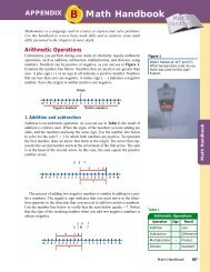
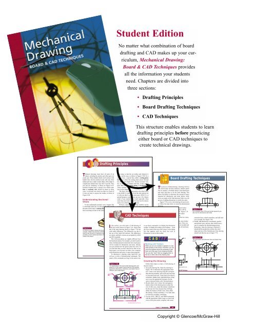
Student Edition<br />
No matter what combination of board<br />
drafting and CAD makes up your curriculum,<br />
Mechanical Drawing:<br />
Board & CAD Techniques provides<br />
all the information your students<br />
need. Chapters are divided into<br />
three sections:<br />
• Drafting Principles<br />
• Board Drafting Techniques<br />
• CAD Techniques<br />
This structure enables students to learn<br />
drafting principles before practicing<br />
either board or CAD techniques to<br />
create technical drawings.<br />
Drafting Principles<br />
T<br />
echnical drawings must show all parts of an taken away, so that the cut surface and whatever is<br />
object, including the insides and other parts not inside can be seen, as shown in Figure 8-1B. On a<br />
easily seen. These hidden details can be drawn with normal view, a special line called a cutting-plane<br />
hidden lines, but this method works well only if the line shows where the cutting plane passes through<br />
hidden part has a rather simple shape. If the shape is the object. See Figure 8-1C. On the sectional view,<br />
complicated, dashed lines may show it poorly. They the cut surface is marked with thin, evenly spaced<br />
can also be confusing, as shown in Figure 8-1A. lines. This is called section lining or crosshatching.<br />
Instead of dashed lines, a special view called a section<br />
or sectional view should be drawn in these later in this chapter.<br />
These concepts will be discussed in greater detail<br />
he process of dimensioning a drawing involves<br />
Tseveral steps. In many instances, drafters prefer<br />
cases. A sectional view shows an object as if part of The basic section lining pattern described above<br />
first to prepare a freehand sketch with dimensions<br />
it were cut away to expose the insides, as shown in is the ANSI 31 symbol. It is not the only pattern, but<br />
and notes and then to do the final drawing. This<br />
Figure 8-1B.<br />
it is the one that is used in most cases. ANSI 31 is a<br />
allows the drafter to determine the amount of space<br />
general-purpose symbol; you can use it for objects<br />
required for dimensions and notes before costly<br />
made of any material. It is used especially when<br />
errors are made on the final drawing. Either way, the<br />
Understanding Sectional<br />
more than one kind of material need not be shown,<br />
process of adding dimensions is exactly the same.<br />
Views<br />
such as on a drawing of a single part.<br />
Figure 7-78 is a two-view drawing of a post socket.<br />
Follow the steps below to create the dimensioned<br />
To best understand sectional views, imagine that However, special section lining symbols can be<br />
a wide-blade knife has cut through the object. Call used to show what materials are to be used. ANSI<br />
drawing.<br />
the path of this knife a cutting plane. Then imagine provides for many symbols to stand for different<br />
1. Prepare a freehand sketch of the post socket<br />
that everything in front of the cutting plane has been materials, as shown in Figure 8-2. Under this system,<br />
views to determine how much space will be<br />
required for dimensions and notes. Figure 7-79<br />
shows the two views with adequate space<br />
CAD Techniques<br />
allowed between and around them.<br />
2. Prepare an instrument drawing of the two views,<br />
complete with centerlines.<br />
3. Study the shape and details of the views before<br />
beginning the dimensioning process. Once you<br />
n this section, you will create a CAD drawing of to use these commands is to are display sure about the Dimension which dimensions are needed and<br />
Ithe post socket shown in Figure 7-81. Notice that toolbar. To display the toolbar, where pick they Toolbars… should be from placed, draw all necessary<br />
Figure 8-1X<br />
this is the same drawing shown in Figure 7-78, but the View menu at the top of the screen. In the dialog<br />
(A) When an object’s internal structure is<br />
complex, hidden lines become confusing or with subtle differences. The differences are due to box that appears, pick<br />
Figure<br />
the check<br />
7-78X<br />
box next to<br />
hard to read. (B and C) A sectional view the use of the AutoCAD A software. The differences Dimension to turn on the toolbar.<br />
Finished drawing of the post socket.<br />
provides a much clearer description of the are minor, and both versions are acceptable by ANSI<br />
inside of the object.<br />
ARROW SHOWS<br />
2X Ø.38<br />
Ø1.12<br />
and ISO standards.<br />
DIRECTION OF<br />
Ø.75<br />
1.00<br />
SECTIONAL<br />
R.60<br />
The CAD procedures are slightly different from<br />
VIEW<br />
the board procedures. For example, you don’t need to<br />
CUTTING PLANE<br />
draw a freehand sketch to determine how much LINE space<br />
will be needed for dimensions and notes. Instead,<br />
Working with Toolbars<br />
When you turn on a toolbar, it appears in a separate<br />
window on the screen. Therefore, you can<br />
you can estimate how far apart to place the views. If<br />
you find later that you have CUT SURFACE allowed IS too SHOWN little BY or SECTION too LINES<br />
1.75<br />
B<br />
move the toolbars around as necessary to get<br />
much space, you can move an entire C view, complete<br />
them out of the way of your drawing activities. 3.50<br />
with dimensions and notes, to space them properly. You can also “dock” them by dragging them 2.10to<br />
To dimension a drawing using AutoCAD, you<br />
Chapter 8 • Sectional Views 277 the top or either side of the drawing area.<br />
will use a series of dimensioning commands. The<br />
names of the commands are long, so the easiest way<br />
1.60<br />
Creating the Drawing<br />
.44<br />
Figure 7-81X<br />
Follow these steps to create a CAD drawing of<br />
(4.70)<br />
The appearance of the post socket drawing when completed<br />
on a CAD system. Notice that the CAD operator<br />
ROUNDS AND FILLETS R.10<br />
the post socket:<br />
1. Set up the drawing file. Study the drawing in<br />
placed the dimensions, centerlines, and hidden lines on<br />
Figure 7-81 to determine<br />
264<br />
the appropriate Mechanical sheet<br />
different, color-coded layers.<br />
Drawing: Board and CAD Techniques<br />
ø1.12<br />
size. Create a new drawing using the corresponding<br />
drawing template, and set the grid and snap<br />
1.00<br />
2X ø.38<br />
2X R.60<br />
ø.75<br />
to convenient intervals. Create layers for objects,<br />
centerlines, hidden lines, and dimensions, being<br />
sure to use the appropriate linetypes. Set the<br />
units to decimal inches with 2 decimal places.<br />
2. Decide which view to draw first and approximately<br />
where in the drawing area to place the<br />
1.75<br />
3.50<br />
view. In this case, create the primary centerlines<br />
Ø2.10<br />
for the top view first, because they will help<br />
define the features of both views. Then offset<br />
the primary vertical centerline 1.75 to both sides<br />
1.60<br />
to create the secondary centerlines.<br />
.44 3. Use the LINE, CIRCLE, and TRIM commands<br />
with the appropriate object snaps to create both<br />
(4.70)<br />
views of the post socket, complete with center<br />
ROUNDS AND FILLETS R.10<br />
Board Drafting Techniques<br />
Figure 7-79X<br />
Two complete views of the post socket spaced to provide<br />
room for dimensions and notes.<br />
extension lines, extend centerlines, and add leaders<br />
as needed. See Figure 7-80.<br />
4. Finally, add dimensions, arrowheads, specific<br />
and general notes, and any other details necessary<br />
to complete the dimensioning process.<br />
Remember, when the drawing is finished, it<br />
should tell the production workers the exact<br />
shape and size of the finished part. Your drawing<br />
should look like the one in Figure 7-78.<br />
Figure 7-80X<br />
The post socket with extension lines and leader lines<br />
added.<br />
Chapter 7 • Dimensioning 265<br />
Copyright © <strong>Glencoe</strong>/McGraw-Hill
V-BLOCK<br />
The Student Edition also includes:<br />
Chapter Review—Contains<br />
a list of summary points and<br />
review questions to help students<br />
check their understanding<br />
of the material presented<br />
in the chapter.<br />
CHAPTER<br />
Chapter Summary<br />
■ Pictorial drawings are useful in engineering,<br />
architecture, advertising, and manufacturing.<br />
■ In isometric drawing, measurements can be<br />
made only on isometric lines.<br />
■ In isometric drawings, circles appear as ellipses.<br />
■ Isometric drawings can be dimensioned using<br />
either aligned or unidirectional dimensioning<br />
methods.<br />
■ Isometric, dimetric, and trimetric are the three<br />
types of axonometric projections.<br />
■ In oblique pictorial drawing, two axes are parallel<br />
to the picture plane.<br />
■ Oblique drawings can be made as cabinet, normal,<br />
and cavalier.<br />
■ A perspective drawing is a three-dimensional<br />
representation of an object as it appears to the<br />
eye from a particular point or location.<br />
■ A technical illustration is a pictorial drawing that<br />
provides technical information using visual<br />
methods.<br />
n Isometric and oblique drawings can be created<br />
using either 2D or 3D techniques in AutoCAD.<br />
Perspective drawings are created in 3D.<br />
Review Questions<br />
1. Describe two uses for pictorial drawings.<br />
2. What are the three most common types of pictorial<br />
drawing?<br />
3. Which type of pictorial drawing is most natural<br />
in appearance?<br />
4. What do you call a line that is not parallel to<br />
any of the three isometric axes?<br />
T<br />
5. Is an isometric projection larger or smaller than<br />
an isometric drawing?<br />
6. Explain why measurements can be taken only<br />
along isometric lines in an isometric drawing.<br />
7. Describe a situation in which a reversed isometric<br />
drawing might be useful.<br />
8. What is the major practical difference between<br />
isometric and dimetric drawings?<br />
9. In what way is an isometric drawing different<br />
from an oblique drawing?<br />
10. In an oblique drawing, how many axes are parallel<br />
to the picture plane?<br />
11. When creating an oblique drawing, how should<br />
you place the object?<br />
12. What is the difference between a cabinet and a<br />
cavalier drawing?<br />
13. Describe the general procedure for developing<br />
a circle on an oblique drawing using board<br />
drafting techniques.<br />
14. What is another name for surface shading?<br />
15. Briefly explain how to create an oblique drawing<br />
using AutoCAD.<br />
16. What is the vanishing point in a perspective<br />
drawing?<br />
17. What two factors affect how an object looks in<br />
perspective?<br />
18. In what way can the grid and snap features of a<br />
CAD program help a drafter create an isometric<br />
drawing?<br />
19. How do you create isometric circles using<br />
AutoCAD?<br />
20. What is the purpose of the DVIEW command in<br />
AutoCAD?<br />
C H A P T E R<br />
Drafting Problems<br />
he drafting problems in this chapter are designed<br />
to be completed using board drafting techniques<br />
or CAD.<br />
Figure 12-75 X<br />
2.50<br />
2.50<br />
24 50<br />
13<br />
76 27<br />
6.00<br />
5.50<br />
130<br />
2.50<br />
1.25<br />
1.25<br />
30<br />
.62<br />
A BRICK<br />
B LAP JOINT<br />
C HOLLOW BLOCK<br />
0'-10<br />
1.25 2.25<br />
2.25<br />
.50<br />
1.00<br />
6.00<br />
5.25<br />
4'-0<br />
1'-8<br />
3.25<br />
2.00<br />
.75 1.38<br />
1.00<br />
CONCRETE STEPS<br />
DOOR STOP .25<br />
D BASE PAD<br />
E F<br />
30<br />
60° .75<br />
30°<br />
2.00<br />
2.50<br />
50<br />
4.00<br />
.25<br />
.75<br />
10<br />
150<br />
5.50<br />
.25<br />
2.00<br />
24 70<br />
30<br />
16<br />
2.00<br />
TOY BOAT<br />
METRIC<br />
1'-4<br />
0'-8<br />
For problems 1 through 15, determine an appropriate<br />
scale and create isometric drawings according<br />
to the instructions for each problem. Do not<br />
dimension.<br />
1. Determine an appropriate scale, and create an isometric<br />
drawing of the object(s) assigned from Figure<br />
12-75. Note: These objects may also be used for<br />
oblique and perspective drawing practice.<br />
METRIC<br />
G H I<br />
SAW BRACKET<br />
.75<br />
1.75<br />
90°<br />
454<br />
Mechanical Drawing: Board and CAD Techniques<br />
Chapter 12 • Pictorial Drawing 455<br />
Drafting Problems—Provide<br />
abundant opportunities for students<br />
to apply their drafting skills.<br />
Design Problems—Challenge<br />
students to apply their drafting<br />
and design skills.<br />
Tech Math—Explanations of how to use the technical<br />
math required in various drafting-related careers.<br />
CAD Tip—Procedural tips and<br />
techniques related to the CAD<br />
procedures in each chapter.<br />
Success on the Job—Workplace tips<br />
to help students work successfully in<br />
drafting-related careers.<br />
Copyright © <strong>Glencoe</strong>/McGraw-Hill
SECTIONAL VIEWS<br />
DRAWN BY<br />
Student Workbook<br />
Drafting and Design Problems<br />
This Student Workbook is packed with<br />
drafting and design problems related to<br />
every chapter in the Student Edition. The<br />
problems, which vary in difficulty from<br />
basic to advanced, are designed to meet the<br />
needs of a broad range of students. You will<br />
find familiar, time-tested standards as well<br />
as new problems related to new material in<br />
the Student Edition.<br />
Problem 8-1: Convert the right-side<br />
view to a full section. Use generalpurpose<br />
section lining.<br />
Problem 8-2: Complete the right-side<br />
view as a full section. Use general-purpose<br />
section lining.<br />
Problem 8-3: Complete the right-side<br />
view as a full section. Use generalpurpose<br />
section lining.<br />
Problem 8-4: Draw the front view as a full<br />
section. Use general-purpose section lining.<br />
Problem 8-5: Draw the front view as<br />
a full section. Use general-purpose<br />
section lining.<br />
Problem 8-6: Draw the front view as<br />
a full section. Use general-purpose<br />
section lining.<br />
Copyright © <strong>Glencoe</strong>/McGraw-Hill<br />
DATE DWG NO.<br />
83<br />
Real-World Problems<br />
“Real-world problems” at the end of the<br />
Student Workbook challenge students to<br />
draw upon their drafting knowledge and<br />
skills to complete problems that drafters<br />
in various disciplines may face routinely.<br />
Copyright © <strong>Glencoe</strong>/McGraw-Hill
www.tifaq.com<br />
Student Workbook<br />
Instructor Annotated Edition<br />
Answers in Place<br />
Answers to problems in the Student Workbook are<br />
shown in color in the new Student Workbook<br />
Instructor Annotated Edition. These answers “in<br />
place” make it easy for you to check student<br />
assignments.<br />
Problem 8-1: Convert the right-side<br />
view to a full section. Use generalpurpose<br />
section lining.<br />
Problem 8-2: Complete the right-side<br />
view as a full section. Use general-purpose<br />
section lining.<br />
Problem 8-3: Complete the right-side<br />
view as a full section. Use generalpurpose<br />
section lining.<br />
Problem 8-4: Draw the front view as a full<br />
section. Use general-purpose section lining.<br />
Name ___________________________ Class __________________ Date ___________________________<br />
Problem 8-5: Draw the front view as<br />
a full section. Use general-purpose<br />
section lining.<br />
Problem 8-6: Draw the front view as<br />
a full section. Use general-purpose<br />
section lining.<br />
Activity 3<br />
Copy Holder Design<br />
You work for the research and development unit of a company that manufactures office accessories. Your<br />
team has been asked to develop a copy holder for data entry specialists. (A data entry specialist is a person<br />
who enters data from hard copy into a computer database or spreadsheet.) Based on market research, management<br />
has requested the following features:<br />
• adjustable viewing angle<br />
over easily)<br />
• means of illuminating the papers on the copy holder<br />
DATE DWG NO.<br />
• method of keeping papers in place on the copy stand (so that they don’t blow off or curl and fall<br />
• space for a minimum of 100 sheets of paper<br />
Part I: Research<br />
83<br />
SECTIONAL VIEWS<br />
Copyright © <strong>Glencoe</strong>/McGraw-Hill<br />
DRAWN BY<br />
Ergonomics and ease of use are important considerations for any kind of office equipment. For example,<br />
you will need to determine the angles at which the papers are held on the stand, the brightness and direction<br />
of the light, and even the source of the light.<br />
1. Search for information about the best angle for viewing copy while seated at a computer workstation.<br />
Different sources may suggest slightly different angles, but that is good. Recall that your design<br />
specifications include an adjustable viewing angle. List your sources and the angles they suggest on<br />
the lines below. Then indicate the range of angles you will provide in your copy holder design.<br />
__________________________________________________________________________________<br />
Helpful Web sites include those of most major computer manufacturers. Examples include:<br />
__________________________________________________________________________________<br />
www.compaq.com/comfortguide<br />
__________________________________________________________________________________<br />
Range of angles for copy holder: _______________________________________________________<br />
2. What type of lighting is best for this application? Should you specify incandescent or fluorescent<br />
light? How will the light be powered? Will you need a power cord, or will the light be batterypowered?<br />
If a power cord is needed, how long should it be? If a battery is needed, how big will it need<br />
to be, and how will the battery fit into the overall design? Record your notes on the lines below.<br />
Helpful Web sites include:<br />
__________________________________________________________________________________<br />
www.safetyoffice.uwaterloo.ca<br />
__________________________________________________________________________________<br />
__________________________________________________________________________________<br />
www.cdc.gov/niosh/homepage.html<br />
__________________________________________________________________________________<br />
__________________________________________________________________________________<br />
__________________________________________________________________________________<br />
__________________________________________________________________________________<br />
254 Copyright © <strong>Glencoe</strong>/McGraw-Hill<br />
Copyright © <strong>Glencoe</strong>/McGraw-Hill
Instructor Resource Guide<br />
This Instructor Resource Guide is a powerful<br />
resource that provides numerous teaching aids<br />
and activities to help you deliver well-rounded<br />
instruction.<br />
Instructional Plans include:<br />
• Chapter objectives to help you focus and plan lessons<br />
• List of pertinent drafting standards (ANSI and ISO)<br />
• Several student activity ideas<br />
• List of related components in the Mechanical<br />
Drawing program<br />
• Written and performance assessment assignments<br />
• Answers to chapter review questions<br />
Copyright © <strong>Glencoe</strong>/McGraw-Hill
Chapter Handouts reinforce and extend<br />
instruction from the Student Edition. One<br />
of the handouts for each chapter is<br />
a glossary of terms from which students<br />
can build a complete drafting dictionary.<br />
Testing Program helps you<br />
assess student mastery of the<br />
principles and skills developed<br />
in each chapter.<br />
WORKPLACE AND<br />
COMPUTER SKILLS<br />
DRAFTING<br />
RESOURCES<br />
CHAPTER<br />
TESTS<br />
ANSWERS TO TEXTBOOK PROBLEMS<br />
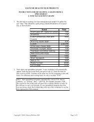
Other resources include tips for managing a technical<br />
drawing program, information about computer/Internet use<br />
and workplace skills, and answers to drafting problems in<br />
the textbook.<br />
Copyright © <strong>Glencoe</strong>/McGraw-Hill
Copyright © <strong>Glencoe</strong>/McGraw-Hill