SW-V2.1 1255 service manual.pdf - Genius
SW-V2.1 1255 service manual.pdf - Genius
SW-V2.1 1255 service manual.pdf - Genius

Create successful ePaper yourself
Turn your PDF publications into a flip-book with our unique Google optimized e-Paper software.
Service Guide <strong>SW</strong>-<strong>V2.1</strong> <strong>1255</strong><br />
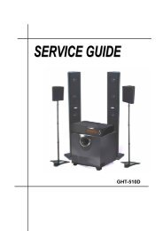
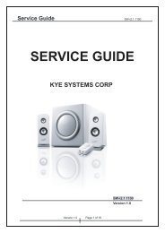
SERVICE GUIDE<br />
KYE SYSTEMS CORP<br />
<strong>SW</strong>-<strong>V2.1</strong> <strong>1255</strong><br />
Version:1.0<br />
Version 1.0 Page 1 of 15
Service Guide<br />
<strong>SW</strong>-<strong>V2.1</strong> <strong>1255</strong><br />
Revision History<br />
Version Date Change<br />
1.0 24/08/2007<br />
Version 1.0 Page 2 of 15
Service Guide<br />
<strong>SW</strong>-<strong>V2.1</strong> <strong>1255</strong><br />
Table of Contents<br />
Revision History 2<br />
Table of Contents 3<br />
Getting Started 4<br />
Conventions Used in this Guide 4<br />
Safety Precautions 4<br />
Chapter 1. How to Handle Defective Returns 5<br />
1.1 Overview 5<br />
1.2 Problems 6<br />
1.2.1 L/R channels no sound 7<br />
1.2.2 Woofer channel no sound 8<br />
1.2.3 No power 8<br />
Chapter 2. Specifications Satellite 9<br />
Host(Woofer) 9<br />
Chapter 3. Block Diagram 10<br />
Chapter 4. Exploded View Host(Woofer)/Satellite 11<br />
Controller 12<br />
Chapter 5. Part List 13<br />
Chapter 6. Schematic Diagram 14<br />
Chapter 7. Important Notes 15<br />
7.1 Packing Requirement for Sending the PCB Assembly by post 15<br />
7.2 Short of Spare Parts while Repairing a Speaker system 15<br />
Version 1.0 Page 3 of 15
Service Guide<br />
<strong>SW</strong>-<strong>V2.1</strong> <strong>1255</strong><br />
Chapter 1. How to Handle Defective Returns<br />
1.1 Overview<br />
Receiving Defective speaker form customers<br />
Verifying problems<br />
proceeding<br />
necessary tests<br />
Function NG<br />
Function NG<br />
Analyzing possible<br />
malfunction causes<br />
Function OK<br />
Deciding & proceeding the<br />
rectification methods<br />
Replace necessary<br />
defective parts<br />
Proceeding tests to<br />
verify if the speaker is<br />
functioning normally<br />
Function OK<br />
Return the speakers with proper<br />
repackaging to customers<br />
Version 1.0 Page 5 of 15
Service Guide<br />
<strong>SW</strong>-<strong>V2.1</strong> <strong>1255</strong><br />
1.2 Problems<br />
Item<br />
Problem Description<br />
1.2.1 L/R channels no sound<br />
1.2.2 Woofer channel no sound<br />
1.2.3 NO power<br />
Version 1.0 Page 6 of 15
Service Guide<br />
<strong>SW</strong>-<strong>V2.1</strong> <strong>1255</strong><br />
* Attention<br />
Please follow the numbered sequence marked within parenthesis given in individual<br />
Flow chat, in that this is the best-recommended sequence to rectify the problems.<br />
1.2.1 L/R channels no sound<br />
Problem<br />
L/R channels no sound<br />
Analyze and<br />
Identify the Causes<br />
Broken or short circuit<br />
Defective<br />
VOL,BASS,IC1,IC6,F2,<br />
U6<br />
Speaker cable dis-connect or<br />
speaker damaged<br />
Solutions<br />
Check solder points on<br />
PCB<br />
Check and replace<br />
defective IC or<br />
components<br />
Re-connected speaker cable<br />
or replace defective speakers<br />
Version 1.0 Page 7 of 15
Service Guide<br />
<strong>SW</strong>-<strong>V2.1</strong> <strong>1255</strong><br />
1.2.2 Woofer channel no sound<br />
Problem<br />
Woofer channel no sound<br />
Analyze and<br />
Identify the Causes<br />
Broken or short circuit<br />
Defective<br />
BASS,IC1,F2,U7<br />
Speaker cable dis-connect or<br />
speaker damaged<br />
Solutions<br />
Check solder points on<br />
PCB<br />
Check and replace<br />
defective IC or<br />
components<br />
Re-connected speaker cable<br />
or replace defective speakers<br />
1.2.3 No power<br />
Problem<br />
No power<br />
Analyze and<br />
Identify the Causes<br />
Broken or short<br />
circuit<br />
Defective<br />
F2,D7,D8,D11,<br />
D12,IC2<br />
Speaker cable<br />
dis-connect or<br />
speaker damaged<br />
Transfor mer<br />
damaged<br />
Solutions<br />
Check solder points<br />
on PCB<br />
Check and replace<br />
defective components<br />
Re-connected<br />
speaker cable<br />
or replace def<br />
ective speakers<br />
Replace defective<br />
trans for mer<br />
Version 1.0 Page 8 of 15
Service Guide<br />
<strong>SW</strong>-<strong>V2.1</strong> <strong>1255</strong><br />
Chapter 2. Specifications<br />
Satellite – Front (AT 1KHZ):<br />
NO Description Unit Specifications<br />
1 Out Power at THD 10% W 10± 2<br />
2 Sensitivity mV 740 ± 80<br />
3 Freq Response (Ref:-3dB) Hz 220 ~20K<br />
4 Separation dB > 30<br />
5 S/N ratio dB > 60<br />
6 Hum & Noise Vol:max mV 50<br />
5 Hum & Noise Vol: max mV
Service Guide<br />
<strong>SW</strong>-<strong>V2.1</strong> <strong>1255</strong><br />
Chapter 3. Block Diagram<br />
LINE CONTRO L<br />
L R<br />
L SPEAKER<br />
LIN SCH<br />
VOL SCH<br />
B10K<br />
AV4558<br />
AMP SCH<br />
TDA8947<br />
R SPEAKER<br />
SUB<br />
AV4558<br />
SUB SPEAKER<br />
AC IN<br />
power sch<br />
AC IN<br />
POWER SUPPLY<br />
Version 1.0 Page 10 of 15
Service Guide<br />
<strong>SW</strong>-<strong>V2.1</strong> <strong>1255</strong><br />
Chapter 4. Exploded View<br />
Host (Woofer)<br />
Switch<br />
Rear panel<br />
PCBA<br />
Speaker driver(woofer)<br />
Trans former<br />
Port tube1<br />
Port tube2<br />
Wooden case<br />
Rubber foot<br />
Garnishry<br />
Panel<br />
Satellite<br />
Cover<br />
Driver<br />
Cuse<br />
Mesh frame<br />
Garni shry<br />
Bracket<br />
Nameplate<br />
Eva felt<br />
Version 1.0 Page 11 of 15
Service Guide<br />
<strong>SW</strong>-<strong>V2.1</strong> <strong>1255</strong><br />
Volume control<br />
Main volume knob<br />
Bass adjust knob<br />
Standby/on button<br />
LED guide<br />
Cover<br />
Cable<br />
PCBA<br />
Bottom cover<br />
EVA felt<br />
Version 1.0 Page 12 of 15
Service Guide<br />
<strong>SW</strong>-<strong>V2.1</strong> <strong>1255</strong><br />
Chapter 5. Part List<br />
NO DESCRIPTION Qty UNIT Part No<br />
1 <strong>SW</strong>-<strong>V2.1</strong> <strong>1255</strong>/BODY/SATELLITE-FL 1 PC 220133260209<br />
2 <strong>SW</strong>-<strong>V2.1</strong> <strong>1255</strong>/BODY/SATELLITE-FR 1 PC 220133260219<br />
3 <strong>SW</strong>-<strong>V2.1</strong> <strong>1255</strong>/BODY/WOOFER/230V-EU 1 PC 220133220109<br />
4 SPEAKER UNIT 5.25" 8 OHM 30WT 1 PC 20280650300702<br />
5 SPEAKER UNIT 1.5" 4 12HM 3W 1 PC 20110150030901<br />
6 RUBBER, WOOFER 4 PC 420500190209<br />
7 EVA FELT SATELLITE 8 PC 420001330129<br />
8 MANUAL,<strong>SW</strong>-<strong>V2.1</strong> 1250 1 PC 462513326009<br />
9 PCBA <strong>SW</strong>-<strong>V2.1</strong> 1250 1 PC 301133260029<br />
10 IC 4558 ST 3 SET 403100020149<br />
11 TDA8947<br />
1 PC 403000200109<br />
12 ROTARY <strong>SW</strong>ITCH, 10k L=200mm<br />
2 PC 401410021109<br />
13 ROTARY <strong>SW</strong>ITCH, 10k L=15mm<br />
1 PC 401410021209<br />
14 CARTON,<strong>SW</strong>-<strong>V2.1</strong> <strong>1255</strong><br />
1 PC 462113326009<br />
15 TRANSFORMER,230V 17x2.5A<br />
1 PC 412001400109<br />
16 AUDIO CABLE D3.5 L1.5M<br />
2 PC 461461520089<br />
17 AUDIO CABLE 2RCA to 3.5mm Coinveltir 10cm 1 PC 461451000019<br />
18 CARTON LABEL<br />
1 PC 462705090049<br />
19 S/N LABEL<br />
2 PC 462700370049<br />
20 Round Red type Label, D18MM<br />
1 PC 462700300079<br />
21 PO BAG,<strong>SW</strong>-<strong>V2.1</strong> <strong>1255</strong>(Satellite)<br />
2 PC 462640351319<br />
22 PO BAG,<strong>SW</strong>-<strong>V2.1</strong> <strong>1255</strong>(Woofer)<br />
1 PC 462610626009<br />
23 PO BAG,<strong>SW</strong>-<strong>V2.1</strong> <strong>1255</strong>(VOLUME CONTROL) 1 PC 462640161019<br />
24 PE BAG,<strong>SW</strong>-<strong>V2.1</strong> <strong>1255</strong>(Audio cable) 2 PC 462620231259<br />
Version 1.0 Page 13 of 15
Service Guide<br />
<strong>SW</strong>-<strong>V2.1</strong> <strong>1255</strong><br />
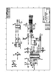
Chapter 6. Schematic Diagram<br />
Version 1.0 Page 14 of 15
Service Guide<br />
<strong>SW</strong>-<strong>V2.1</strong> <strong>1255</strong><br />
Chapter 7. Important Notes<br />
7.1 Packing Requirement for Sending the PCB Assembly by Post<br />
PCB assembly is a kind of sophisticated electronic circuit board. Well<br />
packing will be required when sending them by post.<br />
* Some sophisticated IC components are mounted on the PCB assembly,<br />
hence it is necessary to pack each PCB assembly with a separate static<br />
protecting bag, in order to avoid static electricity.<br />
* Reliable external packing is also very important when sending PCB<br />
assembly by post, in that it would avoid unnecessarily lost or damage.<br />
7.2 Short of Spare Parts while Repairing a Speaker System<br />
If you are short of spare parts when you have some speaker systems waiting<br />
to be repaired, it would be recommended to take the necessary parts form<br />
one speaker system, so that you may have the as many speaker systems.<br />
Version 1.0 Page 15 of 15