Variant selection of primary, secondary and tertiary twins in a ...
Variant selection of primary, secondary and tertiary twins in a ...
Variant selection of primary, secondary and tertiary twins in a ...

Create successful ePaper yourself
Turn your PDF publications into a flip-book with our unique Google optimized e-Paper software.
2046 S. Mu et al. / Acta Materialia 60 (2012) 2043–2053<br />
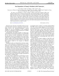
Fig. 2. (a) EBSD map measured at a stra<strong>in</strong> <strong>of</strong> e = 0.11 (the gra<strong>in</strong> outl<strong>in</strong>ed <strong>in</strong> red is <strong>of</strong> <strong>in</strong>terest)—the regions separated by high-angle boundaries are<br />
identified by colors related to their orientations (Euler angles); (b) the most frequently observed tw<strong>in</strong> types <strong>in</strong> Mg alloys are listed together with the<br />
correspond<strong>in</strong>g disorientations with respect to the matrix given <strong>in</strong> m<strong>in</strong>imum angle-axis pairs; (c) disorientation distribution; (d) (0002) PF for the<br />
e = 0.11 sample; (e) the Euler angle color code.<br />
these are boundaries between: (i) ETWs <strong>and</strong> the matrix<br />
(ETW–MAT with a characteristic disorientation <strong>of</strong> 86°<br />
h 12 10i), <strong>and</strong> (ii) two ETWs <strong>of</strong> different types (ETW–<br />
ETW with a characteristic disorientation <strong>of</strong> 60 h10 10i),<br />
respectively. The high frequency <strong>of</strong> ETW–MAT <strong>and</strong><br />
ETW–ETW boundaries <strong>in</strong>dicates that there was massive<br />
activation <strong>and</strong> growth <strong>of</strong> <strong>primary</strong> ETWs up to the stra<strong>in</strong> level<br />
employed.<br />
The formation <strong>of</strong> such ETW–ETW boundaries can be<br />
understood as follows. Although a gra<strong>in</strong> can theoretically<br />
tw<strong>in</strong> on any <strong>of</strong> the six f1 0 12g planes, those <strong>tw<strong>in</strong>s</strong> can<br />
be assumed to nucleate where the resolved shear stress on<br />
the tw<strong>in</strong>n<strong>in</strong>g plane <strong>and</strong> <strong>in</strong> the shear direction exceeds the<br />
critical value s c . When two or three ETW variants form<br />
<strong>in</strong> a particular matrix gra<strong>in</strong>, one tw<strong>in</strong> will generally nucleate<br />
first, after which the second (<strong>and</strong> third) ETWs nucleate<br />
at slightly larger stra<strong>in</strong>s <strong>and</strong> applied stresses. Accord<strong>in</strong>g to<br />
this view, the ETWs grow <strong>in</strong>to the matrix cont<strong>in</strong>uously<br />
until stra<strong>in</strong><strong>in</strong>g ceases or their boundaries collide with the<br />
other <strong>tw<strong>in</strong>s</strong> or the gra<strong>in</strong> boundary.<br />
Another slight peak <strong>in</strong> the disorientation distribution<br />
appears at 30–45° about the h 12 10i rotation axis. These<br />
disorientations can be classified as boundaries between the<br />
matrix <strong>and</strong> f1 0 11g–f1 0 12g double <strong>tw<strong>in</strong>s</strong>. This set <strong>of</strong><br />
frequently detected boundaries <strong>in</strong>dicates that a second generation<br />
<strong>of</strong> CTWs formed with<strong>in</strong> the first-generation ETWs.<br />
As most gra<strong>in</strong>s <strong>in</strong>itially had their c-axes aligned with LD,<br />
the conditions were not favorable for the formation <strong>of</strong><br />
first-generation CTWs. Once ETWs formed <strong>and</strong> reoriented<br />
the tw<strong>in</strong>ned part <strong>of</strong> a gra<strong>in</strong> by rotat<strong>in</strong>g the c-axis about the<br />
h 12 10i by 86°, align<strong>in</strong>g it with CD, contraction tw<strong>in</strong>n<strong>in</strong>g<br />
could take place dur<strong>in</strong>g further compression. In this way,<br />
the first generation ETWs became the “matrix” for the secondgeneration<br />
CTWs. Meanwhile, a still smaller peak with<br />
much lower frequency appears <strong>in</strong> the range 50–65° about<br />
the h 12 10i axis, which corresponds to f1 0 11g CTWs.<br />
To differentiate among the three generations <strong>of</strong> <strong>tw<strong>in</strong>s</strong>, they<br />
are labeled here as <strong>primary</strong> ETWs, <strong>secondary</strong> CTWs, <strong>and</strong><br />
<strong>tertiary</strong> ETWs.<br />
The macrotexture measured on the surface perpendicular<br />
to CD at e = 0.11 is presented <strong>in</strong> the form <strong>of</strong> a (0002) PF<br />
<strong>in</strong> Fig. 2d. On comparison with the <strong>in</strong>itial texture shown <strong>in</strong><br />
Fig. 1b, it can be seen that the orig<strong>in</strong>al LD texture component<br />
(c-axes parallel to LD) has disappeared <strong>and</strong> been<br />
replaced with three texture components: the newly generated<br />
CD basal component (c-axes parallel to CD with an