Fatigue in thin films Lifetime and damage formation.pdf
Fatigue in thin films Lifetime and damage formation.pdf
Fatigue in thin films Lifetime and damage formation.pdf

Create successful ePaper yourself
Turn your PDF publications into a flip-book with our unique Google optimized e-Paper software.
922<br />
O. Kraft et al. / Materials Science <strong>and</strong> Eng<strong>in</strong>eer<strong>in</strong>g A319–321 (2001) 919–923<br />
3.2. Microbeam bend<strong>in</strong>g<br />
The gra<strong>in</strong>s <strong>in</strong> the Ag <strong>films</strong> on the SiO 2 microbeams<br />
were found to be columnar <strong>and</strong> had a median gra<strong>in</strong> size<br />
of about 0.9 m <strong>in</strong>dependent of the film thickness. The<br />
majority of gra<strong>in</strong>s was (111)-oriented with a smaller<br />
fraction of (100)-oriented gra<strong>in</strong>s. The latter <strong>in</strong>creased<br />
with <strong>in</strong>creas<strong>in</strong>g film thickness. As an example of a<br />
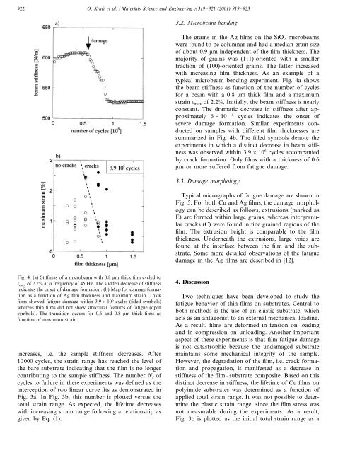
typical microbeam bend<strong>in</strong>g experiment, Fig. 4a shows<br />
the beam stiffness as function of the number of cycles<br />
for a beam with a 0.8 m thick film <strong>and</strong> a maximum<br />
stra<strong>in</strong> max of 2.2%. Initially, the beam stiffness is nearly<br />
constant. The dramatic decrease <strong>in</strong> stiffness after approximately<br />
6×10 −5 cycles <strong>in</strong>dicates the onset of<br />
severe <strong>damage</strong> <strong>formation</strong>. Similar experiments conducted<br />
on samples with different film thicknesses are<br />
summarized <strong>in</strong> Fig. 4b. The filled symbols denote the<br />
experiments <strong>in</strong> which a dist<strong>in</strong>ct decrease <strong>in</strong> beam stiffness<br />
was observed with<strong>in</strong> 3.9×10 6 cycles accompanied<br />
by crack <strong>formation</strong>. Only <strong>films</strong> with a thickness of 0.6<br />
m or more suffered from fatigue <strong>damage</strong>.<br />
3.3. Damage morphology<br />
Typical micrographs of fatigue <strong>damage</strong> are shown <strong>in</strong><br />
Fig. 5. For both Cu <strong>and</strong> Ag <strong>films</strong>, the <strong>damage</strong> morphology<br />
can be described as follows, extrusions (marked as<br />
E) are formed with<strong>in</strong> large gra<strong>in</strong>s, whereas <strong>in</strong>tergranular<br />
cracks (C) were found <strong>in</strong> f<strong>in</strong>e gra<strong>in</strong>ed regions of the<br />
film. The extrusion height is comparable to the film<br />
thickness. Underneath the extrusions, large voids are<br />
found at the <strong>in</strong>terface between the film <strong>and</strong> the substrate.<br />
Some more detailed observations of the fatigue<br />
<strong>damage</strong> <strong>in</strong> the Ag <strong>films</strong> are described <strong>in</strong> [12].<br />
Fig. 4. (a) Stiffness of a microbeam with 0.8 m thick film cycled to<br />
max of 2.2% at a frequency of 45 Hz. The sudden decrease of stiffness<br />
<strong>in</strong>dicates the onset of <strong>damage</strong> <strong>formation</strong>. (b) Map for <strong>damage</strong> <strong>formation</strong><br />
as a function of Ag film thickness <strong>and</strong> maximum stra<strong>in</strong>. Thick<br />
<strong>films</strong> showed fatigue <strong>damage</strong> with<strong>in</strong> 3.9×10 6 cycles (filled symbols)<br />
whereas th<strong>in</strong> <strong>films</strong> did not show structural features of fatigue (open<br />
symbols). The transition occurs for 0.6 <strong>and</strong> 0.8 m thick <strong>films</strong> as<br />
function of maximum stra<strong>in</strong>.<br />
<strong>in</strong>creases, i.e. the sample stiffness decreases. After<br />
10000 cycles, the stra<strong>in</strong> range has reached the level of<br />
the bare substrate <strong>in</strong>dicat<strong>in</strong>g that the film is no longer<br />
contribut<strong>in</strong>g to the sample stiffness. The number N f of<br />
cycles to failure <strong>in</strong> these experiments was def<strong>in</strong>ed as the<br />
<strong>in</strong>terception of two l<strong>in</strong>ear curve fits as demonstrated <strong>in</strong><br />
Fig. 3a. In Fig. 3b, this number is plotted versus the<br />
total stra<strong>in</strong> range. As expected, the lifetime decreases<br />
with <strong>in</strong>creas<strong>in</strong>g stra<strong>in</strong> range follow<strong>in</strong>g a relationship as<br />
given by Eq. (1).<br />
4. Discussion<br />
Two techniques have been developed to study the<br />
fatigue behavior of th<strong>in</strong> <strong>films</strong> on substrates. Central to<br />
both methods is the use of an elastic substrate, which<br />
acts as an antagonist to an external mechanical load<strong>in</strong>g.<br />
As a result, <strong>films</strong> are deformed <strong>in</strong> tension on load<strong>in</strong>g<br />
<strong>and</strong> <strong>in</strong> compression on unload<strong>in</strong>g. Another important<br />
aspect of these experiments is that film fatigue <strong>damage</strong><br />
is not catastrophic because the un<strong>damage</strong>d substrate<br />
ma<strong>in</strong>ta<strong>in</strong>s some mechanical <strong>in</strong>tegrity of the sample.<br />
However, the degradation of the film, i.e. crack <strong>formation</strong><br />
<strong>and</strong> propagation, is manifested as a decrease <strong>in</strong><br />
stiffness of the film–substrate composite. Based on this<br />
dist<strong>in</strong>ct decrease <strong>in</strong> stiffness, the lifetime of Cu <strong>films</strong> on<br />
polyimide substrates was determ<strong>in</strong>ed as a function of<br />
applied total stra<strong>in</strong> range. It was not possible to determ<strong>in</strong>e<br />
the plastic stra<strong>in</strong> range, s<strong>in</strong>ce the film stress was<br />
not measurable dur<strong>in</strong>g the experiments. As a result,<br />
Fig. 3b is plotted as the <strong>in</strong>itial total stra<strong>in</strong> range as a