RF Electronic Programmable Thermostat, 7 Day - Ideal Heating
RF Electronic Programmable Thermostat, 7 Day - Ideal Heating
RF Electronic Programmable Thermostat, 7 Day - Ideal Heating

You also want an ePaper? Increase the reach of your titles
YUMPU automatically turns print PDFs into web optimized ePapers that Google loves.
<strong>RF</strong> <strong>Electronic</strong> <strong>Programmable</strong> Room<br />
<strong>Thermostat</strong>, 7 day FITTING INSTRUCTIONS<br />
This Timer is suitable for installation on the following products:<br />
Logic Combi 24............................................. G.C. No. 47-348-56<br />
Logic Combi 30............................................. G.C. No. 47-348-57<br />
Logic Combi 35............................................. G.C. No. 47-348-58<br />
Logic + Combi 24.......................................... G.C. No. 47-348-65<br />
Logic + Combi 30.......................................... G.C. No. 47-348-66<br />
Logic + Combi 35.......................................... G.C. No. 47-348-67<br />
Logic Code Combi 26.................................... G.C. No. 47-348-74<br />
Logic Code Combi 33.................................... G.C. No. 47-348-75<br />
Logic Code Combi 38.................................... G.C. No. 47-348-76<br />
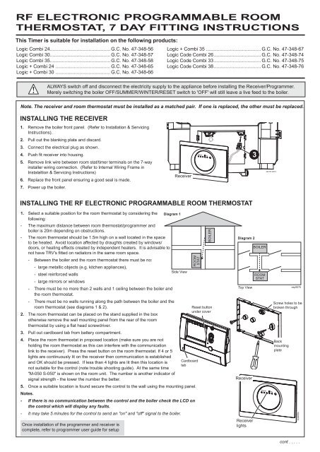
ALWAYS switch off and disconnect the electricity supply to the appliance before installing the Receiver/Programmer.<br />
Merely switching the boiler OFF/SUMMER/WINTER/RESET switch to 'OFF' will still leave a live feed to the boiler.<br />
Note. The receiver and room thermostat must be installed as a matched pair. If one is replaced, the other must be replaced.<br />
INSTALLING THE Receiver<br />
1. Remove the boiler front panel. (Refer to Installation & Servicing<br />
Instructions).<br />
2. Pull out the blanking plate and discard.<br />
3. Connect the electrical plug as shown.<br />
4. Push fit receiver into housing.<br />
5. Remove link wire between room stat/timer terminals on the 7-way<br />
installer wiring connection. (Refer to Internal Wiring Frame in<br />
Instalaltion & Servicing Instructions)<br />
6. Replace the front panel ensuring a good seal is made.<br />
7. Power up the boiler.<br />
Receiver<br />
INSTALLING THE <strong>RF</strong> <strong>Electronic</strong> <strong>Programmable</strong> Room <strong>Thermostat</strong><br />
Signal<br />
Diagram 1<br />
3<br />
204797-9601c<br />
BOILER<br />
1. Select a suitable position for the room thermostat by considering the Diagram 1<br />
following:<br />
- The maximum distance between room thermostat/programmer and<br />
boiler is 20m depending on obstructions.<br />
- The room thermostat should be 1.5m high on a wall located in the space<br />
to be heated. Avoid location affected by draughts created by windows/<br />
doors, or heating effects created by independent heaters. It is advisable to<br />
not have TRV's fitted on radiators in the same room space.<br />
- Between the boiler and the room thermostat there must be no:<br />
- large metallic objects (e.g. kitchen appliances),<br />
Side View<br />
- steel reinforced walls<br />
- large mirrors or windows<br />
Diagram 2<br />
- There must be no more than 2 walls and 1 ceiling between the boiler and<br />
BOILER<br />
the room thermostat.<br />
- There must be no walls running along the path between the boiler and the<br />
room thermostat (see diagrams 1 & 2).<br />
2. The room thermostat can be placed on the stand supplied in the box<br />
otherwise remove the wall mounting panel from the rear of the room<br />
ROOM<br />
STAT<br />
thermostat by using a flat head screwdriver.<br />
3. Pull out cardboard tab from battery compartment.<br />
Top View<br />
4. Place the room thermostat in proposed location (make sure you are not<br />
holding the room thermostat as this can interfere with the communication<br />
link to the receiver). Press the reset button on the room thermostat. If 4 or 5<br />
lights are continuously lit on the receiver then communication is established<br />
and OK should be pressed. If less than 4 lights are lit then this location is<br />
Cardboard<br />
tab<br />
not suitable for the control (note trouble shooting guide). At the same time<br />
"M-050 S-050" is shown on the room unit. The number is another indicator of<br />
signal strength - the lower the number the better.<br />
5. Once a suitable location is found secure the control to the wall using the mounting panel.<br />
Notes.<br />
- If there is no communication between the control and the boiler check the LCD on<br />
the control which will display any faults.<br />
- It may take 5 minutes for the control to send an "on" and "off" signal to the boiler.<br />
Once installation of the programmer and receiver is<br />
complete, refer to programmer user guide for setup<br />
ROOM<br />
STAT<br />
BOILER<br />
Reset button<br />
under cover<br />
esp9575<br />
Side View<br />
Diagram 2<br />
Top View<br />
Receiver<br />
Receiver<br />
lights<br />
ROOM<br />
STAT<br />
BOILER<br />
ROOM<br />
STAT<br />
Signal<br />
Back<br />
mounting<br />
plate<br />
esp9575<br />
Screw holes to be<br />
broken through<br />
3G9602b<br />
cont . . . . .
Trouble Shooting<br />
FAUlt<br />
Central <strong>Heating</strong> will not switch on<br />
Central <strong>Heating</strong> will not switch off<br />
action<br />
Check that the room thermostat is set to "CONT ON" or is in a programmed period<br />
Check that the room temperature is set to 30 o C (press the "+" key on the room control until temperature<br />
= 30 o C)<br />
Check that the power to the boiler is switched on<br />
Ensure that the "MODE" knob on the front of the boiler is in the winter<br />
Change the batteries in the room thermostat<br />
position<br />
Press the reset button on the room thermostat if less than 4 lights are lit on the receiver then<br />
the room thermostat is either too far away front the boiler or there are unsuitable materials in<br />
between the boiler and the room thermostat (note diagrams 1 & 2)<br />
Replace both the receiver and the room thermostat for a new pair.<br />
Check that the room thermostat is set to "CONT OFF" or is in a programmed off period<br />
Press the reset button on the room thermostat if less than 4 lights are lit on the receiver (fig 8)<br />
then the room thermostat is either too far away from the boiler or there are unsuitable materials<br />
in between the boiler and the room thermostat<br />
Change the batteries in the room thermostat.<br />
Replace both the receiver and the room thermostat for a new pair.<br />
BATTERY REPLACEMENT<br />
Batteries should operate for approximately 18 to 24 months.<br />
Only good quality alkaline batteries should be used.<br />
To replace batteries remove battery panel on the front of the<br />
room thermostat and replace the batteries. Refit the battery<br />
panel.<br />
Note that if the batteries are removed for more than 30 secs,<br />
the time, date and set temperature will be lost.<br />
If the batteries are not replaced and no signal is received by<br />
the receiver all 5 lights on the receiver on the boiler will flash on<br />
and off.<br />
After 1 hour the boiler will operate in "Emergency Mode" with<br />
a continuous, but reduced temperature until the batteries are<br />
replaced.<br />
Batteries - 2x 1.5V LR6/AA<br />
<strong>Ideal</strong> Boilers Ltd. , P.O. Box 103, National Avenue, Kingston upon Hull, HU5 4JN.<br />
Telephone: 01482 492 251 Fax: 01482 448 858. Registration No. London 322 137. November 2010 UIN 204797 A05<br />
<strong>Ideal</strong> Stelrad Group pursues a policy of continuing<br />
improvement in the design and performance of its products.<br />
The right is therefore reserved to vary specification without notice.