USERS GUIDE - Independent C24, C30, C35 - Ideal Heating
USERS GUIDE - Independent C24, C30, C35 - Ideal Heating
USERS GUIDE - Independent C24, C30, C35 - Ideal Heating

You also want an ePaper? Increase the reach of your titles
YUMPU automatically turns print PDFs into web optimized ePapers that Google loves.
<strong>USERS</strong> <strong>GUIDE</strong><br />
<strong>Independent</strong><br />
<strong>C24</strong>, <strong>C30</strong>, <strong>C35</strong><br />
For installation guide see reverse of book<br />
When replacing any part on this appliance, use only spare parts that you can be<br />
assured conform to the safety and performance specification that we require.<br />
Do not use reconditioned or copy parts that have not been clearly authorised by <strong>Ideal</strong>.
Introduction<br />
The <strong>Independent</strong> is a wall mounted, room sealed, condensing<br />
combination boiler, featuring full sequence automatic spark ignition<br />
and fan assisted combustion.<br />
Due to the high efficiency of the boiler, condensate is produced from<br />
the flue gases and this is drained to a suitable disposal point through<br />
a plastic waste pipe at the base of the boiler. A condensate ‘plume’<br />
will also be visible at the flue terminal.<br />
The <strong>Independent</strong> is a combination boiler providing both central<br />
heating and instantaneous domestic hot water.<br />
Safety<br />
Current Gas Safety (Installation & Use)<br />
regulations or rules in force.<br />
In your own interest, and that of safety, it is the law that this boiler<br />
must be installed by a Gas Safe Registered Engineer, in accordance<br />
with the above regulations.<br />
In IE, the installation must be carried out by a Registered Gas Installer<br />
(RGII) and installed in accordance with the current edition of I.S. 813<br />
“Domestic Gas Installations”, the current Building Regulations and<br />
reference should be made to the current ETCI rules for electrical<br />
installation.<br />
It is essential that the instructions in this booklet are strictly followed,<br />
for safe and economical operation of the boiler.<br />
Electricity Supply<br />
This appliance must be earthed.<br />
FOR aNy qUERIEs pLEasE RINg ThE<br />
IDEaL CONsUMER hELpLINE : 01482 498660<br />
NOTE. BOILER REsET pROCEDURE -<br />
To reset boiler, turn mode control knob to reset position and immediately turn knob back to required setting.<br />
supply: 230 V ~ 50 hz. The fusing should be 3a.<br />
important notes<br />
� This appliance must not be operated without the casing correctly<br />
fitted and forming an adequate seal.<br />
� If the boiler is installed in a compartment then the compartment<br />
MUST NOT be used for storage purposes.<br />
� If it is known or suspected that a fault exists on the boiler then<br />
it MUST NOT BE USED until the fault has been corrected by a<br />
Gas Safe Registered Engineer or in IE a Registered Gas Installer<br />
(RGII).<br />
� Under NO circumstances should any of the sealed components on<br />
this appliance be used incorrectly or tampered with.<br />
� This appliance is not intended for use by persons (including<br />
children) with reduced physical, sensory or mental capabilities, or<br />
lack of experience and knowledge, unless they have been given<br />
supervision or instructions concerning use of the appliance by a<br />
person responsible for their safety.<br />
� Children should be supervised to ensure that they do not play with<br />
the appliance.<br />
In cases of repeated or continuous shutdown a Gas Safe Registered<br />
Engineer or in IE a Registered Gas Installer (RGII) should be called<br />
to investigate and rectify the condition causing this and carry out an<br />
operational test. Only the manufacturers original parts should be used<br />
for replacement.<br />
Minimum Clearances<br />
Clearances of 165mm (6 1/2”) above, 100mm (4”) below,<br />
2.5mm (1/8”) at the sides and 450mm (17 3/4”) at the front of<br />
the boiler casing must be allowed for servicing.<br />
Bottom clearance<br />
Bottom clearance after installation can be reduced to 5mm.<br />
This must be obtained with an easily removable panel, to<br />
enable the consumer to view the system pressure gauge, and<br />
to provide the 100mm clearance required for servicing.<br />
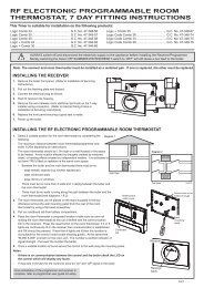
To light the boiler. refer to Frame 1<br />
1. CHECK THAT THE ELECTRICITY SUPPLY TO BOILER IS<br />
OFF.<br />
2. Set the mains mode knob control (D) to ‘Off’.<br />
3. Set the Domestic Hot Water temperature control (B) and<br />
Central <strong>Heating</strong> temperature control (C) to ‘max’.<br />
4. Set the preheat control (A) to ‘on’.<br />
5. Ensure that all hot water taps are turned off.<br />
6. Switch ON electricity to the boiler and check that all<br />
controls, e.g. timer and room thermostat, are ON (refer to<br />
mechanical timer instructions - Page 4).<br />
7. Set the mode knob control to winter ( ).<br />
The boiler will commence the ignition sequence, first supplying<br />
heat to preheat the domestic hot water and then to the central<br />
heating, if required.<br />
Note. In normal operation the boiler status display (E) will<br />
show codes:<br />
Standby - no demand for heat.<br />
CH being supplied.<br />
DHW being supplied.<br />
DHW preheat.<br />
<strong>Ideal</strong> stelrad group is a member of the Benchmark scheme and fully supports the aims of<br />
the programme. Benchmark has been introduced to improve the standards of installation and<br />
commissioning of central heating systems in the UK and to encourage the regular servicing of all<br />
central heating systems to ensure safety and efficiency.<br />
ThE BENChMaRK sERVICE INTERVaL RECORD MUsT BE COMpLETED aFTER EaCh sERVICE<br />
Boiler frost protection - boiler will fire if temperature is<br />
below 5 degrees C.<br />
During normal operation the burner on indicator (F) will remain<br />
illuminated when the burner is lit.<br />
Note: If the boiler fails to light after five attempts the fault code<br />
will be displayed.<br />
REsET pROCEDURE<br />
To reset boiler, turn the mode control knob (D) to reset position<br />
and immediately turn knob back to required setting. The boiler<br />
will repeat the ignition sequence. If the boiler still fails to light<br />
consult a Gas Safe Registered Engineer or in IE a Registered<br />
Gas Installer (RGII).<br />
All Gas Safe Register installers carry a Gas Safe Register ID card, and have a registration number. Both should be recorded in the<br />
Benchmark Commissioning Checklist. You can check your installer by calling Gas Safe Register direct on 0800 4085500.<br />
2 <strong>Independent</strong> - User’s
operation<br />
Winter conditions - i.e. Ch and DhW required.<br />
Ensure the mode knob control (D) is set to winter ( )<br />
The boiler will fire and supply heat to the radiators but will give<br />
priority to DHW on demand.<br />
The DHW preheat will operate as described under ‘Summer<br />
conditions’ during periods when there is no call for CH.<br />
summer conditions - i.e. DhW only required.<br />
Set the mode knob control to Summer ( ).<br />
Set the CH external controls to OFF.<br />
Preheat will operate with the preheat switch (A) set to ON.<br />
The boiler will fire periodically for a few seconds to maintain the<br />
DHW calorifier in a preheated condition. The average time period<br />
between firing is 90 minutes. This may vary considerably due to<br />
the surrounding ambient temperature of the boiler. The boiler will<br />
fire whenever there is a demand for DHW.<br />
The boiler preheat facility can be immobilised by turning the<br />
preheat switch (A) to OFF. This will stop the boiler operating<br />
for short periods. This facility is primarily provided for boiler<br />
installations in a sensitive area (i.e. bedroom etc.)<br />
note. The pump will operate briefly as a self-check once every 24<br />
hours, regardless of system demand.<br />
Control of water temperature<br />
Domestic hot Water<br />
The DHW temperature is limited by the boiler controls to<br />
64 o C maximum at low draw-off rate, adjustable via the DHW<br />
temperature control (B).<br />
Approx. flow temperatures for the boiler thermostat settings are:<br />
Knob setting Flow Temperature<br />
Minimum 40 o C (104 o F)<br />
Maximum 64 o C (147 o F)<br />
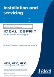
1 boiler ConTrols<br />
Legend<br />
a. Pre-heat On/Off<br />
B. DHW Temperature Control<br />
C. CH Temperature Control<br />
<strong>Independent</strong> - User’s<br />
G<br />
D. Mode Control<br />
E. Boiler Status<br />
F. Burner ‘on’ Indicator<br />
Due to system variations and seasonal temperature fluctuations<br />
DHW flow rates/temperature rise will vary, requiring adjustment<br />
at the draw off tap : the lower the rate the higher the temperature,<br />
and vice versa.<br />
Central heating<br />
The boiler controls the central heating radiator temperature to a<br />
maximum of 80 o C, adjustable via the CH temperature control (C).<br />
The <strong>Independent</strong> is a high efficiency combination boiler which is<br />
most efficient when operating in condensing mode.<br />
The boiler will operate in this mode if the CH temperature control<br />
(C) is set to the ‘e’ position (economy mode). This control should<br />
be set to maximum for very cold periods<br />
To shut down the boiler<br />
Set the mode knob control to OFF<br />
A B E F C J D<br />
To relight the boiler<br />
Repeat the procedure detailed in ‘To light the boiler’.<br />
Frost protection<br />
If no system frost protection is provided and frost is likely during<br />
a short absence from home, leave the heating controls (if fitted)<br />
at a reduced temperature setting. For longer periods, the entire<br />
system should be drained.<br />
If the system includes a frost thermostat then, during cold<br />
weather, the boiler should be turned OFF at the time switch (if<br />
fitted) ONLY. The mains supply should be left switched ON, with<br />
the boiler thermostat left in the normal running position.<br />
boiler overheat protection<br />
The boiler controls will shut down the boiler in the event of<br />
overheating. Should this occur, a fault code will be displayed.<br />
Refer to fault chart.<br />
Flame Failure<br />
Should this occur a fault code will be displayed. Refer to fault<br />
chart.<br />
H<br />
g. Pressure Gauge<br />
h. Condensate Drain<br />
J. Economy Mode<br />
continued . . . . . .<br />
3
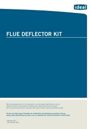
Loss of system water pressure<br />
The gauge (G) indicates the central heating system pressure. If<br />
the pressure is seen to fall below the original installation pressure<br />
of 1-2 bar over a period of time then a water leak may be<br />
indicated. In this event the re-pressurise the boiler. If unable to<br />
do so or if the pressure continues to drop a Gas Safe Registered<br />
Engineer or in IE a Registered Gas Installer (RGII) should be<br />
consulted.<br />
The boiler Will noT operaTe iF The pressure has<br />
reDuCeD To less Than 0.3 bar unDer This ConDiTion.<br />
5<br />
PRESSURE GAUGE<br />
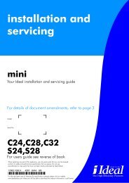
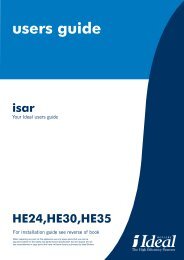
MEChaNICaL 24 hOUR TIMER<br />
3<br />
sETTINg Up<br />
The outer dial should be set to the current time. Rotate<br />
the dial slowly in a clockwise direction, until the correct<br />
hour is aligned with the arrow printed on the dial.<br />
Note that the outer dial is printed with the 24hr clock e.g.<br />
8.00am = 8 on the dial, 8.00pm = 20 on the dial.<br />
Do not attempt to rotate the dial in an anti-clockwise<br />
direction.<br />
pROgRaMMINg sWITChINg TIMEs<br />
Set tappets to outer edge for ON periods and set tappets<br />
to inner edge for OFF periods.<br />
The example shown has been set with 2 on periods.<br />
ON at 9.00am. OFF at 1.00pm. (13 hours)<br />
ON at 6.00pm. (18 hours) OFF at 10.00pm (22 hours)<br />
Manual OFF<br />
Manual ON<br />
Align current<br />
time to arrow<br />
4 <strong>Independent</strong> - User’s<br />
Timed<br />
Outer dial<br />
6<br />
7<br />
8<br />
5<br />
ON<br />
PERIOD<br />
MaNUaL sWITCh OpERaTION<br />
To set the timer for timed operation move the switch to the “TIMED” position.<br />
To set the timer to be continuously on, move the switch to the “MANUAL ON” position.<br />
To set the timer to be continuously off, move the switch to the “MANUAL OFF” position.<br />
Condensate Drain<br />
The condensate drain (H) must not be modified or blocked.<br />
Blockage of the condensate drain, caused by debris or<br />
freezing, can cause automatic shutdown of the boiler.<br />
If freezing is suspected and the pipe run is accessible an<br />
attempt may be made to free the obstruction by pouring<br />
hot water over the exposed pipe and clearing any blockage<br />
from the end of the pipe. If this fails to remedy the problem<br />
the assistance of a Gas Safe Registered Engineer or in IE a<br />
Registered Gas Installer (RGII) should be sought.<br />
escape of gas<br />
Should a gas leak or fault be suspected contact the National<br />
Gas Emergency Service without delay. Telephone 0800 111<br />
999<br />
Do NOT search for gas leaks with a naked flame.<br />
Cleaning<br />
For normal cleaning simply dust with a dry cloth.<br />
To remove stubborn marks and stains, wipe with a damp<br />
cloth and finish off with a dry cloth.<br />
Do noT use abrasive cleaning materials.<br />
Maintenance<br />
The appliance should be serviced at least once a year by<br />
a Gas Safe Registered Engineer or in IE a Registered Gas<br />
Installer (RGII).<br />
noTe<br />
If boiler does not light when in “timed on” or “manual on” position, increase temperature on room stat.<br />
3G9933<br />
9<br />
4<br />
10<br />
3<br />
11<br />
2<br />
12<br />
1<br />
GRASSLIN<br />
13<br />
24<br />
14<br />
23<br />
15<br />
22<br />
16<br />
21<br />
17<br />
20<br />
19<br />
18<br />
3G9994<br />
ON<br />
PERIOD
pOINTs FOR ThE BOILER UsER<br />
Note. In line with our current warranty policy we would ask that you check through the Troubleshooting guide to identify any problems<br />
external to the boiler prior to requesting a service engineers visit. Should the problem be found to be other than with the appliance we<br />
reserve the right to levy a charge for the visit, or for any pre-arranged visit where access is not gained by the engineer.<br />
TROUBLEshOOTINg<br />
NO hOT WaTER<br />
Check the mains switch (fused<br />
spur) is turned on and ensure<br />
switch mode control knob (D) is<br />
in the summer or winter position<br />
Is water coming out of the hot<br />
water tap when turned on?<br />
YES<br />
See boiler “Fault Codes”<br />
section. If ‘0’ is displayed then<br />
contact <strong>Ideal</strong> Customer Services<br />
Helpline if your appliance is<br />
under warranty or a Gas Safe<br />
Registered Engineer, in IE a<br />
Registered Gas Installer (RGII),<br />
if out of warranty<br />
Contact a Gas Safe Registered<br />
Engineer or in IE a Registered<br />
Gas Installer (RGII)<br />
<strong>Independent</strong> - User’s<br />
No<br />
OpERaTION MODEs<br />
DIspLay CODE ON BOILER DEsCRIpTION<br />
NO CENTRaL hEaTINg<br />
Check the mains switch (fused<br />
spur) is turned on and ensure<br />
switch mode control knob (D) is<br />
in the winter position<br />
Check the timer is in an “ON”<br />
position and the room thermostat<br />
is turned up<br />
Does the boiler operate and<br />
provide central heating?<br />
YES<br />
Check the time settings on the<br />
programmer are as you require<br />
and adjust if necessary<br />
No<br />
See boiler “Operation Modes” and<br />
“Fault Codes” section. If “0” is<br />
displayed then contact a Gas Safe<br />
Registered Engineer or in IE a<br />
Registered Gas Installer (RGII)<br />
NO hOT WaTER OR<br />
CENTRaL hEaTINg<br />
Check the fused spur is turned<br />
on and ensure switch mode<br />
control knob (D) is in the winter<br />
position<br />
Does the boiler have a display<br />
showing on the front control<br />
panel?<br />
YES<br />
See boiler “Operation Modes”<br />
and “Fault Codes” section<br />
Contact a Gas Safe Registered<br />
Engineer or in IE a Registered<br />
Gas Installer (RGII)<br />
The boiler is in standby mode awaiting either a central heating call or hot water demand.<br />
The boiler has a call for central heating but the appliance has reached the desired<br />
temperature set on the boiler.<br />
The boiler has a call for hot water but the appliance has reached the desired temperature set on<br />
the boiler.<br />
The boiler is operating in central heating mode.<br />
The boiler is operating in hot water mode.<br />
The boiler is operating in pre heat mode.<br />
The boiler is operating in frost mode.<br />
No<br />
continued . . . . . .<br />
5
FaULT CODEs<br />
DIspLay CODE ON BOILER DEsCRIpTION<br />
Outside Sensor Failure Reset the appliance - if the boiler fails to operate then please contact<br />
<strong>Ideal</strong> (if under warranty) or alternatively a Gas Safe Registered<br />
Engineer if outside of the warranty period. In IE contact a Registered<br />
Gas Installer (RGII).<br />
Low Mains Voltage Contact a qualified electrician or your electricity provider.<br />
Unconfigured PCB Unconfigured PCB. Please contact <strong>Ideal</strong> (if under warranty) or<br />
alternatively a Gas Safe Registered Engineer if outside of the warranty<br />
period. In IE contact a Registered Gas Installer (RGII).<br />
No Water Flow Thermistor<br />
Reset the appliance - if the boiler fails to operate then please contact<br />
<strong>Ideal</strong> (if under warranty) or alternatively a Gas Safe Registered<br />
Engineer if outside of the warranty period. In IE contact a Registered<br />
Gas Installer (RGII).<br />
5 Boiler Resets in 15 minutes 1. Turn power off and on at the fused spur.<br />
2. If the boiler fails to operate please contact <strong>Ideal</strong> (if under warranty)<br />
or alternatively a Gas Safe Registered Engineer if outside of the<br />
warranty period. In IE contact a Registered Gas Installer (RGII).<br />
False Flame Lockout Reset the appliance - if the boiler fails to operate then please contact<br />
<strong>Ideal</strong> (if under warranty) or alternatively a Gas Safe Registered<br />
Engineer if outside of the warranty period. In IE contact a Registered<br />
Gas Installer (RGII).<br />
BCC Activation Fault Reset the appliance - if the boiler fails to operate then please contact<br />
<strong>Ideal</strong> (if under warranty) or alternatively a Gas Safe Registered<br />
Engineer if outside of the warranty period. In IE contact a Registered<br />
Gas Installer (RGII).<br />
BCC Fault<br />
Low Water Pressure<br />
Flow Temperature Overheat<br />
No Water Flow<br />
aCTION<br />
Check system pressure is between 1 & 1.5bar on the pressure gauge.<br />
If the boiler fails to operate then please contact <strong>Ideal</strong> (if under warranty)<br />
or alternatively a Gas Safe Registered Engineer if outside of the<br />
warranty period. In IE contact a Registered Gas Installer (RGII).<br />
Flame Loss 1. Check other gas appliances in the house are working to confirm a<br />
supply is present in the property.<br />
2. If other appliances do not work or there are no other appliances,<br />
check the gas supply is on at the meter and/or pre payment meter<br />
has credit. If the boiler fails to operate then please contact <strong>Ideal</strong> (if<br />
under warranty) or alternatively a Gas Safe Registered Engineer<br />
if outside of the warranty period. In IE contact a Registered Gas<br />
Installer (RGII).<br />
Fan Fault Reset the appliance - if the boiler fails to operate then please contact<br />
<strong>Ideal</strong> (if under warranty) or alternatively a Gas Safe Registered<br />
Engineer if outside of the warranty period. In IE contact a Registered<br />
Gas Installer (RGII).<br />
Flow Thermistor Reset the appliance - if the boiler fails to operate then please contact<br />
<strong>Ideal</strong> (if under warranty) or alternatively a Gas Safe Registered<br />
Engineer if outside of the warranty period. In IE contact a Registered<br />
Gas Installer (RGII).<br />
Return Thermistor Reset the appliance - if the boiler fails to operate then please contact<br />
<strong>Ideal</strong> (if under warranty) or alternatively a Gas Safe Registered<br />
Engineer if outside of the warranty period. In IE contact a Registered<br />
Gas Installer (RGII).<br />
6 <strong>Independent</strong> - User’s