Harmonic Filter Design for Hvdc Lines Using Matlab
International Journal of Computational Engineering Research(IJCER) is an intentional online Journal in English monthly publishing journal. This Journal publish original research work that contributes significantly to further the scientific knowledge in engineering and Technology.
International Journal of Computational Engineering Research(IJCER) is an intentional online Journal in English monthly publishing journal. This Journal publish original research work that contributes significantly to further the scientific knowledge in engineering and Technology.

You also want an ePaper? Increase the reach of your titles
YUMPU automatically turns print PDFs into web optimized ePapers that Google loves.
International Journal of Computational Engineering Research||Vol, 03||Issue, 11||<br />
<strong>Harmonic</strong> <strong>Filter</strong> <strong>Design</strong> <strong>for</strong> <strong>Hvdc</strong> <strong>Lines</strong> <strong>Using</strong> <strong>Matlab</strong><br />
1, P.Kumar , 2, P.Prakash<br />
1, Power Systems Division Assistant Professor DEEE, P.A. College of Engineering and Technology, Pollachi<br />
2 VLSI <strong>Design</strong>,, Assistant Professor DEEE, P.A. College of Engineering and Technology, Pollachi<br />
ABSTRACT: This paper presents harmonic filter design <strong>for</strong> HVDC lines using MATLAB version<br />
R2009a.Non-linear devices such as power electronics converters can inject harmonics alternating<br />
currents (AC) in the electrical power system. The number of sensitive loads that require ideal sinusoidal<br />
supply voltage <strong>for</strong> their proper operation has been increasing. To maintain the quality limits proposed<br />
by standards to protect the sensitive loads, it is necessary to include some <strong>for</strong>m of the filtering device to<br />
the power system. <strong>Harmonic</strong>s also increases overall reactive power demanded equivalent load. This<br />
paper deals with the design of three phase filter banks connected in parallel to achieve optimal control<br />
<strong>for</strong> harmonic elevation problems.<br />
KEYWORDS: harmonic filter, sensitive loads, reactive power, three phase filter banks, optimal<br />
control, harmonic elevation problems.<br />
I INTRODUCTION<br />
Advancement in technology of semiconductor devices has led to a revolution in electronic technology<br />
over the past decade. However rise in the power quality (PQ) problem is due to power equipments which<br />
include adjustable-speed motor drives (ASDs), electronic power supplies, direct current (DC) motor drives,<br />
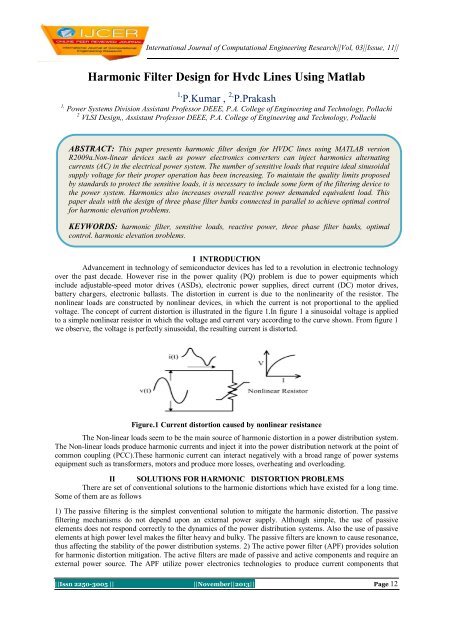
battery chargers, electronic ballasts. The distortion in current is due to the nonlinearity of the resistor. The<br />
nonlinear loads are constructed by nonlinear devices, in which the current is not proportional to the applied<br />
voltage. The concept of current distortion is illustrated in the figure 1.In figure 1 a sinusoidal voltage is applied<br />
to a simple nonlinear resistor in which the voltage and current vary according to the curve shown. From figure 1<br />
we observe, the voltage is perfectly sinusoidal, the resulting current is distorted.<br />
Figure.1 Current distortion caused by nonlinear resistance<br />
The Non-linear loads seem to be the main source of harmonic distortion in a power distribution system.<br />
The Non-linear loads produce harmonic currents and inject it into the power distribution network at the point of<br />
common coupling (PCC).These harmonic current can interact negatively with a broad range of power systems<br />
equipment such as trans<strong>for</strong>mers, motors and produce more losses, overheating and overloading.<br />
II SOLUTIONS FOR HARMONIC DISTORTION PROBLEMS<br />
There are set of conventional solutions to the harmonic distortions which have existed <strong>for</strong> a long time.<br />
Some of them are as follows<br />
1) The passive filtering is the simplest conventional solution to mitigate the harmonic distortion. The passive<br />
filtering mechanisms do not depend upon an external power supply. Although simple, the use of passive<br />
elements does not respond correctly to the dynamics of the power distribution systems. Also the use of passive<br />
elements at high power level makes the filter heavy and bulky. The passive filters are known to cause resonance,<br />
thus affecting the stability of the power distribution systems. 2) The active power filter (APF) provides solution<br />
<strong>for</strong> harmonic distortion mitigation. The active filters are made of passive and active components and require an<br />
external power source. The APF utilize power electronics technologies to produce current components that<br />
||Issn 2250-3005 || ||November||2013|| Page 12
<strong>Harmonic</strong> <strong>Filter</strong> <strong>Design</strong> For…<br />
cancel the harmonic currents from the non-linear loads. With the APF the switching frequency noise requires<br />
additional filtering to prevent with other sensitive equipments.<br />
3) The passive high-pass filter (HPF) used in addition to the conventional APF <strong>for</strong> mitigating harmonics. This<br />
combination is known to be hybrid APF.The main objective of hybrid APF is to improve the filtering<br />
per<strong>for</strong>mance of high-order harmonics while providing a cost-effective low order harmonic mitigation.<br />
III MATHEMATICAL ANALYSIS OF HARMONICS<br />
3.1 TOTAL HARMONIC DISTORTION<br />
The basic parameter that is used <strong>for</strong> the harmonic analysis is the total harmonic distortion (THD).The<br />
total harmonic distortion (THD) gives the common measurement indices of harmonic distortion.THD applies to<br />
both current and voltage and is defined as the root-mean-square (rms) value of the harmonics divided by the rms<br />
value of the fundamental and then multiplied by 100%.The THD is given by the following equation.<br />
Where<br />
THD<br />
<br />
h max<br />
<br />
h 1<br />
M<br />
M<br />
1<br />
2<br />
h<br />
100<br />
M is the rms value of harmonic component h of the quantity M .<br />
h<br />
THD of the current varies from a few percent to more than 100%.THD of the voltage is usually less<br />
than 5%.Voltage THDs below 5% are widely considered to be acceptable, while values above 10% are<br />
definitely unacceptable and will cause problems <strong>for</strong> sensitive equipment and loads.The biggest problem with<br />
harmonics is voltage wave<strong>for</strong>m distortion. We can calculate a relation between the fundamental and distorted<br />
wave<strong>for</strong>ms by finding the sum of the squares of all harmonics generated by a single load, and then dividing this<br />
number by the nominal 50/60 Hz wave<strong>for</strong>m value. We do this by a mathematical calculation known as Fast<br />
Fourier Trans<strong>for</strong>m (FFT) Theorem. This calculation method determines the total harmonics distortion (THD)<br />
contained within a nonlinear current or voltage wave<strong>for</strong>m.<br />
3.2 FOURIER SERIES<br />
Fourier series are used in the analysis of periodic functions or periodic signals into the sum of<br />
oscillating function called sines and cosines. Many of the phenomena studied in engineering and science are<br />
periodic in nature eg. the current and voltage in an alternating current circuit. These periodic functions can be<br />
analyzed into their constituent components (fundamentals and harmonics) by a process called Fourier analysis.<br />
By definition, a periodic function, f(t) is that where f(t) = f(t+T). This function can be represented by a<br />
trigonometric series of elements consisting of a DC component and other elements with frequencies comprising<br />
the fundamental component and its integer multiple frequencies. This applies if the following so-called Dirichlet<br />
conditions are met:<br />
If a discontinuous function, f(t) has a finite number of discontinuities over the period T<br />
If f(t) has a finite mean value over the period T<br />
If f(t) has a finite number of positive and negative maximum values<br />
The expression <strong>for</strong> Fourier series expansion is given as follows,<br />
<br />
a<br />
0<br />
ft ) [ a cos<br />
n<br />
0 n<br />
0<br />
2<br />
Where 2<br />
0<br />
<br />
n 1<br />
/ T<br />
n<br />
t b sin n<br />
t ]<br />
We can further simplify equation (1), we get<br />
Where<br />
<br />
c sin<br />
0 n<br />
n 1<br />
<br />
n<br />
<br />
(1)<br />
(2)<br />
f ( t ) c<br />
n t <br />
(3)<br />
a<br />
0<br />
2 2<br />
c , c a b , tan<br />
0 n<br />
n n n<br />
2<br />
0<br />
1<br />
b<br />
<br />
a<br />
n<br />
n<br />
<br />
<br />
<br />
||Issn 2250-3005 || ||November||2013|| Page 13
th<br />
n<br />
order harmonic of the periodic function<br />
n<br />
0<br />
c magnitude of the DC component<br />
0<br />
and c n<br />
n<br />
magnitude and phase angle of the n<br />
th<br />
harmonic component<br />
<strong>Harmonic</strong> <strong>Filter</strong> <strong>Design</strong> For…<br />
The component with n =1 is the fundamental component. Magnitude and phase angle of each harmonic<br />
determine the resultant wave<strong>for</strong>m f (t).<br />
The equation (3) can be written in complex <strong>for</strong>m as,<br />
Where n=0, 1,<br />
2<br />
<br />
<br />
n 1<br />
n<br />
jn <br />
o t<br />
f ( t ) c e<br />
(4)<br />
c<br />
n<br />
<br />
/ 2<br />
1 T <br />
T<br />
T / 2<br />
f<br />
( t ) e<br />
jn <br />
0 t<br />
dt<br />
(5)<br />
The main source of harmonics in power system is the static power converter. Under ideal operation condition,<br />
harmonics generated by a p pulse power converter are characterized by,<br />
I<br />
1<br />
I n<br />
, and n pl 1 (6)<br />
n<br />
where n stand <strong>for</strong> the characteristic harmonics of the load; l=1, 2… and p is an integer multiple of six.<br />
The figure below gives the example of harmonic spectrum<br />
Figure 2. Example of harmonics spectrum<br />
IV SIMULATION AND RESULTS<br />
The figure 3 represents the simulink model of proposed system created in MATLAB.The three phase<br />
harmonic filters are connected between the buses B1 and B2 through breaker. For analysis of the harmonics two<br />
cases were taken. Case 1 with the three phase harmonics filters connected to the lines and the case 2 with the<br />
harmonic filters not connected to the lines.<br />
||Issn 2250-3005 || ||November||2013|| Page 14
<strong>Harmonic</strong> <strong>Filter</strong> <strong>Design</strong> For…<br />
Figure 3. Simulink model of the proposed system<br />
Three-phase harmonic filters are shunt elements that are used in power systems <strong>for</strong> decreasing voltage<br />
distortion and <strong>for</strong> power factor correction. Nonlinear elements such as power electronic converters generate<br />
harmonic currents or harmonic voltages, which are injected into power system. The resulting distorted currents<br />
flowing through system impedance produce harmonic voltage distortion. <strong>Harmonic</strong> filters reduce distortion by<br />
diverting harmonic currents in low impedance paths. <strong>Harmonic</strong> filters are designed to be capacitive at<br />
fundamental frequency, so that they are used <strong>for</strong> producing reactive power required by converters and <strong>for</strong> power<br />
factor correction.The HVDC (High Voltage Direct Current) rectifier is built up from two 6-pulse thyristor<br />
bridges connected in series. The converter is connected to the system with a 1200-MVA three phase trans<strong>for</strong>mer<br />
(three windings).A 1000-MW resistive load is connected to the DC side through a 0.5 H smoothing reactor. The<br />
filters are made of the following four components of the powerlib/Elements library:<br />
1. One capacitor banks (C1) of 150 Mvar modeled by a “Three-Phase <strong>Harmonic</strong> <strong>Filter</strong>s “are used in HVDC line.<br />
(i).One C-type high-pass filter to the 3 rd (F1) of 150<br />
Mvar<br />
(ii).One double-tuned filter 11 th /13 th (F2) of 150 Mvar<br />
(iii).One high-pass filter tuned to the 24 th (F3) of 150 Mvar.<br />
In order to achieve an acceptable distortion, several banks of filters of different types are usually<br />
connected in parallel. The combinations of different banks are derived from basic filters Butterworth Chebyshev<br />
and Cauer filters. The most commonly used filter types are<br />
1. Band-pass filters, which are used to filter lowest order harmonics such as 5 th ,7 th ,11 th ,13 th etc.Band-pass<br />
filters can be tuned at a single frequency(single tuned filter) or at two frequencies(double-tuned filter)<br />
2. High-pass filters, which are used to filter high-order harmonics and cover a wide range of frequencies. A<br />
special type of high-pass filter, the C-type high-pass filter, is used to provide reactive power and avoid parallel<br />
resonances. It also allows filtering low order harmonics (such as 3 rd ), while keeping zero losses at fundamental<br />
frequency.<br />
The figure below shows the different types of three-phase RLC harmonic filter.<br />
Figure 4. Different types of three-phase RLC harmonic filter<br />
||Issn 2250-3005 || ||November||2013|| Page 15
<strong>Harmonic</strong> <strong>Filter</strong> <strong>Design</strong> For…<br />
The simulink model of the proposed system is given in figure 2.The power converter usually act as nonlinear<br />
source injecting harmonics into the system. The three phase harmonic filter is installed between the buses B1<br />
and B2.<br />
Figure 5. Three phase voltage at the bus B1 without harmonic filter<br />
Figure 6. Three phase voltage at the bus B1 with harmonic filter<br />
Figures 4 and 5 gives the simulation results of the three phase voltage at the bus B1 with and without<br />
harmonic filters. From figure 4 we observe that in the absence of three phase harmonic filters the three phase<br />
voltage at the bus B1 getting distorted due to the harmonics injected by the rectifier, which is the non-linear load<br />
in this case.<br />
Figure 7. Three phase current at the bus B1 without harmonic filter<br />
Figure 8. Three phase current at the bus B2 without harmonic filter<br />
||Issn 2250-3005 || ||November||2013|| Page 16
<strong>Harmonic</strong> <strong>Filter</strong> <strong>Design</strong> For…<br />
Figure 9. Three phase current at the bus B1 with harmonic filter<br />
Figure 10. Three phase current at the bus B2 with harmonic filter<br />
Figures 6 and 7 gives the simulation results of three phase currents at the buses B1 and B2 without<br />
harmonic filters. Figures 8 and 9 gives the simulation results of three phase currents at the buses B1 and B2 with<br />
harmonic filters. On comparison of figures 6,7 and 8,9 we observe that in the absence of three phase harmonic<br />
filters the three phase currents at the bus B1 and B2 getting distorted due to the harmonics injected by the nonlinear<br />
load.<br />
Figure 11. <strong>Harmonic</strong> spectrum of three-phase currents at bus B2 without harmonic filter<br />
Figure 12. <strong>Harmonic</strong> order of three-phase currents at bus B2 without harmonic filter<br />
||Issn 2250-3005 || ||November||2013|| Page 17
<strong>Harmonic</strong> <strong>Filter</strong> <strong>Design</strong> For…<br />
Figure 13. <strong>Harmonic</strong> spectrum of three-phase currents at bus B2 with harmonic filter<br />
Figure 14. <strong>Harmonic</strong> order of three-phase currents at bus B2 with harmonic filter<br />
On comparison on figures 10, 11 with figures 11, 12 we observe that the total harmonic reduction<br />
(THD) was considerably reduced from 12.59% <strong>for</strong> the case without harmonic filters to 0.70% <strong>for</strong> the case with<br />
harmonic filters. The simulation is per<strong>for</strong>med <strong>for</strong> the test case with alpha 19 degree .Simulations can be<br />
per<strong>for</strong>med <strong>for</strong> various values of alpha and the impact on the DC level and on generated harmonics can be noted.<br />
V CONCLUSION<br />
There will be an increasing economical impact on the operation of electrical power system due to<br />
losses in the system.In this study the HVDC model in MATLAB/SIMULINK is used with different three phase<br />
filter banks to reduce the distortion and to increase the power quality of the system. Three phase harmonic filter<br />
used in this work <strong>for</strong> decreasing the voltage distortion and <strong>for</strong> power factor correction. The focus of this work is<br />
to have economical impact of the electrical power system through harmonics, distortion reduction and to<br />
increase the power quality of the system.<br />
VI SCOPE OF FUTURE WORK<br />
This is work can be extended in future with different filter combinations <strong>for</strong> decreasing the harmonics.<br />
Advanced modifications can be imparted to this filter design to address various power quality issues and to<br />
provide the end users with reliable source of power.<br />
REFERENCES<br />
[1] Himabindu. T, Jayaprakash, “Per<strong>for</strong>mance of single phase shunt active filter based on P-Q technique using matlab/simulink”,<br />
International Journal of Engineering Research and Technology, vol.1, Issue 9, November 2012.<br />
[2] P.Thirumoorthi, Jyothis Francis and N.Yadaiah, “Power conditioning in battery chargers using shunt active power filter through<br />
neural network”, International Journal of Advances in Engineering & Technology, March 2012.<br />
[3] R.Sriranjani and S.Jayalalitha, “Investigation the per<strong>for</strong>mance of the various types of harmonic filters”, World Applied Sciences<br />
Journal 17(5):643-650 2012.<br />
[4] C. Nalini Kiran, Subhransu Sekhar Dash, and S. Prema Latha, “A Few Aspects of Power Quality Improvement <strong>Using</strong> Shunt<br />
Active Power <strong>Filter</strong>,” International Journal of Scientific & Engineering Research,vol.2, Issue 5, May 2011.<br />
||Issn 2250-3005 || ||November||2013|| Page 18
<strong>Harmonic</strong> <strong>Filter</strong> <strong>Design</strong> For…<br />
[5] Shu,Z.,S.Xie and Q.Li,2011, “Single phase back to back converter <strong>for</strong> active power balancing, reactive power compensation and<br />
harmonic filtering in traction power system”,IEEE Trans.Power Electronics,26:2.<br />
[6] S. Mikkili and A. K. Panda, “APF <strong>for</strong> mitigation of current harmonics with p-q and id-iq control strategies using pi controller,”<br />
Journal of Trends in Electrical Engineering, Vol. 1, No. 1, pp. 1-11, May 2011.<br />
[7] Seema P. Diwan, Pradeep Diwan, a.P Vaidya,"Simulation Studies of Single phase Shunt Active <strong>Filter</strong> with the DC Capacitor<br />
Voltage Control,"IEEE,2011.<br />
[8] Attia, A. H., El-Metwally, M. and Fahmy O.M., “<strong>Harmonic</strong> distortion effects and mitigation in distribution systems”, Journal of<br />
American Science, 2010 vol.6, no.10, pp.173-183.<br />
[9] Rahmani, S., Mendalek, N., and Al-Haddad, K.,"Experimental <strong>Design</strong> of a Nonlinear Control Technique <strong>for</strong> Three-Phase Shunt<br />
Active Power <strong>Filter</strong>", IEEE Transactions on Industrial Electronics, Volume 57,No. 10, pp.3364-3375, 2010.<br />
[10] Aaron Vander Meulen and John Maurin, Application Engineers, Current source inverter vs.Voltage source inverter topology.<br />
August 2010.<br />
[11] Chen, C.I., Chang, G.W., Hong, R.C., and Li, H.M.,"Extend Real Model of Kalman <strong>Filter</strong> <strong>for</strong> Time-Varying <strong>Harmonic</strong>s<br />
Estimation", IEEE Transactions on Power<br />
Delivery, Volume 25, No. 1, pp. 17-26, 2010.<br />
[12] Jaume Miret, Miguel Castilla, Jose Matas, Josep M.Guerrero, Juan C.Vasquez, “Selective harmonic-compensation control <strong>for</strong><br />
single phase active power filter with high harmonic rejection”,IEEE transactions on industrial electronics,vol.56,no.8,August<br />
2009.<br />
[13] P. Kumar and A.Mahajan, “Soft computing techniques <strong>for</strong> the control of an active power filter,” IEEE Trans. Power<br />
Del.,vol.24,no.,pp.452-461,Jan 2009.<br />
[14] L.Asiminoaei, F.Blaabjerg, S.Hansen, and P.Thogersen, “Adaptive compensation of reactive power with shunt active power<br />
filters, IEEE Trans.Ind.Appl., vol.44, no.3, pp.867877,May/Jun 2008.<br />
[15] Abdusalam, M., P. Poure and S.Saadate, 2008. “Hardware implementation of a three phase active filter system with harmonic<br />
isolation based on self tuning filter”, IEEE.<br />
[16] <strong>Harmonic</strong>s and Power System, Francisco C. De LA ROSA, Distribution Control System, Inc, Hazelwood, Massouri, USA.<br />
[17] Basic Electronics Eighth Edition, by Bernard Grob.<br />
||Issn 2250-3005 || ||November||2013|| Page 19