

308655J - 10:1 Fire-Ball 425 Pump - US English - Graco Inc.
308655J - 10:1 Fire-Ball 425 Pump - US English - Graco Inc.
308655J - 10:1 Fire-Ball 425 Pump - US English - Graco Inc.

You also want an ePaper? Increase the reach of your titles
YUMPU automatically turns print PDFs into web optimized ePapers that Google loves.
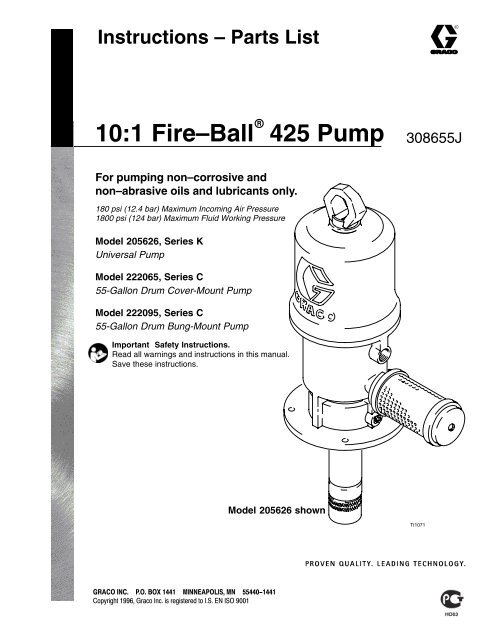
Instructions – Parts List<br />
<strong>10</strong>:1 <strong>Fire</strong>–<strong>Ball</strong> <strong>425</strong> <strong>Pump</strong><br />
<strong>308655J</strong><br />
For pumping non–corrosive and<br />
non–abrasive oils and lubricants only.<br />
180 psi (12.4 bar) Maximum <strong>Inc</strong>oming Air Pressure<br />
1800 psi (124 bar) Maximum Fluid Working Pressure<br />
Model 205626, Series K<br />
Universal <strong>Pump</strong><br />
Model 222065, Series C<br />
55-Gallon Drum Cover-Mount <strong>Pump</strong><br />
Model 222095, Series C<br />
55-Gallon Drum Bung-Mount <strong>Pump</strong><br />
Important Safety Instructions.<br />
Read all warnings and instructions in this manual.<br />
Save these instructions.<br />
Model 205626 shown<br />
TI<strong>10</strong>71
Table of Contents<br />
Warnings . . . . . . . . . . . . . . . . . . . . . . . . . . . . . . . . . . . . . . 2<br />
Installation . . . . . . . . . . . . . . . . . . . . . . . . . . . . . . . . . . . . . 4<br />
Parts Drawing . . . . . . . . . . . . . . . . . . . . . . . . . . . . . . . . . 15<br />
Dimensions . . . . . . . . . . . . . . . . . . . . . . . . . . . . . . . . . . . 16<br />
Operation . . . . . . . . . . . . . . . . . . . . . . . . . . . . . . . . . . . . . 7 Mounting Hole Layout . . . . . . . . . . . . . . . . . . . . . . . . . . 16<br />
Troubleshooting . . . . . . . . . . . . . . . . . . . . . . . . . . . . . . . . 8 Technical Data . . . . . . . . . . . . . . . . . . . . . . . . . . . . . . . . 16<br />
Air Motor and Throat Service . . . . . . . . . . . . . . . . . . . . . 9 Performance Chart . . . . . . . . . . . . . . . . . . . . . . . . . . . . 17<br />
Displacement <strong>Pump</strong> Service . . . . . . . . . . . . . . . . . . . . 13 Warranty . . . . . . . . . . . . . . . . . . . . . . . . . . . . . . . . . . . . . 18<br />
Parts List . . . . . . . . . . . . . . . . . . . . . . . . . . . . . . . . . . . . . 14 <strong>Graco</strong> Phone Number . . . . . . . . . . . . . . . . . . . . . . . . . . 18<br />
Symbols<br />
Warning Symbol<br />
WARNING<br />
This symbol alerts you to the possibility of serious<br />
injury or death if you do not follow the instructions.<br />
Caution Symbol<br />
CAUTION<br />
This symbol alerts you to the possibility of damage to<br />
or destruction of equipment if you do not follow the<br />
instructions.<br />
EQUIPMENT MIS<strong>US</strong>E HAZARD<br />
WARNING<br />
Equipment misuse can cause the equipment to rupture or malfunction and result in serious injury.<br />
<br />
<br />
<br />
<br />
<br />
<br />
<br />
<br />
<br />
<br />
<br />
<br />
This equipment is for professional use only.<br />
Read all instruction manuals, tags, and labels before you operate this equipment.<br />
Use the equipment only for its intended purpose. If you are not sure, call your <strong>Graco</strong> distributor.<br />
Do not alter or modify this equipment.<br />
Check equipment daily. Repair or replace worn or damaged parts immediately.<br />
Do not exceed the maximum working pressure stated on the equipment or in the Technical Data<br />
for your equipment. Do not exceed the maximum working pressure of the lowest rated component<br />
in your system.<br />
Use fluids and solvents which are compatible with the equipment wetted parts. Refer to the<br />
Technical Data section of all equipment manuals. Read the fluid and solvent manufacturer’s<br />
warnings.<br />
Do not use 1,1,1–trichloroethane, methylene chloride, other halogenated hydrocarbon solvents or<br />
fluids that contain such solvents in pressurized aluminum equipment. Such use could result in a<br />
chemical reaction, with the possibility of explosion.<br />
Handle hoses carefully. Do not pull on hoses to move equipment.<br />
Route hoses away from traffic areas, sharp edges, moving parts, and hot surfaces. Do not<br />
expose <strong>Graco</strong> hoses to temperatures above 82C (180F) or below –40C (–40F).<br />
Do not lift pressurized equipment.<br />
Comply with all applicable local, state, and national fire, electrical, and safety regulations.<br />
2 <strong>308655J</strong>
WARNING<br />
SKIN INJECTION HAZARD<br />
Fluid from the dispensing valve, leaks, or ruptured components can inject fluid into your body and<br />
cause extremely serious injury, including the need for amputation. Fluid splashed in the eyes or on<br />
the skin can also cause serious injury.<br />
<br />
<br />
<br />
<br />
<br />
<br />
<br />
Fluid injected into the skin may look like just a cut, but it is a serious injury. Get immediate<br />
surgical treatment.<br />
Do not point the dispensing valve at anyone or at any part of the body.<br />
Do not put your hand or fingers over the end of the dispensing valve.<br />
Do not stop or deflect leaks with your hand, body, glove or rag.<br />
Use only extensions and no-drip tips that are designed for use with your dispensing valve.<br />
Tighten all fluid connections before you operate this equipment.<br />
Check the hoses, tubes, and couplings daily. Replace worn or damaged parts immediately. Do<br />
not repair high pressure couplings; you must replace the entire hose.<br />
HAZARDO<strong>US</strong> FLUIDS<br />
Improper handling of hazardous fluids or inhaling toxic fumes can cause extremely serious injury,<br />
even death, due to splashing in the eyes, ingestion, or bodily contamination.<br />
<br />
<br />
<br />
Know the specific hazards of the fluid you are using.<br />
Store hazardous fluid in an approved container. Dispose of hazardous fluid according to all local,<br />
state, and national guidelines.<br />
Always wear protective eyewear, gloves, clothing, and respirator as recommended by the fluid<br />
and solvent manufacturer.<br />
FIRE AND EXPLOSION HAZARD<br />
Improper grounding, poor ventilation, open flames or sparks can cause a hazardous condition and<br />
result in a fire or explosion and serious injury.<br />
Ground the equipment. Refer to Grounding on page 6.<br />
<br />
<br />
<br />
If there is any static sparking or you feel an electric shock while you use this equipment, stop<br />
dispensing immediately. Do not use the equipment until you identify and correct the problem.<br />
Provide fresh air ventilation to avoid the buildup of flammable fumes from solvents or the fluid<br />
being dispensed.<br />
Do not smoke in the dispensing area.<br />
MOVING PARTS HAZARD<br />
Moving parts can pinch or amputate your fingers.<br />
<br />
<br />
Keep clear of all moving parts when you start or operate the pump.<br />
Before you service this equipment, follow the Pressure Relief Procedure on page 7 to prevent<br />
the equipment from starting unexpectedly.<br />
<strong>308655J</strong> 3
Installation<br />
The typical installation shown in Fig.1 is only a guide to<br />
help you select and install a pump; it is not an actual<br />
system design. Contact your <strong>Graco</strong> distributor for<br />
assistance in designing a system to suit your needs.<br />
CAUTION<br />
Always mount the pump firmly to a bracket or a<br />
tank cover. Never operate the pump while it is not<br />
mounted. Such use could damage the pump and<br />
fittings.<br />
G<br />
C<br />
A<br />
A<br />
N<br />
D<br />
A<br />
E<br />
R<br />
K<br />
H P J<br />
B<br />
Z<br />
F<br />
Y<br />
DETAIL A<br />
L<br />
TI0890<br />
S<br />
T<br />
M<br />
For Portable Applications<br />
KEY<br />
A Bleed-type master air valve<br />
(required, Part No. <strong>10</strong>7142)<br />
B Air line filter<br />
C Air regulator and gauge<br />
D <strong>Pump</strong> runaway valve<br />
E Air inlet<br />
F <strong>Ball</strong> valve (for releasing collected moisture)<br />
G <strong>Pump</strong><br />
H Drain valve (required, Part No. 2<strong>10</strong>658)<br />
J Dispensing valve (model 222411 shown)<br />
K Thermal relief kit (required, Part No. 240429)<br />
L Male quick-disconnect fitting<br />
M Female quick-disconnect coupler<br />
N Air line lubricator<br />
P Fluid hose<br />
R Electrically conductive air hose (218093 shown)<br />
Use at least 1/2 in. (13 mm) ID to supply an adequate volume<br />
of air to the air motor.<br />
S Fluid inlet<br />
T Wall-mounting bracket (Part No. 238245)<br />
Y Ground wire (required, Part No. 222011)<br />
Z Muffler<br />
Fig. 1<br />
06038<br />
4 <strong>308655J</strong>
Installation<br />
System Accessories<br />
CAUTION<br />
Do not hang the air accessories directly on the air<br />
inlet (E). The fittings are not strong enough to<br />
support the accessories and may cause one or<br />
more to break. Provide a bracket on which to<br />
mount the accessories.<br />
NOTE: Install the following accessories in the order<br />
shown in Fig. 1.<br />
WARNING<br />
Four accessories are required in your system: an<br />
air shut-off valve/air bleed device, fluid drain valve,<br />
thermal relief kit, and ground wire. These accessories<br />
help reduce the risk of serious bodily injury<br />
including fluid injection, splashing in the eyes or on<br />
the skin, injury from moving parts if you are adjusting<br />
or repairing the pump, and explosion from<br />
static sparking.<br />
The air bleed device relieves air trapped between it<br />
and the air motor after the air supply is shut off.<br />
Trapped air can cause the air motor to cycle unexpectedly,<br />
causing serious bodily injury if you are<br />
adjusting or repairing the pump. Use either a<br />
bleed-type master air valve (A) or a quick-disconnect<br />
coupler (M) and fitting (L). Install near the<br />
pump air inlet, within easy reach of the pump.<br />
<br />
<br />
<br />
<br />
<br />
<br />
Install an air line filter (B) to remove harmful dirt<br />
and contaminants from your compressed air supply.<br />
Install a bleed-type master air valve (A) to isolate<br />
the accessories for servicing. See Fig. 1. To order<br />
a bleed-type master air valve, order Part No.<br />
<strong>10</strong>7142.<br />
As an alternative to a bleed-type master air valve,<br />
you can install an air line quick disconnect coupler<br />
(M) and fitting (L) to serve as an air-bleed device.<br />
See Detail A in Fig. 1.<br />
Install a ball valve (F), at the end of a line drop, as<br />
shown in Fig. 1, for releasing moisture that collects<br />
in the line.<br />
Install a drain valve (H) near the pump fluid outlet to<br />
relieve fluid pressure in the hoses and gun when<br />
opened. To order a fluid drain valve, order Part No.<br />
2<strong>10</strong>658.<br />
Install a pump runaway valve (D) to shut off the air<br />
to the pump if the pump accelerates beyond the<br />
pre-adjusted setting, which can be caused by a<br />
depleted fluid supply. A pump that runs too fast<br />
can be seriously damaged. To order a 3/4-in. npt(f)<br />
inlet and outlet pump runaway valve, order Part No.<br />
215362.<br />
Install a thermal relief kit (K) on the dispensing<br />
valve side of the pump. To order a 1600 psi<br />
(1<strong>10</strong> bar) thermal relief kit, order Part No. 240429.<br />
<br />
<br />
<br />
The fluid drain valve (H) assists in relieving fluid<br />
pressure in the displacement pump, hoses, and<br />
dispensing valve. Triggering the valve to relieve<br />
pressure may not be sufficient.<br />
The thermal relief kit assists in relieving pressure in<br />
the pump, hose, and dispensing valve due to heat<br />
expansion.<br />
The ground wire reduces the risk of static sparking.<br />
Screw the muffler (5) into the 3/4-in. npt muffler<br />
port, and tighten it using a wrench on the flats of<br />
the muffler near the male threads.<br />
Install an air line lubricator (N) for automatic air<br />
motor lubrication.<br />
Install the air regulator (C) to control pump speed<br />
and pressure.<br />
<br />
Install a suitable fluid hose (P) and dispensing<br />
valve (J).<br />
Wall Mount<br />
The pump shown in Fig. 1 is a wall-mounted universal<br />
pump, Model 205626. To order the wall-mounting<br />
bracket shown, order Part No. 238245.<br />
Cover Mount<br />
<strong>Pump</strong> Model 222065 is designed for mounting directly<br />
on a 55-gallon drum cover. When the pump is<br />
mounted to a closed-head drum, be sure you loosen<br />
the vent plug on the drum cover to prevent a vacuum<br />
in the drum. For cover mounting, see the Mounting<br />
Hole Layout on page 16.<br />
Bung Mount<br />
<strong>Pump</strong> model 222095 is designed for bung mounting on<br />
a 55-gallon drum. The bung adapter (153) is shown in<br />
the Parts Drawing on page 15.<br />
<strong>308655J</strong> 5
Installation<br />
Grounding<br />
Proper grounding is an essential part of maintaining a<br />
safe system.<br />
To reduce the risk of static sparking, ground the pump.<br />
Check your local electrical code for detailed grounding<br />
instructions for your area and type of equipment. Be<br />
sure to ground this equipment:<br />
To ground the pump, remove the ground screw (Z)<br />
and insert through the eye of the ring terminal at end of<br />
the ground wire (Y). Fasten the ground screw back onto<br />
the pump and tighten securely. Connect the other end of<br />
the ground wire to a true earth ground. See Fig. 2. To<br />
order a ground wire and clamp, order Part No. 222011.<br />
<br />
<br />
<br />
<strong>Pump</strong>: Use a ground wire and clamp as shown in<br />
Fig. 2.<br />
Air and Fluid hoses: Use only electrically conductive<br />
hoses.<br />
Air compressor: Follow the manufacturer’s recommendations.<br />
Y<br />
<br />
<br />
Fluid supply container: Follow the local code.<br />
Object being lubricated: Follow the local code.<br />
Z<br />
<br />
To maintain grounding continuity when flushing or<br />
relieving pressure, always hold a metal part of the<br />
valve firmly to the side of a grounded metal pail,<br />
then trigger the valve.<br />
Fig. 2<br />
TI<strong>10</strong>52<br />
6 <strong>308655J</strong>
Operation<br />
Pressure Relief Procedure<br />
WARNING<br />
SKIN INJECTION HAZARD<br />
To reduce the risk of serious bodily<br />
injury, including fluid injection or<br />
splashing in the eyes or on the skin,<br />
always follow this procedure whenever you shut off<br />
the pump, check or service any part of the system,<br />
install or change dispensing devices, and when you<br />
stop dispensing.<br />
1. Close the bleed-type master air valve (required in<br />
your system).<br />
2. Hold a metal part of the dispensing valve firmly to<br />
a grounded metal waste container, and trigger the<br />
valve to relieve the fluid pressure, or open the<br />
drain valve (H).<br />
If you suspect that the nozzle or hose is completely<br />
clogged, or that pressure has not been fully relieved<br />
after you have followed the steps above, do the following:<br />
Wrap a rag around the hose end coupling, and<br />
relieve pressure gradually by very slowly partially<br />
loosening the fitting. Then loosen completely, then<br />
clear the obstruction.<br />
Startup and Adjustment<br />
WARNING<br />
COMPONENT RUPTURE HAZARD<br />
The maximum working pressure of each<br />
component in the system may not be the<br />
same. To reduce the risk of overpressurizing<br />
any component in the system, be sure you<br />
know the maximum working pressure of each<br />
component, including the air motor and pump.<br />
Never exceed the maximum working pressure of<br />
the lowest rated component in the system. Overpressurizing<br />
any component can result in rupture,<br />
fire, explosion, property damage, and serious<br />
injury.<br />
To determine the fluid output pressure using the air<br />
regulator reading, multiply the ratio of the pump by<br />
the air pressure shown on the regulator gauge. For<br />
example:<br />
<strong>10</strong> (:1) ratio x 180 psi air =<br />
1800 psi fluid output<br />
[<strong>10</strong> (:1) ratio x 12.4 bar air = 124 bar fluid output]<br />
Limit the air to the pump so that no air line or fluid<br />
line component or accessory is overpressurized.<br />
WARNING<br />
HAZARDO<strong>US</strong> VAPORS<br />
The air motor exhaust coming out of the<br />
muffler could contain harmful materials,<br />
such as oil, antifreeze, or some of the<br />
material being pumped.<br />
WARNING<br />
MOVING PARTS HAZARD<br />
Do not operate the pump without the<br />
muffler installed. When the muffler is not<br />
installed, the air motor is exposed, and it<br />
could cut your fingers if they are pushed into the<br />
muffler opening.<br />
1. With the air regulator (C) closed, open the bleedtype<br />
master air valves (A) or, if so equipped, join<br />
the quick disconnect coupler (M) to the male fitting<br />
(L).<br />
2. Open the dispensing valve (J) into a grounded<br />
metal waste container, making firm metal-to-metal<br />
contact between the container and valve.<br />
3. Open the pump air regulator (C) slowly, just until<br />
the pump is running. When the pump is primed<br />
and all air has been pushed out of the lines, close<br />
the dispensing valve.<br />
NOTE: When the pump is primed, and with sufficient<br />
air supplied, the pump starts when the dispensing<br />
valve is opened and shuts off when it<br />
is closed.<br />
4. If your system is equipped with a runaway valve (D<br />
in Fig. 1), set it for your system configuration. See<br />
manual 308201 for instructions on setting the<br />
pump runaway valve.<br />
5. Adjust the air regulator until you get sufficient flow<br />
from the dispensing valve. Always run the pump<br />
at the lowest speed necessary to get the desired<br />
results. Do not exceed the maximum working<br />
pressure of any component in the system.<br />
6. If your pump accelerates quickly or is running too<br />
fast, stop it immediately, and check the fluid supply.<br />
If the supply container is empty and air has<br />
been pumped into the lines, prime the pump and<br />
lines with fluid, or flush it and leave it filled with a<br />
compatible solvent. Be sure to eliminate all air<br />
from the fluid lines. If your system has a runaway<br />
valve, reset it according to the instructions in<br />
manual 308201.<br />
<strong>308655J</strong> 7
Operation<br />
CAUTION<br />
Never allow the pump to run dry of the fluid being<br />
pumped. A dry pump will quickly accelerate to a<br />
high speed, possibly damaging itself, and it may<br />
get very hot.<br />
7. Read and follow the instructions supplied with<br />
each component in your system.<br />
8. If the pump will be unattended for any period of<br />
time, if there is an air supply interruption, or to shut<br />
off the system at the end of the work shift, always<br />
relieve the pressure.<br />
WARNING<br />
To reduce the risk of serious injury whenever you<br />
are instructed to relieve pressure, always follow the<br />
Pressure Relief Procedure on page 7.<br />
9. Check periodically to ensure that the pump’s<br />
mounting is secure.<br />
8 <strong>308655J</strong><br />
Troubleshooting<br />
WARNING<br />
SKIN INJECTION HAZARD<br />
To reduce the risk of serious bodily injury, including fluid injection or splashing in the eyes or on the<br />
skin, always follow the Pressure Relief Procedure on page 7 when you shut off the pump, check or<br />
service any part of the system, install or change dispensing devices, and when you stop dispensing.<br />
NOTE: Check all other possible problems and solutions before you disassemble the pump.<br />
Problem Cause Solution<br />
<strong>Pump</strong> fails to operate, or there is Inadequate air supply pressure or <strong>Inc</strong>rease air supply; clear<br />
no fluid flow.<br />
restricted air lines<br />
Closed or clogged dispensing Open; clear<br />
valve<br />
Clogged fluid lines, hoses, valves, Clear*<br />
etc.<br />
Damaged air motor<br />
Service air motor<br />
Exhausted fluid supply<br />
Refill and reprime or flush<br />
Continuous air exhaust<br />
Worn or damaged air motor gasket,<br />
Service air motor<br />
packing, seal, etc.<br />
Erratic pump operation Exhausted fluid supply Refill and reprime or flush<br />
Held open or worn intake valve or Clear; service<br />
piston packings<br />
<strong>Pump</strong> operates, but output low on Held open or worn piston packings Clear; service<br />
up stroke<br />
<strong>Pump</strong> operates, but output low on<br />
down stroke<br />
Held open or worn intake valve Clear; service<br />
<strong>Pump</strong> operates, but output low on<br />
both strokes<br />
Inadequate air supply pressure or<br />
restricted air lines<br />
Closed or clogged valves<br />
Open; clear<br />
Fluid is coming out of the muffler. Worn or damaged throat seal Service<br />
<strong>Inc</strong>rease air supply; clear<br />
* Follow the Pressure Relief Procedure on page 7, and disconnect the fluid line. If the pump starts when<br />
the air is turned on again, the line, hose, valve, etc., is clogged.
Air Motor and Throat Service<br />
Before You Start<br />
<br />
<br />
Be sure you have all necessary parts on hand.<br />
Repair Kit 238751 includes repair parts for the air<br />
motor and pump. Use all parts in the kit for the<br />
best results. Parts included in the kit are marked<br />
with one asterisk, for example (19*), in the text and<br />
drawings. See the Parts List on page 14.<br />
Two accessory tools should be used: Padded<br />
Pliers, 207579, are used to grip the trip rod without<br />
damaging its surface, and a 0.125-in. (3.18 mm)<br />
Gauge, 171818, is used to assure the proper<br />
clearance between the poppets and seat of the<br />
piston.<br />
Disassembly<br />
1. Flush the pump.<br />
WARNING<br />
To reduce the risk of serious injury whenever you<br />
are instructed to relieve pressure, always follow the<br />
Pressure Relief Procedure on page 7.<br />
2. Relieve the pressure.<br />
3. Disconnect the hoses, remove the pump from its<br />
mounting, and clamp the air motor base (28) in a<br />
vise horizontally by closing the vise jaws on the<br />
flange.<br />
4. Use a strap wrench on the displacement pump<br />
cylinder (1<strong>10</strong>) to screw it out of the air motor base<br />
(28). See Fig. 3.<br />
5. Remove the piston/valve seat (<strong>10</strong>9) from the<br />
displacement rod (29) with wrenches or with the<br />
vise and a wrench.<br />
6. Remove the piston ball (<strong>10</strong>3), seal (<strong>10</strong>7*), and<br />
seal retainer washer (113).<br />
7. Remove the air motor base from the vise, and<br />
place the displacement rod (29) flats in the vise<br />
with the air motor up.<br />
8. Loosen the lift ring (24). Pull up the lift ring, grip<br />
the trip rod (31) with the padded pliers, and screw<br />
the lift ring off of the rod.<br />
CAUTION<br />
Do not damage the plated surface of the trip rod<br />
(31). Damaging the surface of the trip rod can<br />
result in erratic air motor operation. Use the<br />
special padded pliers, 207579, to grasp the rod.<br />
9. Remove the eight screws (3) that hold the cylinder<br />
(30) to the base (28). Carefully pull the cylinder<br />
straight up off of the piston assembly (27).<br />
CAUTION<br />
To avoid damaging the cylinder wall, lift the cylinder<br />
straight up off of the piston. Never tilt the cylinder<br />
as it is being removed.<br />
Fig. 3<br />
31<br />
27<br />
3<br />
28<br />
<strong>10</strong>3<br />
113<br />
flange<br />
<strong>10</strong>9<br />
1<strong>10</strong><br />
* <strong>Inc</strong>luded in <strong>Pump</strong> Repair Kit 238751,<br />
which may be purchased separately.<br />
24<br />
30<br />
29<br />
2*<br />
lips face<br />
down<br />
<strong>10</strong>8*<br />
<strong>10</strong>7*<br />
lips face up<br />
<strong>10</strong>5*<br />
TI<strong>10</strong>72<br />
<strong>308655J</strong> 9
Air Motor and Throat Service<br />
<strong>10</strong>. Pull the piston assembly (27) from the air motor<br />
base (28), and set it aside.<br />
11. Remove the throat bearing (36) with a 1 5/8-in.<br />
socket, remove the seal (2*), and wipe the seat<br />
clean with a cloth.<br />
12. Remove the piston/base assembly from the vise,<br />
and set it upright on the workbench.<br />
13. Inspect the air motor for damaged or worn lower<br />
valve grommets (17*), o-rings (19*, 20*), valve<br />
nuts (21*), lock wires (22*), exhaust valve poppets<br />
(26*), and inlet valve poppets (32*). If any of these<br />
parts need to be replaced, continue with steps 14<br />
to 20. Otherwise, see Reassembly on page 11.<br />
14. Use a screwdriver to push down on the trip rod<br />
yoke (13), and snap the toggles down. See Fig. 4.<br />
WARNING<br />
MOVING PARTS HAZARD<br />
To reduce the risk of pinching or<br />
amputating your fingers, keep your<br />
fingers clear of the toggle assemblies<br />
when you are snapping the toggles<br />
(M in Fig. 4 ) up or down.<br />
15. In this step, while you are prying with the screwdriver<br />
with one hand, cover the toggle assemblies<br />
with your other hand so as to catch the springloaded<br />
toggle assemblies when they snap out of<br />
the lugs. Place the tip of a screwdriver into the<br />
piston between the piston lugs (L) below the pivot<br />
pins (16) on the toggles, pry up with the screwdriver<br />
handle to compress the springs on the<br />
toggle assembly (M) up and away from the piston<br />
lugs, and remove the parts. See Fig. 4.<br />
16. Straighten the lockwires (22*), and remove them<br />
from the valve nuts (21*). Screw the top nuts off.<br />
Remove the trip rod yoke (13), actuator (12), and<br />
trip rod (31). Unscrew the bottom valve nuts (21*),<br />
and remove the poppets inlet valve poppets (32*).<br />
Make sure the valve bar spring clips (14) are not<br />
worn or damaged and that they properly guide the<br />
actuator.<br />
17. Remove the exhaust valve poppets (26) by cutting<br />
them with a side cutter, then pull them out of the<br />
actuator (12).<br />
18. Clean all the parts carefully in a compatible solvent,<br />
and inspect them for wear or damage. Use<br />
all the repair kit parts during reassembly, and<br />
replace other parts as necessary.<br />
19. Check the surfaces of the air motor piston (27),<br />
displacement rod (29), and the wall of the air motor<br />
cylinder (30) for scoring or scratches. Scored or<br />
scratched surfaces cause premature packing wear<br />
and leaking.<br />
20. Lubricate all parts with a light, waterproof grease.<br />
<strong>10</strong> <strong>308655J</strong>
Air Motor and Throat Service<br />
Turn<br />
lockwires<br />
up.<br />
M<br />
L<br />
15<br />
23<br />
25<br />
16<br />
31<br />
13<br />
15<br />
22*<br />
21*<br />
32*<br />
17*<br />
32*<br />
12<br />
14<br />
31<br />
13<br />
Cut off tops<br />
of poppets as<br />
indicated by<br />
dotted lines.<br />
26*<br />
32*<br />
21*<br />
17*<br />
21*<br />
19*<br />
27<br />
0.125”<br />
(3.18 mm)<br />
28 32*<br />
27<br />
Fig. 4<br />
14<br />
26*<br />
21*<br />
04422<br />
Cutaway View<br />
05612<br />
Reassembly<br />
1. Place the piston rod (29) flats in the vise with the<br />
air motor up.<br />
2. Pull the exhaust valve poppets (26*) into the valve<br />
actuator (12), and clip off the top parts of the<br />
poppets (shown with dotted lines in the Cutaway<br />
View in Fig. 4).<br />
3. Install the lower valve grommets (17*) in the<br />
actuator (12), place the inlet valve poppets (32*) in<br />
the piston, and thread the bottom valve nuts (21*)<br />
onto the inlet valve poppets until there are a few<br />
threads left before the threads run out.<br />
NOTE: If you thread the valve nuts too far down<br />
onto the poppets, they will run off of the<br />
threaded part of the poppets.<br />
4. Grease heavily and place the trip rod (31) in the<br />
piston, place the actuator (12) in the yoke (13),<br />
and place the well-greased actuator/yoke assembly<br />
in the piston, with the trip rod going through the<br />
center holes of the actuator and yoke and the inlet<br />
valve poppets (32*) going through the lower valve<br />
grommets (17*).<br />
5. Thread the top valve nuts (21*) onto the inlet valve<br />
poppets (32*) until one thread of the inlet valve<br />
poppets is exposed above the valve nuts.<br />
6. Install the toggle pins (15) in the yoke (13), place<br />
the toggle arm (23) ends of the toggle assembly<br />
(M) onto the toggle pins, and snap the pivot pin<br />
(16) ends of the toggle assembly into the lugs (L).<br />
7. Measuring with the gauge (Part No.171818),<br />
create 0.125-in. (3.18 mm) of clearance between<br />
the inlet valve poppets (32*) and the piston seat<br />
when the inlet valve is open. See the Cutaway<br />
View Fig. 4.<br />
NOTE: Adjust the distance between the inlet valve<br />
poppets and the piston seat by turning the<br />
top valve nuts (21*).<br />
8. Tighten the bottom valve nuts (21*) securely by<br />
hand.<br />
9. Align the holes in the valve nuts (21*) and the slots<br />
on the tops of the inlet valve poppets (32*), and<br />
drop the lock wires (22*) through the holes in the<br />
valve nuts and into the slots in the inlet valve<br />
poppets. Pull the lock wires down tightly, and<br />
bend the ends with pliers so that they cannot be<br />
pulled back out of the holes.<br />
CAUTION<br />
Never re-use the old lock wires. They will get<br />
brittle and break easily from too much bending.<br />
When you install new lock wires, do not bend them<br />
too severely, or they may break. See Fig. 4.<br />
<strong>10</strong>. Grease and install the new o-rings (19* and 20*)<br />
on the piston assembly (27) and in the groove in<br />
the air motor base (28).<br />
11. Clamp the air motor base (28) in a vise horizontally<br />
by closing the vise jaws on the flange.<br />
<strong>308655J</strong> 11
Air Motor and Throat Service<br />
12. Grease and reinstall the seal (2*) with the lips<br />
down, thread the throat bearing (36) into the air<br />
motor base (28), and torque the throat bearing to<br />
30 to 40 ft-lb (41 to 54 N.m) using a 1 5/8-in.<br />
socket.<br />
13. Slide the piston rod (29) down through the packing,<br />
and lower the piston assembly (27) into the air<br />
motor base (28).<br />
14. Carefully lower the cylinder (30) straight down onto<br />
the piston assembly (27). Tighten the eight screws<br />
(3) that hold the cylinder to the base (28).<br />
CAUTION<br />
To avoid damaging the cylinder wall, lower the<br />
cylinder straight down onto the piston. Do not tilt<br />
the cylinder while you lower it.<br />
15. Grip the trip rod (31) with padded pliers, screw the<br />
lift ring (24) onto the trip rod, push the lift ring<br />
down, and screw it into the top of the cylinder.<br />
16. Install the seal (<strong>10</strong>7*) with the lips up, and place<br />
the seal retainer washer (113) on the piston/valve<br />
seat (<strong>10</strong>9). Make sure the lips of the seal face up.<br />
See Fig. 3.<br />
17. Place the piston ball (<strong>10</strong>3) in the displacement<br />
rod (29).<br />
18. Clean the threads of the piston/valve seat (<strong>10</strong>9),<br />
Apply Loctite to the threads, and thread the<br />
assembly from Step 16 onto the displacement<br />
rod (29).<br />
19. Clamp the flats of the piston/valve seat (<strong>10</strong>9) in a<br />
vise, and torque the displacement rod (29) to the<br />
piston valve seat to 45 to 55 ft-lb (61 to 75 N.m).<br />
20. Clamp the air motor base (28) in a vise horizontally<br />
by closing the vise jaws on the flange<br />
21. Thread piston assembly tool (A) (included in repair<br />
kit 238751) onto the threads of the displacement<br />
pump cylinder (1<strong>10</strong>). See Fig. 5.<br />
22. Insert the piston assembly (B) into the displacement<br />
pump cylinder.<br />
23. Unscrew the piston assembly tool from the displacement<br />
pump cylinder. Clip the piston assembly<br />
tool with a diagonal cutter (C), and discard it.<br />
NOTE: Be careful that you do not scratch the rod.<br />
24. Use a strap wrench to screw the displacement<br />
pump cylinder (1<strong>10</strong>) to the air motor base (28).<br />
See Fig. 3.<br />
25. Before you remount the pump, connect an air hose<br />
and run the air motor slowly, starting with just<br />
enough air pressure to make the air motor run, and<br />
make sure that it operates smoothly.<br />
26. Reconnect the ground wire before regular operation<br />
of the pump.<br />
A<br />
rod<br />
1<strong>10</strong><br />
B<br />
C<br />
Fig. 5<br />
7221A<br />
12 <strong>308655J</strong>
Displacement <strong>Pump</strong> Service<br />
Disassembly<br />
NOTE: Be sure you have all necessary parts on hand.<br />
Repair Kit 238751 includes repair parts for the<br />
air motor and pump. Use all parts in the kit for<br />
the best results. Parts included in the kit are<br />
marked with one asterisk, for example (19*), in<br />
the text and drawings. See the Parts List on<br />
page 14.<br />
1. Flush the pump.<br />
WARNING<br />
To reduce the risk of serious injury whenever you<br />
are instructed to relieve pressure, always follow the<br />
Pressure Relief Procedure on page 7.<br />
Displacement <strong>Pump</strong>. See Fig 6.<br />
NOTE: Clean and inspect all parts for wear or damage<br />
as you disassemble them. Replace parts as<br />
needed. For best results, always replace all<br />
the o-rings and packings when you disassemble<br />
the pump.<br />
1. Relieve the pressure.<br />
2. Follow steps 1 to 7 of Disassembly on page 9.<br />
3. Carefully inspect the smooth inner surface of the<br />
fluid cylinder (1<strong>10</strong>) for scoring or scratches. Such<br />
damage causes premature seal wear and leaking.<br />
Replace the cylinder as needed.<br />
Reassembly<br />
Do steps 16 through 26 in Air Motor and Throat<br />
Service on page 12.<br />
2. Relieve the pressure.<br />
3. Disconnect the hoses, remove the pump from its<br />
mounting, and clamp the air motor base (28) in a<br />
vise horizontally by closing the vise jaws on the<br />
flange.<br />
Intake Valve. See Fig 6.<br />
1. Relieve the pressure.<br />
1<strong>10</strong><br />
112<br />
<strong>10</strong>5*<br />
<strong>10</strong>4<br />
2. Unscrew the valve housing (111). Remove the<br />
o-ring (<strong>10</strong>5*), retainer (112), and ball (<strong>10</strong>4).<br />
111<br />
Fig. 6<br />
06039<br />
3. Inspect the parts for wear or damage. If the ball is<br />
nicked, replace it. Put grease on the male<br />
threads, and reassemble.<br />
* <strong>Inc</strong>luded in <strong>Pump</strong> Repair Kit 238751, which may<br />
be purchased separately. The Parts List on page<br />
14 includes all parts in kit.<br />
<strong>308655J</strong> 13
Parts List<br />
Model 205626, Series K Model 222065, Series C Model 222095, Series C<br />
Wall-Mount Universal <strong>Pump</strong> 55-Gallon Drum Cover-Mount <strong>Pump</strong> 55-Gallon Drum Bung-Mount <strong>Pump</strong><br />
<strong>Inc</strong>ludes items 1 to 113 <strong>Inc</strong>ludes items 1 to 113, 150, and 151 <strong>Inc</strong>ludes items 1 to 113, 150,152, and 153<br />
Ref<br />
No. Part No. Description Qty.<br />
1 AIR MOTOR (items 2 to 36) 1<br />
2* 1<strong>10</strong>247 SEAL; polyurethane, nitrile 1<br />
3 <strong>10</strong>1578 SCREW, cap, hex hd 8<br />
5 <strong>10</strong>2656 MUFFLER, air exhaust 1<br />
7 116343 SCREW, ground 1<br />
11 156698 PACKING, o-ring 1<br />
12 158359 ACTUATOR, air valve 1<br />
13 158360 YOKE, trip rod 1<br />
15 158362 PIN, toggle 2<br />
16 158364 PIN, pivot 2<br />
17* 158367 GROMMET, lower valve 2<br />
18 158377 PACKING, ring seal 1<br />
19* 158378 PACKING, o-ring 1<br />
20* 158379 PACKING, o-ring 1<br />
21* 160261 NUT, valve 4<br />
22* 160618 WIRE, lock 2<br />
23 160623 ARM, toggle 2<br />
24 190929 RING, lift 1<br />
25 167585 SPRING, helical compression 2<br />
26* 170709 POPPET, exhaust valve 2<br />
27 207391 PISTON, includes items 27a to<br />
27c, (also includes 207385 repair kit<br />
when ordered as a replacement<br />
part) 1<br />
27a <strong>10</strong>2975 SCREW, rd hd mach; 6–32 X 1/4” 2<br />
27b 158361 CLIP, spring 2<br />
27c BARE PISTON (not sold separately) 1<br />
28 191544 BASE, air motor 1<br />
29 191545 ROD, displacement 1<br />
Ref<br />
No. Part No. Description Qty.<br />
30 15E954 CYLINDER, air motor 1<br />
31 207150 ROD, trip 1<br />
32* 236079 POPPET, inlet valve 2<br />
33 119344 LABEL, designation 1<br />
35 290259 LABEL, warning 1<br />
36 191546 BEARING, throat 1<br />
<strong>10</strong>3 <strong>10</strong>0279 BALL; sst 1<br />
<strong>10</strong>4 <strong>10</strong>1190 BALL; sst 1<br />
<strong>10</strong>5* 156633 PACKING, o-ring 1<br />
<strong>10</strong>7* 113564 SEAL, block, vee 1<br />
<strong>10</strong>8* 156641 PACKING, o-ring 1<br />
<strong>10</strong>9 191547 PISTON/VALVE SEAT 1<br />
1<strong>10</strong> 191548 CYLINDER, fluid 1<br />
111 183009 VALVE HO<strong>US</strong>ING 1<br />
112 157182 RETAINER, ball 1<br />
113 191123 RETAINER, seal 1<br />
150 1<strong>10</strong>127 SPACER, foot 1<br />
151 191128 TUBE, extension; 21.75” (553 mm) 1<br />
152 191130 TUBE, extension; 26.0” (661 mm) 1<br />
153 222308 BUNG ADAPTER 1<br />
* <strong>Inc</strong>luded in Repair Kit 238751, which may be<br />
purchased separately.<br />
Extra warning labels are available at no cost.<br />
14 <strong>308655J</strong>
Parts Drawing<br />
1<br />
2<br />
Torque to 30 to 40 ft-lb<br />
(41 to 54 N.m)<br />
Torque to 45 to 55 ft-lb<br />
(61 to 75 N.m)<br />
24<br />
11<br />
2*<br />
28<br />
3<br />
3 Lips face down<br />
4 Lips face up<br />
30<br />
5<br />
When assembling the fluid cylinder<br />
(1<strong>10</strong>) over the assembled fluid<br />
piston (<strong>10</strong>7, <strong>10</strong>9, 113), use the<br />
piston assembly tool included in<br />
repair kit 238751 and steps 21<br />
through 23 on page 12 .<br />
18<br />
13<br />
3<br />
5<br />
27<br />
23<br />
25<br />
16<br />
31<br />
27a<br />
27b<br />
15<br />
26*<br />
22*<br />
21*<br />
12<br />
17*<br />
21*<br />
113<br />
<strong>10</strong>7*<br />
<strong>10</strong>3<br />
<strong>10</strong>9<br />
<strong>10</strong>8*<br />
4<br />
2<br />
7<br />
27c<br />
153<br />
*19<br />
1<strong>10</strong><br />
5<br />
32*<br />
<strong>10</strong>5*<br />
112<br />
29<br />
<strong>10</strong>4<br />
111<br />
1<br />
36<br />
*20<br />
151, 152<br />
06036<br />
150<br />
<strong>308655J</strong> 15
1/2-in.<br />
npt air<br />
inlet<br />
3/4-in.<br />
npt fluid<br />
outlet<br />
3/4-in.<br />
npt<br />
muffler<br />
port<br />
Dimensions<br />
MODEL 205626, Series K<br />
06035<br />
18.4 in.<br />
(467 mm)<br />
7.4 in.<br />
(188 mm)<br />
Model<br />
205626<br />
25.8 in.<br />
(655 mm)<br />
Mounting Hole<br />
Layout<br />
45<br />
8.0 in.<br />
(203.2 mm)<br />
diameter of<br />
flange<br />
2.25-in. (57.2 mm) diameter<br />
clearance hole<br />
Four 0.406-in. (<strong>10</strong>.3<br />
mm) holes on 7-in.<br />
(177.8 mm) bolt<br />
circle<br />
Four threaded<br />
holes on bottom of<br />
air motor base are<br />
1/4–20 UNC on<br />
4.25-in. (<strong>10</strong>8 mm)<br />
bolt circle.<br />
Note: For<br />
sealed tank<br />
mounting use<br />
gasket<br />
192658.<br />
Model<br />
222065<br />
32.3 in.<br />
(820 mm)<br />
Model<br />
222095<br />
36.6 in.<br />
(929 mm)<br />
Technical Data<br />
Maximum working pressure . . . . . . . . . . . . . . . . . . . . . . . . . . . . . . . 1800 psi (124 bar)<br />
Fluid pressure ratio . . . . . . . . . . . . . . . . . . . . . . . . . . . . . . . . . . . . . . . . . . . . . . . . . . . <strong>10</strong>:1<br />
Air operating range . . . . . . . . . . . . . . . . . . . . . . . . . . . . . 40 to 180 psi (2.8 to 12.4 bar)<br />
Air consumption . . . . . . . . . . . . . . . . . . Approximately 13 ft 3 /min per gallon pumped,<br />
(6 m 3 /hour per liter pumped)<br />
at <strong>10</strong>0 psi (6.9 bar)<br />
<strong>Pump</strong> cycles per gallon (liter) . . . . . . . . . . . . . . . . . . . . . . . . . . . . . . . . . . . . . . . 20 (5.3)<br />
Maximum recommended continuous pump speed . . . . . . . . . . . . . . . 60 cycles/min;<br />
3 gpm (11.4 liter/min)<br />
Recommended speed for optimum pump life . . . . . . . . . . . . 15 to 25 cycles per min<br />
Sound data . . . . . . . . . . . 78.0 dBA sound power at <strong>10</strong>0 psi air, 40 cycles per minute<br />
Piston seals . . . . . . . . . . . . . . . . . . . . . . . . . . . . . . . . polyurethane with nitrile spreader<br />
Rod seals . . . . . . . . . . . . . . . . . . . . . . . . . . . . . . . . . . polyurethane with nitrile spreader<br />
Wetted parts . . . . . . . . . . . . . . . . . . . . . . . . . . . . aluminum, steel, polyurethane, nitrile<br />
Weight (Model 205626, Universal <strong>Pump</strong>) . . . . . . . . . . . . . . . . . . . . . . 28.7 lb (13.0 kg)<br />
Loctite is a registered trademark of the Loctite Corporation.<br />
16 <strong>308655J</strong>
Performance Chart<br />
FLUID OUTLET PRESSURE––psi (bar)<br />
KEY black curves=fluid outlet pressure<br />
gray curves=air consumption<br />
1400<br />
(96.6) A 40 psi (2.8 bar) air pressure<br />
B 70 psi (4.8 bar) air pressure<br />
1300<br />
(89.7)<br />
C <strong>10</strong>0 psi (6.9 bar) air pressure<br />
D 150 psi (<strong>10</strong>.4 bar) air pressure<br />
1200<br />
(82.8)<br />
1<strong>10</strong>0<br />
(75.9)<br />
<strong>10</strong>00<br />
(69.0)<br />
900<br />
(62.1)<br />
800<br />
(55.2)<br />
700<br />
(48.3)<br />
600<br />
(41.4)<br />
500<br />
(34.5)<br />
400<br />
(27.6)<br />
300<br />
(20.7)<br />
200<br />
(13.8)<br />
A<br />
B<br />
D<br />
C<br />
B<br />
C<br />
<strong>10</strong>0<br />
A<br />
<strong>10</strong><br />
(6.9)<br />
(0.28)<br />
0<br />
0 1 2 3 4 5 6<br />
(3.8) (7.6) (11.4) (15.1) (18.9) (22.7)<br />
FLUID FLOW––gpm (lpm)<br />
Test Fluid: <strong>10</strong>-weight oil at 75 F (23.9 C)<br />
D<br />
Air<br />
Consumption<br />
––scfm<br />
(m/min)<br />
90<br />
(2.52)<br />
80<br />
(2.24)<br />
70<br />
(1.96)<br />
60<br />
(1.68)<br />
50<br />
(1.40)<br />
40<br />
(1.12)<br />
30<br />
(0.84)<br />
20<br />
(0.56)<br />
To find fluid outlet pressure at a specific fluid flow<br />
and operating air pressure:<br />
1. Locate desired fluid flow along bottom of chart.<br />
2. Follow vertical line up to intersection with<br />
selected fluid outlet pressure curve (black).<br />
3. Follow left to scale to read fluid outlet pressure.<br />
To find pump air consumption at a specific fluid<br />
flow and air pressure:<br />
1. Locate desired flow along bottom of chart.<br />
2. Read vertical line up to intersection with selected<br />
air consumption curve (gray).<br />
2. Follow right to scale to read air consumption.<br />
<strong>308655J</strong> 17
<strong>Graco</strong> Standard Warranty<br />
<strong>Graco</strong> warrants all equipment manufactured by <strong>Graco</strong> and bearing its name to be free from defects in material and workmanship on the<br />
date of sale to the original purchaser for use. With the exception of any special, extended, or limited warranty published by <strong>Graco</strong>,<br />
<strong>Graco</strong> will, for a period of twelve months from the date of sale, repair or replace any part of the equipment determined by <strong>Graco</strong> to be<br />
defective. This warranty applies only when the equipment is installed, operated and maintained in accordance with <strong>Graco</strong>’s written<br />
recommendations.<br />
This warranty does not cover, and <strong>Graco</strong> shall not be liable for general wear and tear, or any malfunction, damage or wear caused by<br />
faulty installation, misapplication, abrasion, corrosion, inadequate or improper maintenance, negligence, accident, tampering, or substitution<br />
of non–<strong>Graco</strong> component parts. Nor shall <strong>Graco</strong> be liable for malfunction, damage or wear caused by the incompatibility of<br />
<strong>Graco</strong> equipment with structures, accessories, equipment or materials not supplied by <strong>Graco</strong>, or the improper design, manufacture,<br />
installation, operation or maintenance of structures, accessories, equipment or materials not supplied by <strong>Graco</strong>.<br />
This warranty is conditioned upon the prepaid return of the equipment claimed to be defective to an authorized <strong>Graco</strong> distributor for<br />
verification of the claimed defect. If the claimed defect is verified, <strong>Graco</strong> will repair or replace free of charge any defective parts. The<br />
equipment will be returned to the original purchaser transportation prepaid. If inspection of the equipment does not disclose any defect<br />
in material or workmanship, repairs will be made at a reasonable charge, which charges may include the costs of parts, labor, and<br />
transportation.<br />
THIS WARRANTY IS EXCL<strong>US</strong>IVE, AND IS IN LIEU OF ANY OTHER WARRANTIES, EXPRESS OR IMPLIED, INCLUDING BUT<br />
NOT LIMITED TO WARRANTY OF MERCHANTABILITY OR WARRANTY OF FITNESS FOR A PARTICULAR PURPOSE.<br />
<strong>Graco</strong>’s sole obligation and buyer’s sole remedy for any breach of warranty shall be as set forth above. The buyer agrees that no other<br />
remedy (including, but not limited to, incidental or consequential damages for lost profits, lost sales, injury to person or property, or any<br />
other incidental or consequential loss) shall be available. Any action for breach of warranty must be brought within two (2) years of the<br />
date of sale.<br />
<strong>Graco</strong> makes no warranty, and disclaims all implied warranties of merchantability and fitness for a particular purpose in connection<br />
with accessories, equipment, materials or components sold but not manufactured by <strong>Graco</strong>. These items sold, but not manufactured<br />
by <strong>Graco</strong> (such as electric motors, switches, hose, etc.), are subject to the warranty, if any, of their manufacturer. <strong>Graco</strong> will provide<br />
purchaser with reasonable assistance in making any claim for breach of these warranties.<br />
In no event will <strong>Graco</strong> be liable for indirect, incidental, special or consequential damages resulting from <strong>Graco</strong> supplying equipment<br />
hereunder, or the furnishing, performance, or use of any products or other goods sold hereto, whether due to a breach of contract,<br />
breach of warranty, the negligence of <strong>Graco</strong>, or otherwise.<br />
FOR GRACO CANADA C<strong>US</strong>TOMERS<br />
The parties acknowledge that they have required that the present document, as well as all documents, notices and legal proceedings<br />
entered into, given or instituted pursuant hereto or relating directly or indirectly hereto, be drawn up in <strong>English</strong>. Les parties reconnaissent<br />
avoir convenu que la rédaction du présente document sera en Anglais, ainsi que tous documents, avis et procédures judiciaires<br />
exécutés, donnés ou intentés à la suite de ou en rapport, directement ou indirectement, avec les procedures concernées.<br />
<strong>Graco</strong> Phone Number<br />
TO PLACE AN ORDER, contact your <strong>Graco</strong> distributor, or call this number to identify the distributor closest to you:<br />
1–800–533–9655 Toll Free<br />
612–623–6928<br />
612–378–3590 Fax<br />
All written and visual data contained in this document reflects the latest product information available at the time of publication.<br />
<strong>Graco</strong> reserves the right to make changes at any time without notice.<br />
18 <strong>308655J</strong><br />
This manual contains <strong>English</strong>. MM 308655<br />
<strong>Graco</strong> Headquarters: Minneapolis<br />
International Offices: Belgium, Korea, China Japan<br />
<br />
308655 06/1996 Revised 3/2007


