FNP - HVAC Tech Support
FNP - HVAC Tech Support
FNP - HVAC Tech Support

Create successful ePaper yourself
Turn your PDF publications into a flip-book with our unique Google optimized e-Paper software.
<strong>Tech</strong>nical Bulletin<br />
Issue Date April 18, 2005<br />
Horizontal High Performance Fan Coil Unit (Model FN)<br />
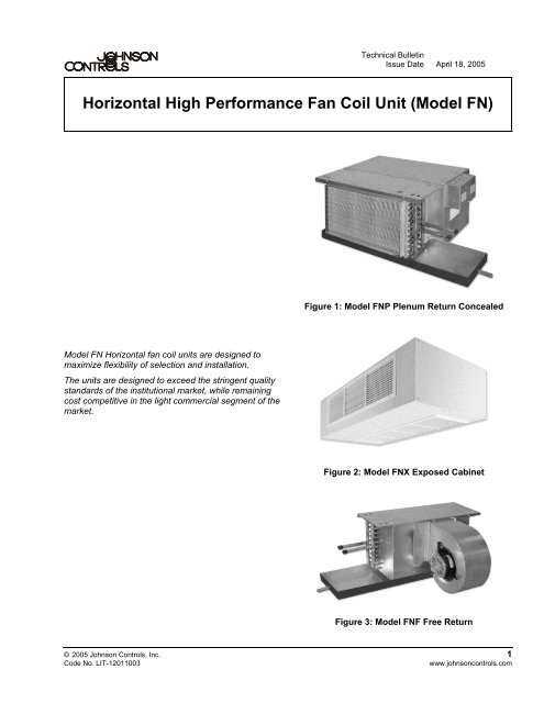
Figure 1: Model <strong>FNP</strong> Plenum Return Concealed<br />
Model FN Horizontal fan coil units are designed to<br />
maximize flexibility of selection and installation.<br />
The units are designed to exceed the stringent quality<br />
standards of the institutional market, while remaining<br />
cost competitive in the light commercial segment of the<br />
market.<br />
Figure 2: Model FNX Exposed Cabinet<br />
Figure 3: Model FNF Free Return<br />
© 2005 Johnson Controls, Inc. 1<br />
Code No. LIT-12011003<br />
www.johnsoncontrols.com
Unit Arrangements<br />
Figure 8: Model <strong>FNP</strong> Rear Return with Solid<br />
Access Panel<br />
Figure 4: Model <strong>FNP</strong> Bottom Return<br />
Figure 5: Model <strong>FNP</strong> Rear Return<br />
Figure 9: Model <strong>FNP</strong> Bottom Return with Bottom<br />
Ceiling Panel<br />
Figure 10: Model FNF Free Return<br />
Figure 6: Model <strong>FNP</strong> Bottom Return with<br />
Telescoping Bottom Panel<br />
Figure 11: Model FNM Mixing Box with Bottom and<br />
Rear Return<br />
Figure 7: Model FNM Mixing Box with Top and<br />
Rear Return<br />
2 Horizontal High Performance Fan Coil Unit (Model FN) <strong>Tech</strong>nical Bulletin
Figure 12: Model FNX Double Deflection Supply<br />
Grille and Ducted Rear Return<br />
Figure 15: Model FNX Ducted Supply and Single<br />
Deflection Rear Return Grille<br />
Figure 13: Model FNX Double Deflection Supply<br />
Grille and Single Deflection Bottom Return Grille<br />
Figure 16: Model FNX Ducted Supply and Ducted<br />
Rear Return<br />
Figure 14: Model FNX Double Deflection Supply<br />
Grille and Single Deflection Rear Return Grille<br />
Figure 17: Model FNX Ducted Supply and Single<br />
Deflection Bottom Return Grille<br />
Horizontal High Performance Fan Coil Unit (Model FN) <strong>Tech</strong>nical Bulletin 3
Physical Data<br />
Table 1: ARI Standard Ratings<br />
Model<br />
FNF<br />
<strong>FNP</strong><br />
Unit<br />
Size<br />
ARI 440<br />
Certified Rows FPI<br />
Coil Cooling Capacity Water<br />
Airflow CFM<br />
(Dry Flow)<br />
QT<br />
(BTUH)<br />
QS<br />
(BTUH)<br />
Flow Rate<br />
GPM<br />
WPD<br />
ft wg<br />
Power Input (Watts)<br />
06 • 4 10 700 17800 14000 3.7 1.6 290<br />
08 • 4 10 900 23500 18500 4.9 1.9 410<br />
10 • 4 10 1100 29400 22900 6.0 2.2 470<br />
12 • 4 10 1400 43000 31800 8.7 4.2 560<br />
14 4 10 1750 47100 36250 9.6 3.0 715<br />
16 4 10 2000 51000 41000 10.5 2.0 830<br />
18 4 10 2200 53000 42000 11.0 2.2 850<br />
20 4 10 2300 56000 44000 11.4 2.5 870<br />
Note: Based on 80°F Dry Bulb (DB) and 67°F Wet Bulb (WB) Entering Air Temperature (EAT), 45°F Entering Water<br />
Temperature (EWT), 10°F temperature rise, high fan speed. Motor type is Permanent Split Capacitor (PSC) and motor<br />
voltage is 115/1/60. Airflow under dry coil conditions. All models tested at 0.05” ESP.<br />
Airflow rate CFM on sizes 14 - 20 exceed maximum ratings in Air Conditioning and Refrigeration Institute (ARI) 440 and are<br />
therefore not certified.<br />
Table 2: Heating Capacity<br />
Model<br />
FNF<br />
<strong>FNP</strong><br />
Unit<br />
Size<br />
Nominal<br />
CFM<br />
QS<br />
(MBH)<br />
1 Row 2 Row 3 Row 4 Row<br />
GPM<br />
WPD<br />
QS<br />
(MBH)<br />
GPM<br />
WPD<br />
QS<br />
(MBH)<br />
GPM<br />
WPD<br />
QS<br />
(MBH)<br />
06 600 17.5 0.9 1.6 30.2 1.5 1.4 41.7 2.1 1.0 48.3 2.5 0.9<br />
08 800 24.3 1.2 3.2 41.8 2.1 2.6 57.6 2.9 2.0 66.5 3.4 1.6<br />
10 1000 27.8 1.4 0.8 52.4 2.7 4.1 70.5 3.6 1.5 80.6 4.1 1.0<br />
12 1200 34.5 1.8 0.9 61.8 3.2 1.8 86.4 4.4 2.3 98.8 5.1 1.6<br />
14 1400 41.3 2.1 1.7 73.4 3.8 2.6 98.6 5.0 1.4 117.1 6.0 1.8<br />
16 1600 48.1 2.5 2.4 85.1 4.4 3.6 114.5 5.9 1.9 126.5 6.5 0.6<br />
18 1800 54.9 2.8 3.2 96.8 5.0 4.9 130.4 6.7 2.5 144.7 7.4 0.7<br />
20 2000 61.0 3.1 4.1 107.5 5.5 6.1 145.3 7.4 2.4 161.7 8.3 0.9<br />
Note: Based on 70°F DB EAT, 180°F EWT, 40°F temperature drop, high fan speed.<br />
FNX performance data varies from <strong>FNP</strong> and FNF units. Contact the factory for more information.<br />
GPM<br />
WPD<br />
4 Horizontal High Performance Fan Coil Unit (Model FN) <strong>Tech</strong>nical Bulletin
Table 3: Unit Weight Data<br />
Total<br />
Coil<br />
Rows<br />
Unit Size<br />
Component<br />
06 08 10 12 14 16 18 20<br />
FNF Base Unit 68 (31) 73 (33) 77 (35) 114 (52) 119 (54) 124 (56) 128 (58) 132 (60)<br />
<strong>FNP</strong> Base Unit 87 (40) 95 (43) 101 (46) 141 (64) 150 (68) 157 (71) 164 (75) 170 (77)<br />
<strong>FNP</strong> with Mixing Box 119 (54) 132 (60) 144 (65) 189 (86) 204 (93) 217 (99) 229 (104) 246 (112)<br />
FNX Base Unit 137 (62) 146 (66) 158 (72) 202 (92) 219 (99) 228 (103) 240 (109) 250 (113)<br />
1 Row - Dry 5 (2) 6 (3) 7 (3) 8 (4) 10 (5) 10 (5) 11 (5) 12 (5)<br />
1 Row - Wet 7 (3) 9 (4) 10 (5) 11 (5) 14 (6) 14 (6) 16 (7) 17 (8)<br />
2 Row - Dry 11 (5) 13 (6) 14 (6) 16 (7) 20 (9) 20 (9) 22 (10) 24 (11)<br />
2 Row - Wet 14 (6) 18 (8) 20 (9) 23 (10) 27 (12) 28 (13) 32 (15) 35 (16)<br />
3 Row - Dry 16 (7) 19 (9) 21 (10) 24 (11) 30 (13) 30 (14) 33 (15) 36 (16)<br />
3 Row - Wet 21 (10) 27 (12) 30 (14) 34 (15) 41 (19) 42 (19) 48 (22) 52 (24)<br />
4 Row - Dry 21 (10) 25 (12) 29 (13) 33 (15) 40 (18) 40 (18) 44 (20) 48 (22)<br />
4 Row - Wet 27 (12) 35 (16) 41 (19) 46 (21) 54 (25) 56 (25) 64 (29) 69 (31)<br />
5 Row - Dry 26 (12) 30 (14) 34 (16) 38 (17) 42 (19) 46 (21) 50 (23) 54 (25)<br />
5 Row - Wet 33 (15) 39 (18) 45 (21) 51 (23) 57 (26) 63 (29) 70 (32) 77 (35)<br />
6 Row - Dry 32 (15) 38 (17) 43 (19) 49 (22) 59 (27) 61 (28) 67 (30) 71 (32)<br />
6 Row - Wet 42 (19) 53 (24) 61 (28) 69 (31) 80 (36) 85 (39) 97 (44) 103 (47)<br />
7 Row - Dry 38 (17) 42 (19) 48 (22) 54 (25) 60 (28) 66 (30) 72 (33) 78 (35)<br />
7 Row - Wet 49 (23) 56 (26) 63 (29) 70 (32) 77 (35) 84 (38) 91 (42) 98 (45)<br />
8 Row - Dry 43 (20) 49 (22) 55 (25) 61 (28) 67 (30) 73 (33) 79 (36) 85 (39)<br />
8 Row - Wet 55 (26) 63 (29) 71 (32) 79 (36) 87 (40) 95 (43) 103 (47) 111 (50)<br />
Note: Unit weight data is in pounds (kilograms).<br />
Horizontal High Performance Fan Coil Unit (Model FN) <strong>Tech</strong>nical Bulletin 5
PSC Fan Performance Curves<br />
Fan curves on the following pages depict actual<br />
performance of each motor tap without any additional<br />
fan balance adjustment. Actual capacities that fall<br />
below each curve can be obtained by adding an<br />
adjustment device. Do not run units prior to installation<br />
of downstream ductwork as damage to the motor may<br />
result.<br />
FN fan coil units are equipped with PSC motors with<br />
three separate windings (High, Medium, and Low) that<br />
provide variable horsepower outputs. Most often, size<br />
selections are conservative and actual CFM<br />
requirements and/or external static pressure<br />
requirements are lower than those specified. In this<br />
case, the unit fan motor can run at low or medium tap,<br />
substantially reducing the operating cost of the unit.<br />
All fan curves are for 115/1/60 motors and include<br />
pressure losses for a cabinet, electric heater, and 3- or<br />
4-row coil. Plenum units include a clean 1” throwaway<br />
filter. For other coil configurations, adjust performance<br />
curves based on pressure losses for the coils.<br />
For additional high static pressure applications and<br />
rating points, contact the factory.<br />
Figure 18: Model FNF Free Return Size 06<br />
Figure 19: Model FNF Free Return Size 08<br />
Figure 20: Model FNF Free Return Size 10<br />
6 Horizontal High Performance Fan Coil Unit (Model FN) <strong>Tech</strong>nical Bulletin
Figure 21: Model FNF Free Return Size 12<br />
Figure 24: Model FNF Free Return Size 18<br />
Figure 22: Model FNF Free Return Size 14<br />
Figure 25: Model FNF Free Return Size 20<br />
Figure 23: Model FNF Free Return Size 16<br />
Horizontal High Performance Fan Coil Unit (Model FN) <strong>Tech</strong>nical Bulletin 7
Figure 26: Model <strong>FNP</strong> Plenum Return Size 06<br />
Figure 29: Model <strong>FNP</strong> Plenum Return Size 12<br />
Figure 30: Model <strong>FNP</strong> Plenum Return Size 14<br />
Figure 27: Model <strong>FNP</strong> Plenum Return Size 08<br />
Figure 31: Model <strong>FNP</strong> Plenum Return Size 16<br />
Figure 28: Model <strong>FNP</strong> Plenum Return Size 10<br />
8 Horizontal High Performance Fan Coil Unit (Model FN) <strong>Tech</strong>nical Bulletin
Figure 32: Model <strong>FNP</strong> Plenum Return Size 18<br />
Figure 33: Model <strong>FNP</strong> Plenum Return Size 20<br />
Horizontal High Performance Fan Coil Unit (Model FN) <strong>Tech</strong>nical Bulletin 9
Figure 34: Model FNX Exposed Cabinet Size 06<br />
Figure 37: Model FNX Exposed Cabinet Size 12<br />
Figure 35: Model FNX Exposed Cabinet Size 08<br />
Figure 38: Model FNX Exposed Cabinet Size 14<br />
Figure 36: Model FNX Exposed Cabinet Size 10<br />
Figure 39: Model FNX Exposed Cabinet Size 16<br />
10 Horizontal High Performance Fan Coil Unit (Model FN) <strong>Tech</strong>nical Bulletin
Figure 40: Model FNX Exposed Cabinet Size 18<br />
Figure 41: Model FNX Exposed Cabinet Size 20<br />
Horizontal High Performance Fan Coil Unit (Model FN) <strong>Tech</strong>nical Bulletin 11
Electronically Commutated Motor (ECM)<br />
Fan Performance Curves<br />
The fan curves on the following pages depict actual<br />
performance at the maximum speed of the ECM<br />
motor. Depending upon external static pressure, flow<br />
rates are achievable anywhere within the curve<br />
boundary by adjusting the motor speed through the<br />
electronic interface control board.<br />
Once the electronic interface control board is set to the<br />
desired flow rate, airflow rates will be constant for<br />
varying degrees of external static pressure caused by<br />
filter loading or other duct system variables.<br />
Fan curves compensate for pressure losses of the unit<br />
cabinet, coil rows, filter loading, and other optional<br />
accessories.<br />
ECM motors operate using a rectified Alternating<br />
Current (AC) power source that is converted to a<br />
non-sinusoidal Direct Current (DC) power wave form.<br />
Harmonic distortion may occur and circulate on the<br />
power distribution system. Circulating harmonic<br />
currents are potentially additive on the neutral<br />
conductors of 3-phase, 4-wire Wye distribution<br />
systems. Neutral conductors must be engineered to<br />
account for the additional current (amperes)<br />
encountered.<br />
Figure 43: Model <strong>FNP</strong> Size 08 with 1/3 hp<br />
ECM Motor<br />
Figure 44: Model <strong>FNP</strong> Size 10 with 1/3 hp<br />
ECM Motor<br />
Figure 42: Model <strong>FNP</strong> Size 06 with 1/3 hp<br />
ECM Motor<br />
Figure 45: Model <strong>FNP</strong> Size 12 with (2) 1/3 hp<br />
ECM Motors<br />
12 Horizontal High Performance Fan Coil Unit (Model FN) <strong>Tech</strong>nical Bulletin
Table 4: ECM Airflow<br />
Unit<br />
Size<br />
Factory Set<br />
CFM Range<br />
CFM Min. Max.<br />
06 600 200 700<br />
08 800 300 900<br />
10 1000 300 1000<br />
12 1200 400 1500<br />
14 1400 600 1800<br />
16 1600 600 1900<br />
18 1800 600 2000<br />
20 2000 600 2000<br />
Figure 46: Model <strong>FNP</strong> Size 14 with (2) 1/3 hp<br />
ECM Motors<br />
Figure 47: Model <strong>FNP</strong> Size 16 with (2) 1/3 hp<br />
ECM Motors<br />
Figure 48: Model <strong>FNP</strong> Sizes 18/20 with (2) 1/3 hp<br />
ECM Motors<br />
Horizontal High Performance Fan Coil Unit (Model FN) <strong>Tech</strong>nical Bulletin 13
Motor, Fan, and Sound Data<br />
Table 5: Motor and Fan Data<br />
Unit<br />
Size<br />
06<br />
08<br />
10<br />
12<br />
14<br />
16<br />
18<br />
20<br />
Notes:<br />
Fan<br />
Speed<br />
Motor hp<br />
Amperes @ 120/1/60 Amperes @ 208-230/1/60 Amperes @ 277/1/60<br />
(Quantity)<br />
Fan<br />
ECM ECM ECM<br />
# PSC<br />
PSC<br />
PSC<br />
PSC<br />
ECM<br />
FLA<br />
3-Phase<br />
Neutral<br />
Current<br />
FLA<br />
3-Phase<br />
Neutral<br />
Current<br />
High (1) 1/6 2.6 1.1 0.9<br />
Medium (1) 1/8 (1) 1/3 1 2.1 5.0 13.2 0.9 2.8 5.9 0.8<br />
Low (1) 1/10<br />
1.8<br />
High (1) 1/4 3.8 1.6 1.3<br />
Medium (1) 1/6 (1) 1/3 1 3.3 5.0 13.2 1.0 2.8 5.9 0.8<br />
Low (1) 1/8<br />
2.6<br />
High (1) 1/4 4.9 2.2 1.9<br />
Medium (1) 1/5 (1) 1/3 1 4.1 5.0 13.2 1.5 2.8 5.9 1.2<br />
Low (1) 1/6<br />
3.2<br />
High (2) 1/6 5.2 2.2 1.8<br />
Medium (2) 1/8 (2) 1/3 2 4.2 10.0 26.4 1.8 5.6 11.8 1.6<br />
Low (2) 1/10<br />
3.6<br />
High (2) 1/4 7.6 3.2 2.6<br />
Medium (2) 1/6 (2) 1/3 2 6.6 10.0 26.4 2.0 5.6 11.8 1.6<br />
Low (2) 1/8<br />
5.2<br />
High (2) 1/4 9.8 4.4 3.8<br />
Medium (2) 1/5 (2) 1/3 2 8.2 10.0 26.4 3.0 5.6 11.8 2.4<br />
Low (2) 1/6<br />
6.4<br />
High (2) 1/4 9.8 4.4 3.8<br />
Medium (2) 1/5 (2) 1/3 2 8.2 10.0 26.4 3.0 5.6 11.8 2.4<br />
Low (2) 1/6<br />
6.4<br />
High (2) 1/4 9.8 4.4 3.8<br />
Medium (2) 1/5 (2) 1/3 2 8.2 10.0 26.4 3.0 5.6 11.8 2.4<br />
Low (2) 1/6<br />
Motor electrical data is nameplate data. Actual data will vary with application.<br />
Motors are nameplated for 208-230/1/60. Data is set at 230 volts.<br />
ECM motors operated on 208/1/60 power result in reduced airflow.<br />
6.4<br />
0.6<br />
0.8<br />
1.1<br />
1.2<br />
1.6<br />
2.2<br />
2.2<br />
2.2<br />
0.7<br />
0.7<br />
0.8<br />
1.4<br />
1.4<br />
1.6<br />
1.6<br />
1.6<br />
FLA<br />
3-Phase<br />
Neutral<br />
Current<br />
2.6 5.4<br />
2.6 5.4<br />
2.6 5.4<br />
5.2 10.8<br />
5.2 10.8<br />
5.2 10.8<br />
5.2 10.8<br />
5.2 10.8<br />
14 Horizontal High Performance Fan Coil Unit (Model FN) <strong>Tech</strong>nical Bulletin
Table 6: Sound Data<br />
Unit<br />
Size<br />
06<br />
08<br />
10<br />
12<br />
14<br />
16<br />
18<br />
20<br />
Notes:<br />
Fan<br />
Speed<br />
Unit<br />
SCFM<br />
Casing Radiated<br />
Octave Band Sound Power Levels, dB<br />
Free Inlet and Casing Radiated<br />
Octave Band Sound Power Levels, dB<br />
1 2 3 4 5 6 7 8 1 2 3 4 5 6 7 8<br />
High 610 70 68 63 58 57 52 46 42 72 71 63 60 60 57 52 47<br />
Medium 540 66 63 57 55 52 47 40 36 71 68 59 58 57 54 48 43<br />
Low 475 58 59 53 53 48 43 35 32 65 64 57 56 54 51 44 40<br />
High 790 66 64 62 59 58 53 47 42 68 68 63 61 61 58 53 47<br />
Medium 750 62 60 58 56 54 48 42 37 67 65 60 59 59 55 50 44<br />
Low 680 58 57 54 53 50 43 36 32 65 62 57 57 56 52 45 40<br />
High 915 67 65 63 60 59 54 47 44 69 69 64 62 62 59 53 49<br />
Medium 835 63 62 58 57 55 50 44 38 68 67 60 60 60 57 55 45<br />
Low 780 59 58 55 54 52 45 37 33 66 63 58 58 58 54 46 41<br />
High 1310 70 68 65 60 60 55 51 47 72 72 66 62 63 60 57 52<br />
Medium 1175 65 64 60 57 56 50 45 41 70 69 63 60 61 57 53 48<br />
Low 1050 63 61 56 55 50 45 39 35 70 66 59 58 57 53 49 43<br />
High 1650 69 67 68 63 62 57 52 48 71 71 68 65 65 62 58 53<br />
Medium 1400 65 64 64 61 59 53 48 44 70 69 66 64 64 60 56 51<br />
Low 1145 62 62 60 59 55 49 44 39 70 67 64 63 62 58 53 47<br />
High 1900 70 69 68 63 63 58 53 40 72 72 68 65 66 63 59 55<br />
Medium 1770 66 65 64 61 60 54 49 45 71 70 66 64 65 61 57 52<br />
Low 1610 63 62 60 59 56 50 45 41 71 67 64 63 62 59 54 48<br />
High 2000 70 67 67 63 63 59 54 50 72 71 68 65 66 64 60 55<br />
Medium 1850 66 64 65 61 60 55 51 46 71 69 67 64 65 62 59 53<br />
Low 1700 63 62 59 59 55 51 45 42 71 67 62 62 62 59 54 58<br />
High 2140 71 68 66 63 63 60 56 52 72 71 67 65 66 65 62 56<br />
Medium 1980 67 64 63 61 59 56 52 47 72 69 65 63 64 63 59 53<br />
Low 1800 64 61 58 58 55 52 46 41 71 66 61 61 61 60 55 48<br />
Sound data tested in accordance with ARI 260-01.<br />
Sound levels are expressed in decibels, dB RE: 1 x 10 -12 watts.<br />
Total sound power level data is based on Model <strong>FNP</strong> with fan CFM at corresponding fan speed with 115/1/60 volt motor,<br />
4-row coil, 1” throwaway filter, 0.25” external static pressure, and standard rated internal pressure losses.<br />
Horizontal High Performance Fan Coil Unit (Model FN) <strong>Tech</strong>nical Bulletin 15
Dimensional Data<br />
Drawings are not to scale and are not for installation purposes.<br />
Figure 49: Model FNF – Free Return Units<br />
16 Horizontal High Performance Fan Coil Unit (Model FN) <strong>Tech</strong>nical Bulletin
Figure 50: Model FNF – Free Return Units<br />
Horizontal High Performance Fan Coil Unit (Model FN) <strong>Tech</strong>nical Bulletin 17
Figure 51: Model <strong>FNP</strong> – Plenum Units<br />
18 Horizontal High Performance Fan Coil Unit (Model FN) <strong>Tech</strong>nical Bulletin
Figure 52: Model <strong>FNP</strong> – Plenum Units<br />
Horizontal High Performance Fan Coil Unit (Model FN) <strong>Tech</strong>nical Bulletin 19
Figure 53: Model FNM with Mixing Box<br />
20 Horizontal High Performance Fan Coil Unit (Model FN) <strong>Tech</strong>nical Bulletin
Figure 54: Model FNX – Exposed Cabinet Units<br />
Horizontal High Performance Fan Coil Unit (Model FN) <strong>Tech</strong>nical Bulletin 21
Figure 55: Model FN – Telescoping/Filter and Solid Bottom Access Panels<br />
22 Horizontal High Performance Fan Coil Unit (Model FN) <strong>Tech</strong>nical Bulletin
Controls Group<br />
507 E. Michigan Street<br />
P.O. Box 423<br />
Milwaukee, WI 53201<br />
Published in U.S.A.<br />
www.johnsoncontrols.com<br />
Horizontal High Performance Fan Coil Unit (Model FN) <strong>Tech</strong>nical Bulletin 23