for Wheel Loaders - HydraForce
for Wheel Loaders - HydraForce
for Wheel Loaders - HydraForce

Create successful ePaper yourself
Turn your PDF publications into a flip-book with our unique Google optimized e-Paper software.
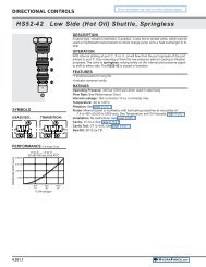
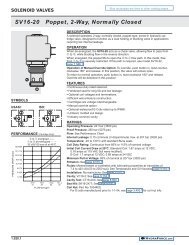
MAIN CONTROLS<br />
Bucket<br />
Brakes<br />
Steering<br />
Emergency Steering<br />
<strong>HydraForce</strong> offers valves that are well-suited<br />
to the unique needs of Dynamic Accumulator<br />
Charging Circuits which are commonly<br />
used in conjunction with steering and braking<br />
units. Hydraulic braking systems are common<br />
on wheel loaders and towable implements.<br />
These circuits require a delicate balance<br />
between the priority flow steering and braking<br />
sections of the application, while simultaneously<br />
allowing excess flow to be diverted to<br />
tank or various auxiliary functions.<br />
A typical circuit provides priority flow <strong>for</strong><br />
the steering orbital while maintaining a<br />
predetermined range of pressure in the<br />
accumulator(s), to ensure adequate supply of<br />
oil <strong>for</strong> up to 7 brake depressions in the case<br />
of power loss. If one accumulator fails, the<br />
LS10-41 will shift over to protect the operational<br />
one. The ECxx-42 provides priority flow<br />
in required amount while allowing excess flow<br />
to be used <strong>for</strong> auxiliary functions.<br />
Primary Functions<br />
Primary Functions are the basic / standard control circuits, such<br />
as Steering and Braking.<br />
Steering / Braking<br />
These functions have priority over all other hydraulic demands.<br />
<strong>HydraForce</strong> manufacture a range of priority on demand pressure<br />
compensators with dynamic load sensing <strong>for</strong> fast response. With<br />
7 different models of priority on demand pressure compensator<br />
valves (ECxx-43), the rated flow capacities range from 34 lpm to<br />
530 lpm (9 gpm to 140 gpm).<br />
Dual Accumulator Charging<br />
<strong>HydraForce</strong> inverted shuttle valve LS10-41 provides<br />
additional safety when using dual accumulators. In the event of<br />
one accumulator failing (i.e. a ruptured bladder, etc.), the failed<br />
accumulator is isolated from the rest of the circuit, allowing the<br />
second accumulator to supply steering / braking.<br />
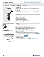
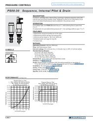
Primary Steering and Brake Solution<br />
BRAKES<br />
PRE-CHARGE<br />
BRAKES<br />
DYNAMIC<br />
STEERING<br />
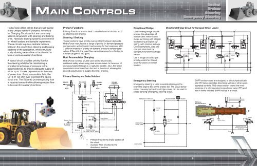
Directional Bridge<br />
Load-holding bridge circuits<br />
provide the advantage of<br />
independent meter-in and<br />
meter-out timing with integral<br />
load sensing and pilot signaling,<br />
with minimal leakage.<br />
Circuit complexity, size and<br />
cost are minimized by<br />
using multi-function cartridge<br />
valves.<br />
Use a bridge circuit to give<br />
priority control <strong>for</strong> lift and<br />
lower functions on wheel<br />
loaders.<br />
Emergency Steering<br />
Emergency steering is used to enable steering in the<br />
event the engine dies or the brakes fail. The circuit below<br />
shows one-way hydraulic cartridge valves can be used in<br />
a load-sensing emergency steering circuit.<br />
P<br />
LS<br />
T<br />
Directional Bridge Circuit <strong>for</strong> Compact <strong>Wheel</strong> Loader<br />
SPCL16-40<br />
EC16-32<br />
A B A<br />
B<br />
CV04-20<br />
SPCL16-40<br />
RV08-20<br />
SPCL10-30<br />
EC10-32<br />
LS04-B30<br />
RV08-20<br />
CV04-20<br />
SPCL10-30<br />
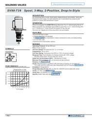
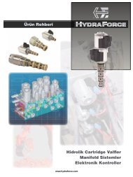
EHPR series valves are designed to electrohydraulically<br />
pilot PE Series cartridge directional valves or other spooloperated<br />
controls. This cross-section shows the inner<br />
workings of a pilot-operated proportional valve (PE) and<br />
how it works with the EHPR valves in a circuit.<br />
P<br />
LS<br />
T<br />
LS10-41<br />
EMERGENCY STEER OUT<br />
PRIMARY STEER<br />
SENSOR<br />
CV08-20<br />
PE Series<br />
Directional Valve<br />
6<br />
5 4 3 2<br />
CV12-20<br />
Steering Flow<br />
CV1<br />
1<br />
Excess Flow<br />
to Auxiliary<br />
Functions<br />
EC16-42<br />
UP10-40<br />
RV08-20 Valve<br />
(Set higher than UP Valve)<br />
Load Sense<br />
EMERGENCY<br />
STEER PUMP<br />
RV10-20<br />
PD12-44<br />
PD1<br />
TANK<br />
EHPR<br />
System Drain<br />
Pump<br />
Separate Drain Line<br />
prevents back pressure<br />
on PE valve<br />
EHPR<br />
• Primary Flow to the brake section of<br />
the circuit<br />
• Auxiliary Flow diverted to the<br />
directional function<br />
LOAD SENSE<br />
8 9