Classic Solar EnerSol, EnerSol T, OPzS Solar Operating ... - Ieeco.net
Classic Solar EnerSol, EnerSol T, OPzS Solar Operating ... - Ieeco.net
Classic Solar EnerSol, EnerSol T, OPzS Solar Operating ... - Ieeco.net

Create successful ePaper yourself
Turn your PDF publications into a flip-book with our unique Google optimized e-Paper software.
81700705<br />
<strong>Classic</strong> <strong>Solar</strong> <strong>EnerSol</strong>, <strong>EnerSol</strong> T, <strong>OPzS</strong> <strong>Solar</strong><br />
<strong>Operating</strong> Instructions<br />
for stationary lead acid batteries<br />
Nominal data<br />
• Nominal voltage U N<br />
• Nominal capacity C N = C 100 or C 120<br />
• Nominal discharge current I N = I 100 or I 120<br />
• Final discharge voltage U f<br />
• Nominal temperature T N<br />
: 2.0 V x number of cells<br />
: 120 h discharge (see type plate and technical data in these instructions)<br />
: I 100 = C 100 / 100 h or I 120 = C 120 120 h<br />
: see technical data in these instructions<br />
: 25° C<br />
Battery type:<br />
Number of cells/blocks:<br />
Assembly by: Exide Technologies order no.: date:<br />
Commissioned by:<br />
date:<br />
Security signs attached by:<br />
date:<br />
• Observe these Instructions and keep them located near the battery for future<br />
reference!<br />
• Work on the battery should only be carried out by qualified personnel.<br />
•<br />
•<br />
•<br />
•<br />
• Any acid splashes on the skin or in the eyes must be rinsed with plenty of<br />
clean water immediately. Then seek medical assistance.<br />
Spillages on clothing should be rinsed out with water!<br />
•<br />
•<br />
• Electolyte is strongly corrosive!<br />
•<br />
•<br />
•<br />
•<br />
•<br />
Do not smoke!<br />
Do not use any naked flame or other sources of ignition.<br />
Risk of explosion and fire!<br />
While working on batteries wear protective goggles and clothing!<br />
Observe the accident prevention rules as well as EN 50272-2,<br />
EN 50110-1!<br />
Explosion and fire hazard, avoid short circuits.<br />
Avoid electrostatic charges and discharges/sparks!<br />
Blocks/cells are very heavy! Make sure they are installed securely! Only use<br />
suitable means of transport!<br />
Block/cell containers are sensitive to mechanical damage.<br />
Handle with care!<br />
Caution! Dangerous voltage.<br />
Metal parts of the battery are always alive, therefore do not place<br />
items or tools on the battery!<br />
Non-compliance with operating instructions and installations or repairs made with other than<br />
original accessories and spare parts or with accessories and spare parts not recommended<br />
by the battery manufacturer or repairs made without authorization and use of additives for<br />
the electrolytes (alleged enhancing agents) render the warranty void.<br />
Pb<br />
Spent batteries have to be collected and recycled separately from normal household<br />
wastes (EWC 160601). The handling of spent batteries is described in the EU Battery<br />
Directive (2006/66/EC) and their national transitions (UK: HS Regulation 1994 No. 232,<br />
Ireland: Statory Instrument No. 73/2000). Contact your supplier to agree upon the<br />
recollection and recycling of your spent batteries or contact a local and authorized<br />
Waste Management Company.<br />
1. Start Up<br />
Check all cells/blocks for mechanical damage,<br />
correct polarity and firmly seated connectors.<br />
The following torques apply to the cell types:<br />
Ener Sol <strong>EnerSol</strong> T <strong>OPzS</strong> <strong>Solar</strong><br />
A-Pol (M 10) (M 8)<br />
8 Nm ± 1 25 Nm ±1 20 Nm ± 1<br />
Put on the terminal covers if necessary. Check<br />
the electrolyte level in all cells and if necessary<br />
top up to maximum level with purified water acc.<br />
to DIN 43530 Part 4. Connect the battery with<br />
the correct polarity to the charger (pos. pole to<br />
pos. terminal). The charger must not be switched<br />
on during this process, and the load must not be<br />
connected. Switch on charger and start charging<br />
following acc. to 2.2.<br />
If there is only an alternative source of energy<br />
available, then the battery must be charged until<br />
the cell voltage is the same in all cells and the<br />
electrolyte density has reached the nominal<br />
value (see technical data). The loads must be<br />
switched off during charging. The insulation resistance<br />
measured at the disconnected loads and<br />
charger should be ≥ 100 Ω per volt nominal voltage.<br />
2. Operation<br />
For the installation and operation of stationary<br />
batteries EN 50 272-2 is mandatory.<br />
The battery should always be operated using a<br />
charge controller and deep discharge protection.<br />
The battery must be installed so that it is not in<br />
direct sunlight and in a way which prevents<br />
ambiance-dependent temperature differences of<br />
> 3 K arising. The spacing between the cells or<br />
blocs should be 10 mm and at least 5 mm in rack<br />
mounting.<br />
2.1 Discharge<br />
Discharge must not be continued below the voltage<br />
recommended for the discharge time.<br />
Deeper discharges must not be carried out.<br />
Discharge should not exceed the nominal capacity.<br />
Unless otherwise indicated by the manufacturer.<br />
Recharge immediately following complete or<br />
partial discharge. A battery is regarded as discharged<br />
when the electrolyte density is < 1.13<br />
kg/l at 25° C. This corresponds to a discharge<br />
level of ca. 80% of the nominal value. An electrolyte<br />
density of < 1.13 kg/l is a deep discharge.<br />
Deep discharge reduces the lifetime of the battery.<br />
2.2 Charging<br />
a) using an external charger<br />
All charging characteristics with their specific<br />
data, described in<br />
DIN 41773 (IU-characteristic; I-const.: ± 2%;<br />
U-const.: ± 1%)<br />
DIN 41774 (W-characteristic; ± 0.05 Vpc)<br />
DIN 41776 (I-characteristic; I-const.: ± 2%)<br />
may be used. Depending on to the charging<br />
equipment, specification and characteristics,<br />
alternating currents flow through the battery<br />
superimposing onto the direct current during<br />
charge operation.<br />
Alternating currents and the reaction from the<br />
loads may lead to an additional temperature<br />
increase of the battery, and strain the electrodes<br />
causing possible damage (see point 2.5), which<br />
can shorten the battery life.<br />
When charging with an external charger, the battery<br />
is disconnected from the load. The temperature<br />
must be monitored. Towards the end of<br />
the charging process the charge voltage of the<br />
battery is 2.6 V - 2.75 V times the number of<br />
cells. The charging process must be monitored<br />
(see points 2.4, 2.5 and 2.6)! On reaching a fully<br />
charged state, the charging process must be<br />
stopped or switched to the float charge voltage<br />
as in table 1. For charge current see point 2.6.<br />
b) with alternative power supply<br />
When using power supply units with solar modules<br />
or wind generators, the battery charger is not<br />
able to supply the maximum load current at all<br />
times. The load current intermittently exceeds<br />
the nominal current of the battery charger.<br />
During this period the battery supplies power.<br />
This results in the battery not being fully charged<br />
at all times. Therefore, depending on the load the<br />
charge voltage must be set at 2.23 V - 2.35 V x<br />
number of cells. This has to be carried out in
accordance with the manufacturers instructions.<br />
Recommended charge voltage for cyclical application:<br />
Depending on the depth of discharge and the<br />
load the charge voltage is adjusted according to<br />
the specified values on table 1.<br />
Range<br />
Charge voltage [Vpc]<br />
<strong>EnerSol</strong> 2.32 - 2.40<br />
<strong>EnerSol</strong> T 2.30 - 2.40<br />
<strong>OPzS</strong> <strong>Solar</strong> 2.28 - 2.40<br />
Table 1: Recommended charge voltage for cyclical<br />
application<br />
The charge voltage has to be adjusted to reach<br />
the nominal value ± 0.01 kg/l (see technical data)<br />
once a month. If this is not the case, it is necessary<br />
to increase the recommended charge voltage<br />
stepwise by approximately 20 mVpc to a maximum<br />
of 2.40 Vpc according to table 1 or carry<br />
out an equalizing charge acc. to 2.4 every month.<br />
2.3 Maintaining full charge<br />
(float charging)<br />
The devices used must comply with the stipulations<br />
under DIN 41773. They are to be set so that<br />
the average cell voltage is as in table 2 and the<br />
electrolyte density should not decrease over a<br />
lengthy period, if necessary the charge voltage<br />
Range<br />
Float charge voltage [Vpc]<br />
<strong>EnerSol</strong> 2.27<br />
<strong>EnerSol</strong> T 2.25<br />
<strong>OPzS</strong> <strong>Solar</strong> 2.23<br />
Table 2: Float charge voltage<br />
must be increased acc. to table 1.<br />
2.4 Equalizing charge<br />
Because it is possible to exceed the permitted<br />
load voltages, appropriate measures must be<br />
taken, e.g. switch off the load.<br />
Equalizing charges are required after deep discharges<br />
and/or inadequate charges.<br />
They can be carried out as follows:<br />
a) Using alternative form of power supply<br />
– at constant voltage of max. 2.4 Vpc up to<br />
72 hours (the number of hours increases<br />
with less charging current acc.to table 3).<br />
b) Using an external charger<br />
– at constant voltage of max. 2.4 Vpc up to<br />
72 hours<br />
– with I- or W-characteristic as in point 2.6.<br />
The electrolyte temperature must never exceed<br />
55° C. If it does, stop charging or revert to float<br />
charge to allow the temperature to drop.<br />
The end of the equalizing charge is reached<br />
when the electrolyte density and the cell voltages<br />
no longer increase over a period of 2 hours<br />
(2 h-criterion only applies to I- and W-characteristics).<br />
2.5 Alternating currents<br />
When recharging or boost charging up to 2.4<br />
Vpc under operation modes 2.2 the value of the<br />
alternating current is occasionally permitted to<br />
reach 10 A per 100 Ah C 10 .<br />
In a fully charged state during float charge or<br />
standby parallel operation the value of the alternating<br />
current must not exceed 5 A per 100 Ah<br />
C 10 .<br />
2.6 Charging currents<br />
When charging with the IU-characteristic, the<br />
charging current should be 10 A to 35 A / 100 Ah<br />
C 10 (reference values).<br />
Exceeding this voltage of 2.4 Vpc increases<br />
water decomposition. Charging in cyclical application<br />
generates more heat. For that reason the<br />
charging currents shown in the following table 3<br />
must not be exceeded.<br />
Charging Max. charging Charging<br />
procedure current voltage<br />
[A/100 Ah C 10 ] [Vpc]<br />
IU-characteristic 35 2.40<br />
I-characteristic 5 2.60 - 2.75<br />
W-characteristic<br />
7 at 2.40<br />
3.5 at 2.65<br />
Table 3: Maximal charging currents with different<br />
characteristics<br />
2.7 Temperature<br />
The recommended operating temperature range<br />
for lead acid batteries is 10° C to 30° C. All technical<br />
data apply to the nominal temperature 25° C.<br />
The ideal operating temperature is 25° C ± 5 K.<br />
(<strong>OPzS</strong> <strong>Solar</strong> =20° C)<br />
Higher temperatures will seriously reduce service<br />
life. Lower temperatures reduce the available<br />
capacity. The absolute maximum temperature is<br />
55° C.<br />
2.8 Temperature-related charge voltage<br />
A temperature related adjustment of the charge<br />
voltage within the operating temperature of 10° C<br />
to 30° C is not necessary. If the operating temperature<br />
is constantly outside this range, the<br />
charge voltage has to be adjusted.<br />
The temperature correction factor is -0.004 Vpc<br />
per K. If the temperature is constantly in excess<br />
of 40° C, the factor is -0.003 Vpc per K.<br />
2.9 Electrolyte<br />
The electrolyte is diluted sulphuric acid. The<br />
nominal electrolyte density ± 0.01 kg/l (acc. to<br />
technical data) is based on 25° C when fully<br />
charged and with the maximum electrolyte level.<br />
Higher temperatures reduce electrolyte density,<br />
lower temperatures increase electrolyte density.<br />
The appropriate correction factor is - 0.0007 kg/l<br />
per K.<br />
Example: electrolyte density of 1.23 kg/l at 40° C<br />
corresponds to a density of 1.24 kg/l at 25° C or<br />
an electrolyte density of 1.25 kg/l at 10° C corresponds<br />
to a density of 1.24 kg/l at 25° C.<br />
3. Battery maintenance and control<br />
The electrolyte level must be checked regularly.<br />
If it drops to the lower electrolyte level mark,<br />
purified water must be added in accordance with<br />
DIN 43530 Part 4 (maximum conductivity 30<br />
µS/cm). Keep the battery clean and dry to avoid<br />
leakage currents. Plastic parts of the battery,<br />
especially containers, must be cleaned with<br />
clean water without additives.<br />
Monthly measurements and recording:<br />
• Battery voltage<br />
• Voltage of some cells/block batteries<br />
• Electrolyte temperature of some cells<br />
• Battery-room temperature<br />
• Electrolyte density of some cells<br />
It is necessary to carry out an equalizing charge<br />
acc. to 2.4 if the cell/block average float charge<br />
voltages (see table 2) differ more than those in<br />
table 4 below and/or if the electrolyte density of<br />
the cells of a battery string deviates from the<br />
average-value more than ± 0.01 kg/l.<br />
Tolerance 2 V-Cell 6 V-Block 12 V-Block<br />
+ 0.10 V 0.17 V 0.24 V<br />
– 0.05 V 0.09 V 0.12 V<br />
Table 4<br />
Annual measurements and recording:<br />
• Voltage of all cells/block batteries<br />
• Electrolyte temperature of all cells<br />
• Electrolyte density of all cells<br />
Annual visual check:<br />
• Screw connections<br />
• Screw connections without locking devices<br />
have to be checked for tightness<br />
• Battery installation and arrangement<br />
• Ventilation the battery room<br />
4. Tests<br />
Tests have to be carried out according to<br />
IEC 60896-11 and DIN 43539 Part1. Special<br />
instructions like VDE 0107 and EN 50172 have<br />
to be observed.<br />
5. Faults<br />
Call the service agents immediately if faults in<br />
the battery or charging unit are found. Recorded<br />
data as described in point 3 simplify the troubleshooting<br />
and fault clearance. A service contract<br />
for example with Exide Technologies facilitates<br />
detecting faults in time.<br />
6. Storage and taking out of operation<br />
To store or decommission cells/blocs for a longer<br />
period of time, they should be fully charged<br />
and stored in a dry and cold but frost-free room,<br />
away from direct sunlight. To avoid damage, the<br />
following charging methods can be chosen:<br />
1. Equalizing charges every three months as<br />
described under point 2.4.<br />
At average ambient temperatures of more<br />
than the nominal temperature shorter intervals<br />
can be necessary.<br />
2. Float charging as under point 2.3.<br />
7. Transport<br />
To prevent any leakage of electrolyte, the cells/<br />
block batteries must be transported in an upright<br />
position. Cells/block batteries without any visible<br />
damage are not defined as hazardous goods<br />
under the regulations for transport of hazardous<br />
goods by road (ADR) or by rail (RID). They must<br />
be protected against short circuits, slipping,<br />
upsetting or damaging. Bloc batteries may be<br />
suitably stacked and secured on pallets (ADR<br />
and RID, special provision 598). It is prohibited<br />
to stack pallets. No dangerous traces of acid<br />
may be found on the exteriors of the packing<br />
units. Cells/bloc batteries whose cases leak or<br />
are damaged must be packed and transported<br />
as class 8 hazardous goods under UN no. 2794.<br />
8. Technical data<br />
The nominal voltage, the number of cells, the<br />
nominal capacity (C 100 or C 120 = C N ) and the battery<br />
type are described on the type plates. See<br />
table 8.1.1 - 8.1.3 other capacities at different<br />
discharge currents with the corresponding<br />
discharge times.
8.1 Measurements, weights and capacities (C n ) at different discharge times (t n ) and final discharge voltage (U f )<br />
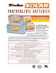
8.1.1 Stationary lead acid bloc batteries type <strong>EnerSol</strong><br />
with positive and negative grid plates, Nominal electrolyte density 1.28 kg/l<br />
Discharge data<br />
Measurements and weights<br />
Capacity [Ah] Discharge current [A] Length Width Height 1) Weight Weight<br />
Discharge time<br />
max. max. max. including acid<br />
120 100 120 100<br />
[h]<br />
acid<br />
Final discharge<br />
approx. approx<br />
1.85 1.85 1.85 1.85<br />
voltage [Vpc] [mm] [mm] [mm] [kg] [kg]<br />
<strong>EnerSol</strong> 50 53 52 0.44 0.52 210 175 190 13.7 2.1<br />
<strong>EnerSol</strong> 65 66 65 0.55 0.65 242 175 190 17.3 2.7<br />
<strong>EnerSol</strong> 80 80 78 0.67 0.78 278 175 190 20.7 4.7<br />
<strong>EnerSol</strong> 100 99 97 0.83 0.97 353 175 190 26.4 7.0<br />
<strong>EnerSol</strong> 130 132 130 1.10 1.30 349 175 290 33.0 10.9<br />
<strong>EnerSol</strong> 175 179 175 1.49 1.75 513 223 223 47.8 14.6<br />
<strong>EnerSol</strong> 250 256 250 2.13 2.50 518 276 242 63.0 18.6<br />
1)<br />
The above mentioned height can differ depending on the used vents<br />
8.1.2 Stationary lead acid cells type <strong>EnerSol</strong> T<br />
with positive and negative grid plates, Nominal electrolyte density 1.26 kg/l<br />
Discharge data<br />
Measurements and Weights<br />
Capacity [Ah] Discharge current [A] Length Width Height 1) Weight Weight<br />
Discharge time<br />
max. max. max. including acid<br />
120 48 24 10 120 48 24 10<br />
[h]<br />
acid<br />
Final discharge<br />
approx. approx.<br />
1.85 1.80 1.80 1.80 1.85 1.80 1.80 1.80<br />
voltage [V] [mm] [mm] [mm] [kg] [kg]<br />
<strong>EnerSol</strong> T 370 367 361 333 280 3.06 7.52 13.88 28.0 83 198.5 445 17.3 5.1<br />
<strong>EnerSol</strong> T 460 452 437 416 350 3.77 9.10 17.33 35.0 101 198.5 445 21.0 6.3<br />
<strong>EnerSol</strong> T 550 542 524 499 425 4.52 10.92 20.79 42.5 119 198.5 445 24.7 7.5<br />
<strong>EnerSol</strong> T 650 668 656 625 527 5.57 13.67 26.04 52.7 119 198.5 508 29.5 8.6<br />
<strong>EnerSol</strong> T 760 779 766 729 615 6.49 15.96 30.38 61.5 137 198.5 508 31.0 10.0<br />
<strong>EnerSol</strong> T 880 897 854 840 714 7.48 17.79 35.00 71.4 137 198.5 556 38.0 11.0<br />
<strong>EnerSol</strong> T 1000 1025 1008 960 809 8.54 21.00 40.00 80.9 155 198.5 556 43.1 12.6<br />
<strong>EnerSol</strong> T 1130 1154 1134 1080 910 9.62 23.63 45.00 91.0 173 198.5 556 47.7 14.1<br />
<strong>EnerSol</strong> T 1250 1282 1260 1200 1011 10.68 26.25 50.00 101.1 191 198.5 556 52.8 15.6<br />
1)<br />
The above mentioned height can differ depending on the used vents
8.1.3 Stationary lead acid bloc batteries type <strong>OPzS</strong> <strong>Solar</strong> bloc batteries and single cells<br />
with positive tubular plates and negative grid plates, Nominal electrolyte density 1.24 kg/l<br />
Bloc battery<br />
Discharge data<br />
Measurements and Weights<br />
Capacity [Ah] Discharge current [A] Length Width Height 1) Weight Weight<br />
Discharge time<br />
max. max. max. including acid<br />
120 48 24 10 120 48 24 10<br />
[h]<br />
acid<br />
Final discharge<br />
approx. approx.<br />
1.85 1.80 1.80 1.80 1.85 1.80 1.80 1.80<br />
voltage [V] [mm] [mm] [mm] [kg] [kg]<br />
12V <strong>OPzS</strong> <strong>Solar</strong> 70 82.7 78.4 69.4 51.5 0.7 1.6 2.9 5.2 275 208 385 35 15<br />
12V <strong>OPzS</strong> <strong>Solar</strong> 140 139.0 141.0 118.0 103.0 1.2 2.9 4.9 10.3 275 208 385 45 14<br />
12V <strong>OPzS</strong> <strong>Solar</strong> 210 210.0 200.0 177.0 154.0 1.8 4.2 7.0 15.5 383 208 385 64 19<br />
6V <strong>OPzS</strong> <strong>Solar</strong> 280 294.0 296.0 250.0 206.0 2.5 6.2 10.5 20.6 275 208 385 41 13<br />
6V <strong>OPzS</strong> <strong>Solar</strong> 350 364.0 374.0 311.0 257.0 3.0 7.8 13.0 25.8 383 208 385 56 20<br />
6V <strong>OPzS</strong> <strong>Solar</strong> 420 417.0 420.0 354.0 309.0 3.5 8.8 14.8 30.9 383 208 385 63 20<br />
Single cell<br />
<strong>OPzS</strong> <strong>Solar</strong> 190 190 165 145.0 132.0 1.6 3.4 6.0 13.2 105 208 405 13.7 5.2<br />
<strong>OPzS</strong> <strong>Solar</strong> 245 245 215 190.0 173.0 2.0 4.5 7.9 17.3 105 208 405 15.2 5.0<br />
<strong>OPzS</strong> <strong>Solar</strong> 305 305 270 240.0 220.0 2.5 5.6 10.0 22.0 105 208 405 16.6 4.6<br />
<strong>OPzS</strong> <strong>Solar</strong> 380 380 330 300.0 273.0 3.2 6.9 12.5 27.3 126 208 405 20.0 5.8<br />
<strong>OPzS</strong> <strong>Solar</strong> 450 450 395 355.0 325.0 3.8 8.2 14.8 32.5 147 208 405 23.3 6.9<br />
<strong>OPzS</strong> <strong>Solar</strong> 550 550 480 430.0 391 4.6 10.0 17.9 39.1 126 208 520 26.7 8.1<br />
<strong>OPzS</strong> <strong>Solar</strong> 660 660 575 515.0 469 5.5 12.0 21.5 46.9 147 208 520 31.0 9.3<br />
<strong>OPzS</strong> <strong>Solar</strong> 765 765 670 600.0 546 6.4 14.0 25.0 54.6 168 208 520 35.4 10.8<br />
<strong>OPzS</strong> <strong>Solar</strong> 985 985 860 770 700 8.2 17.9 32.1 70.0 147 208 695 43.9 13.0<br />
<strong>OPzS</strong> <strong>Solar</strong> 1080 1080 940 845 773 9.0 19.6 35.2 77.3 147 208 695 47.2 12.8<br />
<strong>OPzS</strong> <strong>Solar</strong> 1320 1320 1150 1030 937 11.0 24.0 42.9 93.7 215 193 695 59.9 17.1<br />
<strong>OPzS</strong> <strong>Solar</strong> 1410 1410 1225 1105 1009 11.8 25.5 46.0 100.9 215 193 695 63.4 16.8<br />
<strong>OPzS</strong> <strong>Solar</strong> 1650 1650 1440 1290 1174 13.8 30.0 53.8 117.4 215 235 695 73.2 21.7<br />
<strong>OPzS</strong> <strong>Solar</strong> 1990 1990 1730 1550 1411 16.6 36.0 64.6 141.1 215 277 695 86.4 26.1<br />
<strong>OPzS</strong> <strong>Solar</strong> 2350 2350 2090 1910 1751 19.6 43.5 79.6 175.1 215 277 845 108.0 33.7<br />
<strong>OPzS</strong> <strong>Solar</strong> 2500 2500 2215 2015 1854 20.8 46.1 84.0 185.4 215 277 845 114.0 32.7<br />
<strong>OPzS</strong> <strong>Solar</strong> 3100 3100 2755 2520 2318 25.8 57.4 105.0 231.8 215 400 815 151.0 50.0<br />
<strong>OPzS</strong> <strong>Solar</strong> 3350 3350 2985 2740 2524 27.9 62.2 114.2 252.4 215 400 815 158.0 48.0<br />
<strong>OPzS</strong> <strong>Solar</strong> 3850 3850 3430 3135 2884 32.1 71.5 130.6 288.4 215 490 815 184.0 60.0<br />
<strong>OPzS</strong> <strong>Solar</strong> 4100 4100 3650 3355 3090 34.2 76.0 139.8 309.0 215 490 815 191.0 58.0<br />
<strong>OPzS</strong> <strong>Solar</strong> 4600 4600 4100 3765 3451 38.3 85.4 156.9 345.1 215 580 815 217.0 71.0<br />
1)<br />
The above mentioned height can differ depending on the used vents<br />
NXCSLOEPDF00710 · Druckhaus Bechstein · Printed in Germany · Subject to change without prior notice<br />
81700705 0,5 III.09<br />
Exide Technologies GmbH<br />
Im Thiergarten<br />
63654 Büdingen – Germany<br />
Tel.: +49 (0) 60 42 / 81 544<br />
Fax: +49 (0) 60 42 / 81 398<br />
www.industrialenergy.exide.com