PipeWIZARD Version 3 â
PipeWIZARD Version 3 â
PipeWIZARD Version 3 â

You also want an ePaper? Increase the reach of your titles
YUMPU automatically turns print PDFs into web optimized ePapers that Google loves.
A NEW, IMPROVED PIPELINE AUT GIRTH WELD INSPECTION<br />
SYSTEM<br />
Sebastien RIGAULT and Michael MOLES<br />
Olympus NDT, Quebec City, Canada<br />
ABSTRACT<br />
Automated ultrasonics is steadily becoming the standard method of inspection of pipeline<br />
girth welds throughout the world, particularly using phased arrays. Phased array AUT<br />
systems were first developed a decade ago, and proved to be much more flexible and<br />
capable than multiprobe systems, particularly for offshore special applications. A new<br />
version has been developed, which incorporates all the techniques developed previously,<br />
e.g. seamless pipe, thick section inspections, small diameter pipe inspections, clad pipe,<br />
and is significantly more powerful and flexible. A number of technical improvements<br />
have been made to software, instrumentation, computers, umbilical and probe pan.<br />
Overall, the new system has all the old system capabilities, plus significantly increased<br />
applications capability. Lastly, the new system requires no additional training and<br />
qualification. Some results with the new system will be shown.<br />
INTRODUCTION<br />
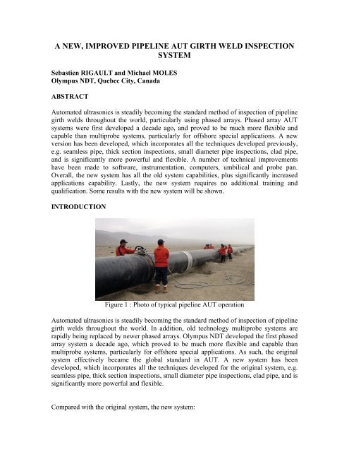
Figure 1 : Photo of typical pipeline AUT operation<br />
Automated ultrasonics is steadily becoming the standard method of inspection of pipeline<br />
girth welds throughout the world. In addition, old technology multiprobe systems are<br />
rapidly being replaced by newer phased arrays. Olympus NDT developed the first phased<br />
array system a decade ago, which proved to be much more flexible and capable than<br />
multiprobe systems, particularly for offshore special applications. As such, the original<br />
system effectively became the global standard in AUT. A new system has been<br />
developed, which incorporates all the techniques developed for the original system, e.g.<br />
seamless pipe, thick section inspections, small diameter pipe inspections, clad pipe, and is<br />
significantly more powerful and flexible.<br />
Compared with the original system, the new system:
• Has much improved ultrasonic performance<br />
• Is more robust<br />
• Is easier to upgrade<br />
• Is more maintainable<br />
• Is highly modular, i.e. flexible<br />
• Has increased applications capability<br />
• Requires no additional training and qualification.<br />
The new system can be configured to match the application, e.g. from thin onshore gas<br />
pipelines to thick risers and tendons, by changing the instrumentation and packaging. The<br />
instrumentation can be removed and placed near the weld if convenient. The umbilical is<br />
improved with lengths from 5m to 25m. The scanner is lighter and lower profile, with<br />
waterproof TOFD pre-amp. The instrumentation is upgraded to the Focus LT, including<br />
multiple units up to 128/256, while the software is based on TomoView 2.8 and is<br />
upgradeable. A much higher data transfer speed allows additional inspection techniques<br />
to be used simultaneously. For example A-scan compression is available for full data<br />
collection on S-scans. The ability to display strip charts, S-scans and merged views on the<br />
same display layout is good for detailed defect analysis. The computer is switched to a<br />
server for improved robustness. GPS is used for location, with wireless data transfer.<br />
Overall, the new system has all the original system capabilities, plus significantly<br />
increased applications capability. In addition, the new system has been designed so that<br />
no additional training is required for experienced operators, and no additional system<br />
approvals should be required outside regular project qualifications.<br />
BACKGROUND<br />
Historically, pipeline automated ultrasonic testing (AUT) was developed in Alberta by<br />
NOVA Corp and TransCanada Pipelines Ltd. from the 1960’s on (1). The technique used<br />
linear scanning for speed, strip charts for rapid data analysis, zone discrimination (i.e.<br />
tailored weld inspections), and customized calibration blocks. The technique developed<br />
to such an extent that two codes were written: ASTM E-1961 primarily for onshore use<br />
(2), and DNV OS F101 for offshore (3).<br />
At that time, the only ultrasonic technology available was multiprobes, which required<br />
large, heavy probe pans, which were inflexible. At the end of the 1990’s, R/ D Tech (now<br />
Olympus NDT) developed a phased array system equivalent to the multiprobe systems<br />
(4). Physically, the phased array systems had much smaller probe pans, were lighter, and<br />
significantly more flexible. The arrays had an automated Focal Law set-up (called the<br />
“Garden Gate”), which was a major convenience. Phased arrays could perform additional<br />
scans, which allowed many different inspection options. For example, the original phased<br />
array system could generate 128 channels in four views, which was a major improvement<br />
over multiprobe systems’ 24 channels. Subsequently, other manufacturers have<br />
developed phased array pipeline AUT systems, though the original system remains the<br />
market leader.
Additional applications typically came from offshore requests, e.g. seamless pipe, high<br />
quality thick pipe, small diameter pipe, and clad pipe (5). The seamless pipe was<br />
addressed by running multiple set-ups simultaneously (6), the premium thick pipe by<br />
using additional beams, and the small diameter pipe by using an additional scanner. Clad<br />
pipe is similar to the nuclear austenitic pipe inspections – also best performed by phased<br />
arrays, and uses a different approach with multiple S-scans. The original phased array<br />
AUT system has been used to address all these procedures. However, in some<br />
applications, an improved or more powerful system would have helped; as a result, a<br />
completely re-designed phased array AUT system has been developed to address these<br />
applications, and to take advantage of new technology.<br />
NEW SYSTEM OVERVIEW<br />
Changes have been made in the following areas:<br />
• Hardware<br />
• Software<br />
• Mechanics<br />
• Umbilicals<br />
This will lead to:<br />
• Improved performance<br />
• More robust system<br />
• Easier to upgrade<br />
• More maintainable<br />
• Highly modular<br />
• Increased applications capability<br />
• Similar price (depending on configuration).<br />
Overal l, this will lead to a more configurable system, improved mechanics and umbilical,<br />
hardware upgraded to Focus LT, twice as many available channels, and the software<br />
upgraded to TomoView 2.8. All the previous functions will still be available, e.g. the<br />
Garden Gate automatic set-up, with many new capabilities and a flexible system<br />
configuration. More specifically, the traditional gray boxes will still be available, but<br />
instrumentation can be located externally if the application demands. A robust server will<br />
be used instead of the PC for reliability. The motor controller will be downsized<br />
significantly. The instrumentation can now be placed at any reasonable distance from the<br />
probe pan, with umbilical lengths from 5 m to 25 m. The umbilical can contain up to 256<br />
ultrasonic cables.<br />
NEW SYSTEM – INSTRUMENTATION BOX<br />
The traditional instrumentation box (see Figure 2), which is robust and temperatureresilient,<br />
will be more accessible. Now, it can go inside or outside the cabin. The phased<br />
array instruments are removable for convenience and maintenance. In addition, a UPS is<br />
inside the box in the event of a power cut.
Figure 2: Photos of gray instrumentation box, front and back.<br />
The new system is driven by the new Focus LT (see Figure 3), which is “smaller, cheaper,<br />
lighter and faster” than the original Focus (7). These units take less room than the current<br />
Focus unit. Either one or two Focus LT units can be used, configurable to the application.<br />
More important, the Focus LT units can be 64/128 or 128/256 channels, which allow lots<br />
of channels for matrix array applications such as austenitic welds, cladding and improved<br />
focusing on thick pipes (8).<br />
Figure 3: Top, Photo of Focus LT with laptop. Bottom, photo of Focus LT for<br />
<strong>PipeWIZARD</strong> V4
The motor controller is a new Galil motor control drive unit, approximately half the size<br />
of current MCDU (see Figure 4). It is located inside the box.<br />
Figure 4: Photo of Motor Control Unit.<br />
The original system computer has been replaced by a server, which is more robust, more<br />
reliable, more stable and more maintainable. For example, the operator can “hot swap”<br />
the hard drive, power supply etc. These servers use advanced array technology for<br />
reliability.<br />
Lastly, the instrumentation uses GPS for location, and wireless communication. This is<br />
critical in remote areas, where many pipelines are built. Satellite communication and<br />
pcAnywhere allows data transfer and trouble shooting – literally, anywhere. The set-up<br />
can be debugged from any base via wireless, satellite and remote control since the only<br />
onsite adjustable set-up parameter is the wedge separation.<br />
UMBILICALS<br />
With the instrumentation mounted safely in the AUT cabin, the original system required a<br />
long umbilical with 128 micro co-axial cables. This umbilical tended to suffer from<br />
internal fretting, which was inconvenient and expensive. The umbilical has now been redesigned<br />
to eliminate the internal fretting, and is robust. It is protected by metallic braid<br />
over the full length, with a reinforced shield at the probe pan end. This umbilical has been<br />
extensively fatigue tested, and field tested at -40 C in Siberia and in the United Arab<br />
Emirates. Overall, the umbilical is reliable.<br />
The new umbilical is shielded, more rugged, and more flexible. In addition, the<br />
umbilicals are configurable. A typical configuration for offshore might be for the first 20<br />
m to be metal braid protected, and the last 5m to be metal stainless steel sheath protected.<br />
A typical configuration for onshore might be 20 m with all metal braid protection.<br />
PROBE PANS AND SCANNERS<br />
For larger pipes, the probe pan will be the same as for previous versions (see Figure 5).
Figure 5: Photo of <strong>PipeWIZARD</strong> probe pan.<br />
For smaller pipes, new ring scanners are available (see Figure 6). Four rings will cover up<br />
to 20” (500 mm) diameter, with adjustable diameters. These scanners will be easy to<br />
mount, and easy to position with a jig. The probe pan can be very quickly mounted. The<br />
umbilical itself connects directly to the rings. In addition, the small diameter probe pans<br />
can also be operated manually.<br />
Figure 6: Small diameter Ring-Type pipe scanner in addition to standard <strong>PipeWIZARD</strong><br />
(optional)<br />
Above 100 mm in diameter (i.e. almost all applications), there are two possible probe pan<br />
combinations:<br />
• PA and dedicated TOFD, or<br />
• PA and transverse pair<br />
Below 100 mm, we are limited to one PA pair only.<br />
On the buggy, the Emergency button has been moved to eliminate breakage risk. It is<br />
now external and rapidly replaceable. In addition, this eliminates sealing problems<br />
SOFTWARE AND APPLICATIONS<br />
The real advantage of moving to the TomoView 2.8 software platform is that upgrades<br />
and improvements to the software can be made easily as standard TomoView.
The Focus LT units transfer data much faster (4 MB/sec cf. 0.7 MB/sec for v2). This<br />
allows A-scan data compression for full data collection, and to run multiple set-ups<br />
simultaneously.<br />
An important advantage of the new software in the v4 is the ability to display strip charts,<br />
plus S-scans and merged views on the same display layout. This capability is well beyond<br />
the v2 capability, and more than required by either zone discrimination code. Specifically,<br />
the number of channels has been increased to 256 panes in 9 or more display layouts; this<br />
should be very useful for seamless pipe inspections. The standard TomoView “merge<br />
function” is available, as is velocity compensation with refracted angle.<br />
The “Setup Creator” function from the original system has been improved, with more<br />
standard weld profiles. This technique permits automated set-ups, with the operator<br />
simply inputting the weld profile and appropriate parameters (see Figure 7).<br />
Figure 7: Example of new Setup Creator tool for J-bevel weld<br />
With two 64/128 Focus LT units giving 128/256 power, the operator can run 128<br />
elements on each side for thicker pipes or for 2D arrays. The new system offers<br />
potentially new applications, especially cladding and austenitics, and is good for detailed<br />
defect analysis, e.g. accurate sizing using back-diffracted S-scans (9). The increased<br />
number of channels and upgraded software permit 2D arrays for improved focusing, and<br />
for detecting transverse defects. Specifically, the new system can drive TRL-PA<br />
(Transmit-Receive L-wave – Phased Array) probes for austenitic steels. Figure 8 shows<br />
typical TRL-PA probes.
Figure 8: Schematic showing typical TRL-PA probes.<br />
In addition, the Setup Creator and system can run different types of scans. Figure 9 shows<br />
an example of an E-scan for the root and an S-scan for the cap.<br />
Figure 9: Setup Creator image of E-scan and S-scan combination<br />
The software permits automatic interpretation of data by displaying the defect<br />
information on the bevel profile including the circumferential position of the defect and<br />
by conducting a comparison with pre-established and job specific Engineering Critical<br />
Assessment (ECA) criteria, as shown in Figure 10.<br />
Figure 10: Automatic data interpretation display.
APPLICATIONS<br />
The new system will be able to routinely perform special applications that previously<br />
were unavailable or difficult to set-up (10). These include:<br />
• Additional scans, particularly in the root region for thick pipes.<br />
• Seamless pipe inspections using multiple windows, except v4 allows many more<br />
windows and better coverage than v2.<br />
• Use of 2D arrays, with the TomoView Advanced Focal Law calculator.<br />
• TRL-PA inspections of austenitics and clad pipes.<br />
• Special applications, such as unusual weld profiles.<br />
• Extra thick pipe inspections, e.g. risers and tendons, using improved focusing.<br />
• Conventional inspections, i.e. ASME-style raster scans.<br />
• Additional analysis techniques, such as S-scan back-diffraction for sizing.<br />
UPGRADING ORIGINAL SYSTEMS TO NEW SYSTEMS<br />
It is possible to upgrade current units to upgraded units. A package is available,<br />
depending on what upgrades are required:<br />
1. Software is fully upgradeable to new TomoView versions<br />
2. Hardware is upgradeable to a large extent, especially the umbilicals (already<br />
replaceable), and the instrumentation (Focus replaceable by Focus LT’s)<br />
TRAINING AND QUALIFICATIONS<br />
The new system software displays and hardware been designed so that no additional<br />
training is required for experienced operators; they should be familiar with the new<br />
system. Furthermore, no additional qualifications should be required as the new system is<br />
essentially identical to the original system --- at least in the basic format and functions.<br />
CONCLUSIONS<br />
1. An updated version of the standard <strong>PipeWIZARD</strong> v2 has been produced,<br />
<strong>PipeWIZARD</strong> v4.<br />
2. The new system has changes in the hardware, software, mechanics and umbilicals.<br />
3. These changes lead to improved performance, a more robust system, easier<br />
software upgrades, more maintainable, highly modular, increased applications<br />
capability and a similar price (depending on configuration).<br />
4. Additional training is not necessary for the new units.
REFERENCES<br />
1. B. Gross, J. O’Beirne and B. Delanty, “Comparison of Radiographic and<br />
Ultrasonic Inspection Methods on Mechanized Girth Welds”, Pipeline<br />
Technology Conference, Oostende, Belgium, 15-18 October 1990, #14.17.<br />
2. ASTM E 1961-98, Standard Practice for “Mechanized Ultrasonic<br />
Examination of Girth Welds Using Zonal Discrimination with Focused Search<br />
Units”, September 1998.<br />
3. DNV OS-F101, “Submarine Pipeline Systems, Appendix D, Non-Destructive<br />
Testing (NDT)”, January 2000.<br />
4.<br />
M. Moles, N. Dubé and M. Russell, “Ultrasonic Phased Arrays for Pipeline<br />
Girth Weld Inspections”, 3 rd International Pipeline Technology Conference,<br />
Brugges, Belgium, May 21-24, 2000.<br />
5. M. Moles, F. Moreira and S. Labbé, “Special Phased Array Applications For<br />
Pipeline Girth Weld Inspections”, IBP1052_05, Rio Pipeline Conference &<br />
Exposition 2005,17-19 October 2005, Rio de Janeiro, Brazil.<br />
6. M. Moles, D. Stewart, M. Gray, H. Godinot and H. Romazzotti, “Inspecting<br />
Seamless Pipe Welds of Variable Wall Thickness using Ultrasonic Phased<br />
Arrays”, 4 th International Pipeline Technology Conference, Brugges, Belgium,<br />
9-13 May 2004.<br />
7. See http://www.olympusndt.com/en/tomoscan-focus-lt/<br />
8. M. Moles, S. Labbé and J. Zhang, “Improved Focusing for Thick-Wall<br />
Pipeline Girth Weld Inspections using Phased Arrays”, Insight Vol. 47, No.<br />
12, December 2007, P.1.<br />
9. F. Jacques, F. Moreau and E. Ginzel, “Ultrasonic Back Scatter Sizing using<br />
Phased Arrays”, Insight, Vol. 45, No. 11, November 2003, P. 724.<br />
10. E.A Ginzel, “Automated Ultrasonic Testing for Pipeline Girth Welds”,<br />
February 2006, published by Olympus NDT.