PPC-5190 User Manual - iEi
PPC-5190 User Manual - iEi
PPC-5190 User Manual - iEi

You also want an ePaper? Increase the reach of your titles
YUMPU automatically turns print PDFs into web optimized ePapers that Google loves.
<strong>PPC</strong>-<strong>5190</strong> Flat Panel PC<br />
Page 1
<strong>PPC</strong>-<strong>5190</strong> Flat Panel PC<br />
REVISION HISTORY<br />
Title<br />
<strong>PPC</strong>-<strong>5190</strong> Flat Panel PC <strong>User</strong> <strong>Manual</strong><br />
Revision Number Description Date of Issue<br />
1.0 Initial release November 2006<br />
ABOUT THIS MANUAL<br />
This document covers the description and installation instructions for the <strong>PPC</strong>-<strong>5190</strong> flat<br />
panel PC.<br />
COPYRIGHT NOTICE<br />
This document is copyrighted 2006, by IEI Technology Corp. All rights are reserved. IEI<br />
Technology Corp. reserves the rights to alter the products described in this manual at any<br />
time without prior notice.<br />
This document contains proprietary information protected by copyright. All rights are<br />
reserved. No part of this manual may be reproduced by any mechanical, electronic, or<br />
other means in any form without prior written permission of the manufacturer.<br />
Information provided in this manual is intended to be accurate and reliable. However, IEI<br />
Technology Corp. assumes no responsibility for use of this manual, nor for any<br />
infringements upon the rights of third parties, which may result from such use.<br />
Page 2
<strong>PPC</strong>-<strong>5190</strong> Flat Panel PC<br />
Page 3<br />
SAFETY PRECAUTIONS<br />
• Prior to installing, moving, and modifying the panel PC, make sure the power<br />
is turned off and the power cord is disconnected.<br />
• Do not apply voltage levels that exceed the specified voltage range. Doing<br />
so will cause fire or an electrical shock.<br />
• Electric shocks can occur if the panel is opened. Do not drop or insert any<br />
objects into the ventilation openings of the panel PC.<br />
• Only qualified engineers from certified system integrators or VARs are<br />
allowed to make necessary functional modifications to the panel PC, e.g.,<br />
adding a touch screen. IEI offers the customization service on a pre-order<br />
basis.<br />
• For installations related to human safety, connect a separately installed<br />
mechanical switch instead of the panel PC’s power switch.<br />
• Designs with stand-alone and fault-tolerant hardware considerations should<br />
be implemented using the series models as a critical alarm or production line<br />
control.<br />
• If considerable amount of dust, water, or fluids entered the panel PC, turn off<br />
the power supply immediately, unplug the power cord, and contact the MPC<br />
industrial panel PC vendor.<br />
• Explosions may occur with installations in environments where flammable<br />
gases are present.<br />
• Fault-tolerant and failsafe designs should be implemented with the use of the<br />
series models on transportation vehicles, ships, safety/security devices, or<br />
medical devices not related to life-support functions. <strong>User</strong>s/integrators<br />
should take the responsibility for implementations with adequate levels of<br />
reliability and safety.<br />
• Preventive designs should be implemented so as to avoid the<br />
communications faults between the panel PC and the<br />
PC/workstation/terminals that controls it.<br />
FURTHER PANEL PC PRECAUTIONS<br />
• Do not drop the panel PC against a hard surface. Doing so will damage the<br />
display.<br />
• Do not strike or exert excessive force onto the touch panel.<br />
• Touching the touch panel using a sharp object will damage the LCD panel.
<strong>PPC</strong>-<strong>5190</strong> Flat Panel PC<br />
• Avoid environments exposed to direct sunlight, dust, or chemical vapors.<br />
• The panel PC is actively cooled. In no circumstances should the panel PC<br />
operate with the openings obstructed by foreign objects. However, the<br />
ambient temperature of the installation site should be observed and controlled<br />
to avoid overheating the panel PC.<br />
• Condensation might form inside the panel PC chassis if exposed to sudden<br />
changes in temperature.<br />
• Carefully route the power cord so that people cannot step on it. Do not place<br />
anything over the power cord.<br />
• If the equipment should be left unused for an extended period of time,<br />
disconnect it from the power source to avoid damage by transient<br />
over-voltage.<br />
• If any of the following situations arises, get the equipment checked by service<br />
personnel:<br />
o The power cord or plug is damaged.<br />
o Liquid has penetrated into the equipment.<br />
o The equipment has been exposed to moisture.<br />
o The equipment does not work properly, or cannot be made to work<br />
according to the user manual.<br />
o The equipment has been dropped and damaged.<br />
o The equipment shows obvious signs of breakage.<br />
WARNING!<br />
Any changes or modifications made to the equipment that are not<br />
expressly approved by the relevant standards could void the authority to<br />
operate the equipment.<br />
Page 4
<strong>PPC</strong>-<strong>5190</strong> Flat Panel PC<br />
Page 5<br />
ADDITIONAL INFORMATION AND ASSISTANCE<br />
Maintenance and Cleaning<br />
Note the following precautions before starting to clean the panel PC.<br />
When cleaning any single part or component of the computer, please read and understand<br />
the details below fully.<br />
• Except for the properly installed front LCD panel, never spray or squirt liquids<br />
directly onto any computer component. If the device needs to be cleaned,<br />
please rub it with a piece of dry and soft cloth or a slightly moistened cloth with<br />
the exterior casing.<br />
• The interior of the panel PC does not require cleaning. Keep fluids away<br />
from the panel PC and the interior of it.<br />
• Be cautious of the tiny removable components when using a vacuum cleaner<br />
to absorb the dirt on the floor.<br />
• Turn the system off before starting to clean up the panel PC.<br />
• Never drop any tiny objects through the openings of the panel PC or get<br />
circuit board damp or wet.<br />
• Be cautious of all kinds of cleaning solvents or chemicals when usingt them<br />
for the sake of cleaning. Some individuals may be allergic to the ingredients.<br />
• Avoid any food, drink or cigarette around the panel PC.<br />
Cleaning Tools<br />
Although many companies have created products to help improve the process of cleaning<br />
Panel PCs and peripherals, users can also use household items to clean their computers<br />
and peripherals. Below is a list of some items that may be needed or used when cleaning<br />
the panel PC or panel PC peripherals.<br />
Please keep in mind that some components in panel PC components may only be cleaned<br />
using a product designed for cleaning that component, if this is the case it will be<br />
mentioned in the cleaning tips.
<strong>PPC</strong>-<strong>5190</strong> Flat Panel PC<br />
• Cloth - A piece of cloth is the best tool to use when rubbing up a component.<br />
Although paper towels or tissues can be used on most hardware as well, it is<br />
still recommended that a piece of cloth is used to rub it.<br />
• Water or rubbing alcohol – Moisten a piece of cloth a bit with some water or<br />
rubbing alcohol and rub it on the computer.<br />
• Unknown solvents may be harmful to the plastics parts.<br />
• Vacuum cleaner - Absorb the dust, dirt, hair, cigarette particles, and other<br />
particles out of a computer can be one of the best methods of cleaning a<br />
computer. Over time these items can restrict the airflow in a computer and<br />
cause circuitry to corrode.<br />
• Cotton swabs - Cotton swaps moistened with rubbing alcohol or water are<br />
excellent tools for wiping hard to reach areas in the keyboard, mouse, and<br />
other locations.<br />
• Foam swabs - Whenever possible it is better to use lint free swabs such as<br />
foam swabs.<br />
ESD PRECAUTIONS<br />
Observe all conventional anti-ESD methods while handling the components contained<br />
within the LCD should the need arise for adding a functionality. The use of a grounded<br />
wrist strap and an anti-static work pad is recommended. Avoid dust and debris or other<br />
static-accumulating materials in the work area.<br />
Page 6
<strong>PPC</strong>-<strong>5190</strong> Flat Panel PC<br />
Page 7<br />
CONVENTIONS USED IN THIS MANUAL<br />
WARNING!<br />
Warnings appear where overlooked details may cause damage to the equipment or result<br />
in personal injury. Warnings should be taken seriously. Warnings are easy to recognize.<br />
The word “warning” is written as “WARNING,” both capitalized and bold and is followed by<br />
text in italics. The italicized text is the warning message.<br />
CAUTION!<br />
Cautionary messages should also be heeded to helps reduce the chance of losing data or<br />
damaging the system. Cautions are easy to recognize. The word “caution” is written as<br />
“CAUTION,” both capitalized and bold and is followed by text in italics. The italicized text is<br />
the cautionary message.<br />
NOTE:<br />
These messages inform the reader of essential but non-critical information. These<br />
messages should be read carefully as any directions or instructions contained therein can<br />
helps avoid making mistakes. Notes are easy to recognize. The word “note” is written as<br />
“NOTE,” both capitalized and bold and is followed by text in italics. The italicized text is the<br />
cautionary message.<br />
Lists<br />
Bulleted Lists: Bulleted lists are statements of non-sequential facts that can be read in<br />
any order. Each statement is preceded by a black square “■” or bullets in other shapes.<br />
Numbered Lists: Numbered lists describe sequential steps should be followed in order.
<strong>PPC</strong>-<strong>5190</strong> Flat Panel PC<br />
Table of Contents<br />
1 INTRODUCTION................................................................................................... 19<br />
1.1 <strong>PPC</strong>-<strong>5190</strong> FLAT PANEL PC OVERVIEW .................................................................... 20<br />
1.1.1 <strong>PPC</strong>-<strong>5190</strong> Model Variation.............................................................................. 20<br />
1.1.2 <strong>PPC</strong>-<strong>5190</strong> Flat Panel PC Applications ........................................................... 20<br />
1.1.3 <strong>PPC</strong>-<strong>5190</strong> Flat Panel PC Features.................................................................. 21<br />
1.2 <strong>PPC</strong>-<strong>5190</strong> EXTERNAL OVERVIEW............................................................................ 21<br />
1.2.1 General Description......................................................................................... 21<br />
1.2.2 Front Panel ...................................................................................................... 21<br />
1.2.3 Rear Panel ....................................................................................................... 22<br />
1.2.4 Top Panel ......................................................................................................... 23<br />
1.2.5 <strong>PPC</strong>-<strong>5190</strong> Bottom Panel.................................................................................. 23<br />
1.2.6 Left Panel......................................................................................................... 24<br />
1.2.7 Right Panel....................................................................................................... 25<br />
1.3 <strong>PPC</strong>-<strong>5190</strong> INTERNAL OVERVIEW ............................................................................. 25<br />
1.4 <strong>PPC</strong>-<strong>5190</strong> SPECIFICATIONS...................................................................................... 26<br />
1.4.1 Preinstalled Hardware Components................................................................ 26<br />
1.4.2 System Specifications ....................................................................................... 26<br />
1.4.3 <strong>PPC</strong>-<strong>5190</strong> Motherboard Specifications ........................................................... 28<br />
1.4.4 Flat Panel Screen............................................................................................. 29<br />
1.4.5 Power Supply ................................................................................................... 30<br />
1.4.5.1 ACE-4518AP Power Supply..................................................................... 31<br />
1.4.5.2 ACE-4520C Power Supply ....................................................................... 32<br />
1.5 DIMENSIONS ............................................................................................................ 33<br />
2 POS-8520 MOTHERBOARD................................................................................ 35<br />
2.1 INTRODUCTION ........................................................................................................ 36<br />
2.2 CPU SUPPORT.......................................................................................................... 36<br />
2.3 ON-BOARD CHIPSETS............................................................................................... 36<br />
2.3.1 Northbridge and Southbridge Chipsets ........................................................... 36<br />
2.3.2 852GME Northbridge Chipset......................................................................... 36<br />
Page 8
<strong>PPC</strong>-<strong>5190</strong> Flat Panel PC<br />
Page 9<br />
2.3.3 ICH5 Southbridge Chipset............................................................................... 37<br />
2.4 GRAPHICS SUPPORT ................................................................................................. 38<br />
2.5 PERIPHERAL DEVICE INTERFACES, CONNECTORS, AND SLOTS................................. 40<br />
2.5.1 OEM Options ................................................................................................... 40<br />
2.5.2 Internal Slots.................................................................................................... 40<br />
2.5.3 Internal Peripheral Device Connectors........................................................... 40<br />
2.5.4 External Peripheral Device Connectors.......................................................... 42<br />
3 INSTALLATION AND CONFIGURATION ....................................................... 43<br />
3.1 INSTALLATION PRECAUTIONS................................................................................... 44<br />
3.2 PREINSTALLED COMPONENTS .................................................................................. 44<br />
3.3 INSTALLATION AND CONFIGURATION STEPS............................................................. 45<br />
3.4 UNPACKING.............................................................................................................. 45<br />
3.4.1 Packing List ..................................................................................................... 46<br />
3.5 JUMPER SETTINGS.................................................................................................... 46<br />
3.5.1 Remove the Back Cover ................................................................................... 48<br />
3.5.2 CF Card Setup (JP12)...................................................................................... 49<br />
3.5.3 Clear CMOS Setup (JP1)................................................................................. 49<br />
3.5.4 COM2 Port RS232/422/485 Selection (JP10, JP20) ....................................... 50<br />
3.5.5 COM port RI and Voltage Selection................................................................. 50<br />
3.5.6 Keyboard and Mouse Power Source Setting (JP18)........................................ 52<br />
3.5.7 LCD Voltage Setup (JP2) ................................................................................. 52<br />
3.6 HDD, FDD AND CD DRIVE INSTALLATION ............................................................. 53<br />
3.6.1 HDD Installation ............................................................................................. 53<br />
3.6.2 FDD Installation.............................................................................................. 54<br />
3.6.3 CD Drive Installation ...................................................................................... 55<br />
3.7 MOUNTING THE SYSTEM.......................................................................................... 59<br />
3.7.1 Wall Mounting.................................................................................................. 59<br />
3.7.2 Panel/ Mounting............................................................................................... 62<br />
3.7.3 Rack and Cabinet Installation ......................................................................... 64<br />
3.7.4 Arm Mounting .................................................................................................. 65<br />
3.8 EXTERNAL PERIPHERAL INTERFACE CONNECTORS .................................................. 66<br />
3.8.1 LCD Panel Connection.................................................................................... 66<br />
3.8.2 Ethernet Connection ........................................................................................ 66<br />
3.8.3 USB Connection............................................................................................... 67
<strong>PPC</strong>-<strong>5190</strong> Flat Panel PC<br />
3.8.4 Keyboard and Mouse Connection.................................................................... 67<br />
3.8.5 Parallel Port Connection................................................................................. 67<br />
3.8.6 Serial Port Connection .................................................................................... 67<br />
3.8.7 Audio Port Connection..................................................................................... 67<br />
4 SYSTEM MAINTENANCE .................................................................................. 69<br />
4.1 SYSTEM MAINTENANCE INTRODUCTION.................................................................. 70<br />
4.2 MOTHERBOARD REPLACEMENT............................................................................... 70<br />
4.3 BACK COVER REMOVAL AND ELEVATED PLATFORM DETACHMENT ......................... 70<br />
4.3.1 Back Cover Removal........................................................................................ 71<br />
4.3.2 Detaching the Elevated Platform..................................................................... 72<br />
4.4 DIMM REPLACEMENT............................................................................................. 74<br />
4.5 PSU MODULE REPLACEMENT.................................................................................. 75<br />
4.5.1 Remove the Old PSU........................................................................................ 75<br />
4.5.2 Install the New PSU......................................................................................... 77<br />
4.6 SYSTEM COOLING FAN REPLACEMENT .................................................................... 78<br />
4.6.1 Remove the Old System Cooling Fans ............................................................. 78<br />
4.6.2 Install the New System Cooling Fans .............................................................. 79<br />
5 AMI BIOS................................................................................................................ 81<br />
5.1 INTRODUCTION ........................................................................................................ 82<br />
5.1.1 Starting Setup................................................................................................... 82<br />
5.1.2 Using Setup ...................................................................................................... 82<br />
5.1.3 Getting Help..................................................................................................... 83<br />
5.1.4 Unable to Reboot After Configuration Changes.............................................. 83<br />
5.1.5 BIOS Menu Bar................................................................................................ 83<br />
5.2 MAIN ....................................................................................................................... 84<br />
5.3 ADVANCED............................................................................................................... 85<br />
5.3.1 CPU Configuration.......................................................................................... 87<br />
5.3.2 IDE Configuration ........................................................................................... 89<br />
5.3.2.1 IDE Master, IDE Slave ............................................................................. 93<br />
5.3.3 Floppy Configuration....................................................................................... 97<br />
5.3.4 Super IO Configuration.................................................................................... 98<br />
5.3.5 Hardware Health Configuration.................................................................... 104<br />
5.3.6 ACPI Configuration ....................................................................................... 106<br />
Page 10
<strong>PPC</strong>-<strong>5190</strong> Flat Panel PC<br />
Page 11<br />
5.3.6.1 General ACPI Configuration................................................................... 107<br />
5.3.6.2 Advanced ACPI Configuration ............................................................... 108<br />
5.3.7 MPS Configuration ......................................................................................... 111<br />
5.3.8 Remote Access Configuration .........................................................................112<br />
5.3.9 USB Configuration..........................................................................................113<br />
5.4 PCI/PNP .................................................................................................................115<br />
5.5 BOOT ..................................................................................................................... 120<br />
5.5.1 Boot Settings Configuration........................................................................... 121<br />
5.5.2 Boot Device Priority ...................................................................................... 123<br />
5.5.3 Removable Drives .......................................................................................... 124<br />
5.6 SECURITY............................................................................................................... 125<br />
5.7 CHIPSET ................................................................................................................. 126<br />
5.7.1 NorthBridge Configuration............................................................................ 127<br />
5.7.2 SouthBridge Configuration............................................................................ 131<br />
5.8 POWER................................................................................................................... 132<br />
5.9 EXIT....................................................................................................................... 137<br />
A IEI PANEL PC PRODUCT LINE....................................................................... 139<br />
A.1 IEI PANEL PC PRODUCTS...................................................................................... 140<br />
A.1.1 Overview........................................................................................................ 140<br />
A.1.2 IEI Panel PC Product Series ......................................................................... 140<br />
A.2 PANEL PC PRODUCT SOLUTIONS........................................................................... 140<br />
A.2.1 <strong>PPC</strong>-27 Series Panel PC Solutions ............................................................... 140<br />
A.2.2 <strong>PPC</strong>-37 Series Panel PC Solutions ............................................................... 141<br />
A.2.3 <strong>PPC</strong>-51 Series Panel PC Solutions ............................................................... 143<br />
A.2.4 <strong>PPC</strong>-52 Series Panel PC Solutions ............................................................... 145<br />
A.2.5 <strong>PPC</strong>-53 Series Panel PC Solutions ............................................................... 146<br />
B INTERFACE CONNECTORS ............................................................................ 149<br />
B.1 FLOPPY DISK DRIVE CONNECTOR ......................................................................... 150<br />
B.2 PCIE - IDE DISK DRIVE CONNECTOR ................................................................... 151<br />
B.3 PARALLEL PORT..................................................................................................... 152<br />
B.4 SERIAL PORTS........................................................................................................ 153<br />
B.5 KEYBOARD / MOUSE CONNECTOR ........................................................................ 158<br />
B.6 EXTERNAL SWITCHES AND INDICATORS ................................................................ 159
<strong>PPC</strong>-<strong>5190</strong> Flat Panel PC<br />
B.7 USB PORT CONNECTOR ........................................................................................ 160<br />
B.8 IRDA INFRARED INTERFACE PORT ........................................................................ 161<br />
B.9 VGA CONNECTOR................................................................................................. 162<br />
B.10 LAN RJ45 CONNECTOR...................................................................................... 163<br />
B.11 FAN CONNECTOR................................................................................................. 163<br />
B.12 INVERTER (LCD BACKLIGHT) CONNECTOR........................................................ 164<br />
B.13 LCD PANEL LVDS INTERFACE CONNECTOR....................................................... 165<br />
B.14 AUDIO CONNECTORS........................................................................................... 165<br />
B.15 DIGITAL INPUT / OUTPUT .................................................................................... 166<br />
B.16 COMPACT FLASH TYPE II STORAGE CARD SOCKET........................................... 167<br />
B.17 ATX POWER CONNECTOR ................................................................................... 168<br />
B.18 ATX 12V POWER CONNECTOR ........................................................................... 168<br />
B.19 INTERNAL SWITCHES AND INDICATORS................................................................ 169<br />
B.20 SERIAL ATA CONNECTOR.................................................................................... 169<br />
C BIOS CONFIGURATION OPTIONS ................................................................ 171<br />
C.1 BIOS CONFIGURATION OPTIONS........................................................................... 172<br />
D SOFTWARE DRIVERS ....................................................................................... 177<br />
D.1 INTRODUCTION ..................................................................................................... 178<br />
D.2 DRIVER INSTALLATION.......................................................................................... 178<br />
D.3 TOUCH PANEL DRIVER CONFIGURATION ............................................................... 185<br />
INDEX............................................................................................................................ 187<br />
Page 12
<strong>PPC</strong>-<strong>5190</strong> Flat Panel PC<br />
Page 13<br />
List of Figures<br />
Figure 1-1: <strong>PPC</strong>-<strong>5190</strong> Front View .................................................................................22<br />
Figure 1-2: <strong>PPC</strong>-<strong>5190</strong> Rear View..................................................................................23<br />
Figure 1-3: <strong>PPC</strong>-<strong>5190</strong> Top View ...................................................................................23<br />
Figure 1-4: Bottom View................................................................................................24<br />
Figure 1-5: Left View .....................................................................................................25<br />
Figure 1-6: Right View...................................................................................................25<br />
Figure 1-7: Internal Components ..................................................................................26<br />
Figure 1-8: Dimensions (units in mm) ...........................................................................33<br />
Figure 3-1: Back Cover Retention Screws....................................................................48<br />
Figure 3-2: HDD Retention Screws...............................................................................53<br />
Figure 3-3: FDD Retention Screws ...............................................................................54<br />
Figure 3-4: FDD Adapter and FDD Bracket Installation................................................55<br />
Figure 3-5: CD Drive Adapter Installation .....................................................................56<br />
Figure 3-6: CD Drive Retention Screws........................................................................56<br />
Figure 3-7: Remove CD Drive.......................................................................................57<br />
Figure 3-8: CD Drive Blank Plate Assembly .................................................................57<br />
Figure 3-9: CD Drive Blank Plate Assembly .................................................................58<br />
Figure 3-10: CD Drive Installed.....................................................................................59<br />
Figure 3-11: Wall-mounting Bracket..............................................................................60<br />
Figure 3-12: Mount the Chassis ....................................................................................61<br />
Figure 3-13: Secure the Chassis...................................................................................62<br />
Figure 3-14: Cut the Panel ............................................................................................63<br />
Figure 3-15: Panel Mounting Clamp Positions..............................................................63<br />
Figure 3-16: Tighten the Panel Mounting Clamp Screws .............................................64<br />
Figure 3-17: Rack Mounting..........................................................................................65<br />
Figure 3-18: Arm Mount Retention Screw Holes ..........................................................66<br />
Figure 4-1: Rear Cover Retention Screws (Real Panel)...............................................72<br />
Figure 4-2: CD Drive Retention Screws........................................................................73
<strong>PPC</strong>-<strong>5190</strong> Flat Panel PC<br />
Figure 4-3: Internal Elevated Platform Retention Screws.............................................73<br />
Figure 4-4: Elevated Platform Retention Screws (Top Panel) ......................................73<br />
Figure 4-5: Elevated Platform Retention Screws (Right Panel)....................................74<br />
Figure 4-6: Elevated Platform Retention Screws (Bottom Panel).................................74<br />
Figure 4-7: Elevated Platform Retention Screws (PCI Riser Card) ..............................74<br />
Figure 4-8: DIMM Socket Clip Locations.......................................................................75<br />
Figure 4-9: PSU Motherboard Connectors ...................................................................76<br />
Figure 4-10: PSU Bottom Panel Retention Screws ......................................................76<br />
Figure 4-11: PSU Bracket to Chassis Retention Screws..............................................77<br />
Figure 4-12: PSU Bracket Retention Screws................................................................77<br />
Figure 4-13: System Cooling Fans Motherboard Connector ........................................78<br />
Figure 4-14: System Cooling Fans Left Panel Retention Screws.................................79<br />
Page 14
<strong>PPC</strong>-<strong>5190</strong> Flat Panel PC<br />
Page 15<br />
List of Tables<br />
Table 1-1: <strong>PPC</strong>-<strong>5190</strong> Model Variation ..........................................................................20<br />
Table 1-2: <strong>PPC</strong>-<strong>5190</strong> Specifications .............................................................................28<br />
Table 1-3: Motherboard Specifications .........................................................................29<br />
Table 1-4: 19” TFT LCD Monitor Specifications............................................................30<br />
Table 1-5: ACE-4518AP Power Supply Specifications.................................................32<br />
Table 1-6: ACE-4520C Power Supply Specifications ...................................................33<br />
Table 3-1: Onboard Jumpers ........................................................................................47<br />
Table 3-2: CF Card Setup Jumper Settings..................................................................49<br />
Table 3-3: Clear CMOS Jumper Settings......................................................................49<br />
Table 3-4: COM2 Port Jumper Settings........................................................................50<br />
Table 3-5: COM1 RI and Voltage Selection Jumper.....................................................50<br />
Table 3-6: COM1 RI Voltage Selection Jumper............................................................50<br />
Table 3-7: COM2 RI and Voltage Selection Jumper.....................................................51<br />
Table 3-8: COM2 RI Voltage Selection Jumper............................................................51<br />
Table 3-9: COM3 RI and Voltage Selection Jumper.....................................................51<br />
Table 3-10: COM3 RI Voltage Selection Jumper..........................................................51<br />
Table 3-11: COM4 RI and Voltage Selection Jumper...................................................51<br />
Table 3-12: COM4 RI Voltage Selection Jumper..........................................................52<br />
Table 3-13: Keyboard and Mouse Power Source Setting.............................................52<br />
Table 3-14: LCD Voltage Setup Jumper Settings .........................................................52<br />
Table 5-1: BIOS Navigation Keys .................................................................................83
<strong>PPC</strong>-<strong>5190</strong> Flat Panel PC<br />
List of BIOS Menus<br />
BIOS Menu 1: Main.......................................................................................................84<br />
BIOS Menu 2: Advanced...............................................................................................86<br />
BIOS Menu 3: CPU Configuration.................................................................................87<br />
BIOS Menu 4: IDE Configuration ..................................................................................89<br />
BIOS Menu 5: IDE Master and IDE Slave Configuration..............................................93<br />
BIOS Menu 6: Floppy Configuration .............................................................................97<br />
BIOS Menu 7: Super IO Configuration..........................................................................98<br />
BIOS Menu 8: Hardware Health Configuration .......................................................... 104<br />
BIOS Menu 9: ACPI Configuration............................................................................. 106<br />
BIOS Menu 10: General ACPI Configuration............................................................. 107<br />
BIOS Menu 11: Advanced ACPI Configuration.......................................................... 108<br />
BIOS Menu 12: MPS Configuration ........................................................................... 111<br />
BIOS Menu 13: USB Configuration............................................................................ 113<br />
BIOS Menu 14: PCI/PnP Configuration ..................................................................... 115<br />
BIOS Menu 15: Boot .................................................................................................. 120<br />
BIOS Menu 16: Boot Settings Configuration.............................................................. 121<br />
BIOS Menu 17: Boot Device Priority Setting.............................................................. 123<br />
BIOS Menu 18: Removable Drives ............................................................................ 124<br />
BIOS Menu 19: Security............................................................................................. 125<br />
BIOS Menu 20: Chipset.............................................................................................. 126<br />
BIOS Menu 21: NorthBridge Chipset Configuration................................................... 127<br />
BIOS Menu 22: SouthBridge Chipset Configuration .................................................. 131<br />
BIOS Menu 23: Power................................................................................................ 132<br />
BIOS Menu 24:Exit..................................................................................................... 137<br />
Page 16
<strong>PPC</strong>-<strong>5190</strong> Flat Panel PC<br />
Page 17<br />
Glossary<br />
AC ’97 Audio Codec 97<br />
ACPI Advanced Configuration and<br />
Power Interface<br />
APM Advanced Power Management<br />
ARMD ATAPI Removable Media Device<br />
ASKIR Shift Keyed Infrared<br />
ATA Advanced Technology<br />
Attachments<br />
BIOS Basic Input/Output System<br />
CFII Compact Flash Type 2<br />
CMOS<br />
CPU<br />
Codec<br />
COM<br />
DAC<br />
DDR<br />
DIMM<br />
DIO<br />
DMA<br />
EIDE<br />
EIST<br />
FDD<br />
FDC<br />
FFIO<br />
FIFO<br />
FSB<br />
IrDA<br />
Complementary Metal Oxide<br />
Semiconductor<br />
Central Processing Unit<br />
Compressor/Decompressor<br />
Serial Port<br />
Digital to Analog Converter<br />
Double Data Rate<br />
Dual Inline Memory Module<br />
Digital Input/Output<br />
Direct Memory Access<br />
Enhanced IDE<br />
Enhanced Intel SpeedStep<br />
Technology<br />
Floppy Disk Drive<br />
Floppy Disk Connector<br />
Flexible File Input/Output<br />
First In/First Out<br />
Front Side Bus<br />
Infrared Data Association<br />
HDD<br />
IDE<br />
I/O<br />
Hard Disk Drive<br />
Integrated Data Electronics<br />
Input/Output<br />
ICH4 I/O Controller Hub 4<br />
L1 Cache Level 1 Cache<br />
L2 Cache Level 2 Cache<br />
LCD<br />
LPT<br />
LVDS<br />
MAC<br />
OS<br />
PCI<br />
PIO<br />
PnP<br />
POST<br />
RAM<br />
SATA<br />
Liquid Crystal Display<br />
Parallel Port Connector<br />
Low Voltage Differential Signaling<br />
Media Access Controller<br />
Operating System<br />
Peripheral Connect Interface<br />
Programmed Input Output<br />
Plug and Play<br />
Power On Self Test<br />
Random Access Memory<br />
Serial ATA<br />
S.M.A.R.T Self Monitoring Analysis and<br />
SPD<br />
S/PDI<br />
SDRAM<br />
SIR<br />
UART<br />
USB<br />
VGA<br />
Reporting Technology<br />
Serial Presence Detect<br />
Sony/Philips Digital Interface<br />
Synchronous Dynamic Random<br />
Access Memory<br />
Serial Infrared<br />
Universal Asynchronous<br />
Receiver-transmitter<br />
Universal Serial Bus<br />
Video Graphics Adapter
<strong>PPC</strong>-<strong>5190</strong> Flat Panel PC<br />
THIS PAGE IS INTENTIONALLY LEFT BLANK<br />
Page 18
<strong>PPC</strong>-<strong>5190</strong> Flat Panel PC<br />
Chapter<br />
1<br />
1 Introduction<br />
Page 19
<strong>PPC</strong>-<strong>5190</strong> Flat Panel PC<br />
1.1 <strong>PPC</strong>-<strong>5190</strong> Flat Panel PC Overview<br />
The <strong>PPC</strong>-<strong>5190</strong> flat panel PC is a flexible, multi-functional flat panel PC that can be applied<br />
in diverse operational environments and implemented in multi-faceted applications. The<br />
<strong>PPC</strong>-<strong>5190</strong> comes fully kitted with a high-performance motherboard, CPU, power supply<br />
unit and a host of other peripheral interface connectors. The <strong>PPC</strong>-<strong>5190</strong> is designed for<br />
ease of use and easy installation.<br />
1.1.1 <strong>PPC</strong>-<strong>5190</strong> Model Variation<br />
Four IEI <strong>PPC</strong>-<strong>5190</strong> models are available. The models are listed in Table 1-1.<br />
Model CPU Socket Power<br />
Touch<br />
Screen<br />
<strong>PPC</strong>-<strong>5190</strong>GS/8520/ACE-4518AP<br />
<strong>PPC</strong>-<strong>5190</strong>GS/8520/ACE-4518AP/T-R<br />
<strong>PPC</strong>-<strong>5190</strong>GS/8520/ACE-4520C<br />
<strong>PPC</strong>-<strong>5190</strong>GS/8520/ACE-4520C/T-R<br />
Intel© Pentium© 4<br />
Intel© Celeron© D<br />
Intel© Pentium© 4<br />
Intel© Celeron© D<br />
Intel© Pentium© 4<br />
Intel© Celeron© D<br />
Intel© Pentium© 4<br />
Intel© Celeron© D<br />
478 AC Input No<br />
478 AC Input Yes<br />
478 DC Input No<br />
478 DC Input Yes<br />
Table 1-1: <strong>PPC</strong>-<strong>5190</strong> Model Variation<br />
1.1.2 <strong>PPC</strong>-<strong>5190</strong> Flat Panel PC Applications<br />
The <strong>PPC</strong>-<strong>5190</strong> flat panel PC is designed for rigorous industrial environments where it may<br />
be exposed to both heat and moisture. Its durability and strength also makes it an ideal<br />
choice for public access computers. Some possible applications include:<br />
• Automated manufacturing processes<br />
• Public information gathering point<br />
Page 20
<strong>PPC</strong>-<strong>5190</strong> Flat Panel PC<br />
Page 21<br />
1.1.3 <strong>PPC</strong>-<strong>5190</strong> Flat Panel PC Features<br />
Some of the features of the <strong>PPC</strong>-<strong>5190</strong> flat panel PC include:<br />
• Mainstream panel PC design with dual display function.<br />
• Aluminum die-casting front panel meet IP 65 water proof standard<br />
• High performance Intel Pentium 4 / Celeron CPU support<br />
• Dual DDR memory DIMM support up to 2GB SDRAM<br />
• Serial ATA-150 connections<br />
• High brightness 19” industrial grade panel<br />
• Fully I/O function support:<br />
o 5 x COM (1 for Touch Screen)<br />
o 6 x USB 2.0 ports<br />
o 1 x PCI slot<br />
o 1 x CF socket<br />
• Dual 10/100/Gigabit Ethernet supported<br />
• RoHS compliant<br />
1.2 <strong>PPC</strong>-<strong>5190</strong> External Overview<br />
1.2.1 General Description<br />
The <strong>PPC</strong>-<strong>5190</strong> flat panel PC is comprised of an LCD screen, aluminum front panel and<br />
heavy duty steel rear and side panels. The rear panel provides screw holes for wall and an<br />
arm mounting. The right panel provides access to a slim type CD drive bay and a floppy<br />
disk drive bay. The bottom panel provides access to external interface connectors that<br />
include GbE, USB 2.0, audio, parallel port, serial port connectors and a CF card slot.<br />
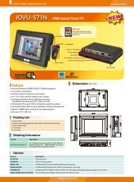
1.2.2 Front Panel<br />
The front panel of the <strong>PPC</strong>-<strong>5190</strong> (Figure 1-1) is a flat panel 19” TFT LCD screen<br />
surrounded by an aluminum frame.
<strong>PPC</strong>-<strong>5190</strong> Flat Panel PC<br />
Figure 1-1: <strong>PPC</strong>-<strong>5190</strong> Front View<br />
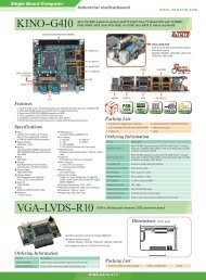
1.2.3 Rear Panel<br />
The rear panel has a fan vent, four VESA standard mounting holes and several retention<br />
screw holes. The VESA mounting holes are circled in Figure 1-2.<br />
Page 22
<strong>PPC</strong>-<strong>5190</strong> Flat Panel PC<br />
Page 23<br />
Figure 1-2: <strong>PPC</strong>-<strong>5190</strong> Rear View<br />
1.2.4 Top Panel<br />
The top panel has two fan vents, eight mounting clamp slots and three retention screws for<br />
securing the drive bay bracket. The retention screws are circled in Figure 1-3 below.<br />
Figure 1-3: <strong>PPC</strong>-<strong>5190</strong> Top View<br />
1.2.5 <strong>PPC</strong>-<strong>5190</strong> Bottom Panel<br />
The bottom panel shown in Figure 1-4 has the following interfaces:
<strong>PPC</strong>-<strong>5190</strong> Flat Panel PC<br />
• 1 x Power input connector<br />
• 1 x Power switch<br />
• 6 x USB connectors<br />
• 1 x Reset button<br />
• 2 x RJ-45 GbE connectors<br />
• 2 x PS/2 keyboard/mouse connector<br />
• 5 x Serial port (COM) connectors<br />
• 1 x PCI add-on card slot<br />
• 1 x Parallel port connector<br />
• 3 x Audio jacks<br />
• 1 x VGA connector<br />
• 1 x Compact Flash slot<br />
Figure 1-4: Bottom View<br />
1.2.6 Left Panel<br />
The left side panel has two fan vents and four retention screws for securing the two<br />
internal fans. The retention screws are circled in Figure 1-5.<br />
Page 24
<strong>PPC</strong>-<strong>5190</strong> Flat Panel PC<br />
Page 25<br />
Figure 1-5: Left View<br />
1.2.7 Right Panel<br />
The right side panel provides access to a slim type CD drive bay and a FDD drive bay<br />
shown in Figure 1-6.<br />
Figure 1-6: Right View<br />
1.3 <strong>PPC</strong>-<strong>5190</strong> Internal Overview<br />
The <strong>PPC</strong>-<strong>5190</strong> internal components are configured in three levels. An elevated platform<br />
on the right side of the chassis supports a HDD, a CD drive and a FDD. On the second<br />
level, below the elevated platform, are a motherboard and a PSU module. The<br />
motherboard and the PSU module are installed on a metal sheet that protects the rear of<br />
the 19” TFT LCD screen. Below the metal sheet is a circuit board that is connected to the<br />
screen and the motherboard. The three levels of components can be seen in Figure 1-7.
<strong>PPC</strong>-<strong>5190</strong> Flat Panel PC<br />
Figure 1-7: Internal Components<br />
1.4 <strong>PPC</strong>-<strong>5190</strong> Specifications<br />
1.4.1 Preinstalled Hardware Components<br />
The <strong>PPC</strong>-<strong>5190</strong> flat panel PC has the following preinstalled components:<br />
• 1 x Motherboard<br />
• 1 x 19” TFT LCD screen<br />
• 1 x Power supply<br />
• 2 x Cooling fans<br />
The technical specifications for these components and the system are shown in the<br />
sections below.<br />
1.4.2 System Specifications<br />
The technical specifications for the <strong>PPC</strong>-<strong>5190</strong> system are listed in Table 1-2.<br />
SPECIFICATION<br />
Front Panel<br />
Chassis<br />
LCD Panel<br />
Resolution<br />
DESCRIPTION<br />
Aluminum Front Panel meets IP 65 standard<br />
Heavy-duty Steel<br />
19” High luminance TFT LCD<br />
1280 x 1024 (SXGA)<br />
Page 26
<strong>PPC</strong>-<strong>5190</strong> Flat Panel PC<br />
Page 27<br />
Brightness<br />
300 cd/m2<br />
Contrast Ratio 700:1<br />
LCD MTBF<br />
Backlight MTBF<br />
50,000 hrs<br />
50,000 hrs<br />
Viewing Angle (H/V) 140/130<br />
Touch Screen<br />
Display<br />
Add-On Card (Optional)<br />
Optional 5-wire resistive type touch screen<br />
with RS-232 interface<br />
Supports Dual Display<br />
Support PCI and CFII<br />
One 2.5” HDD bay with anti-shock<br />
Drive Bay<br />
One slim type CD drive bay<br />
One slim type FDD bay<br />
Input voltage: 90~265V AC, 50~60 Hz<br />
Output rating: 180W<br />
Output voltage: +3.3V@16.8A<br />
Power Supply<br />
+5V@12A<br />
+12V@10A<br />
-12V@0.8A<br />
+5VSB@2A
<strong>PPC</strong>-<strong>5190</strong> Flat Panel PC<br />
Input voltage: 24VDC (18-36VDC)<br />
Output rating: 200W<br />
Output voltage: +3.3V@12A<br />
+5V@12A<br />
+12V@15.4A<br />
-12V@0.5A<br />
+5VSB@2A<br />
Mounting Feature<br />
Color<br />
Operating Temperature<br />
Relative Humidity<br />
Vibration<br />
Shock<br />
Dimensions<br />
Net/Gross Weight<br />
Environment<br />
Panel, Arm, Wall, or Rack/Cabinet<br />
Silver (PANTONE PMS-8001)<br />
0~50˚C<br />
5 ~ 85%, non-condensing<br />
5 - 17Hz, 0.1” double amplitude displacement<br />
17 - 640Hz, 1.5G acceleration, peak to peak<br />
10G Acceleration, peak to peak (11ms)<br />
482.6(W) x 399.3(H) x 115.2(D) mm<br />
12.6/18.2 Kg<br />
RoHS Compliant<br />
Table 1-2: <strong>PPC</strong>-<strong>5190</strong> Specifications<br />
1.4.3 <strong>PPC</strong>-<strong>5190</strong> Motherboard Specifications<br />
The <strong>PPC</strong>-<strong>5190</strong> comes with a POS-8520 motherboard. The technical specifications of the<br />
motherboard are listed in Table 1-3.<br />
SPECIFICATION<br />
CPU<br />
Northbridge<br />
DESCRIPTION<br />
Socket-478 base Intel Pentium 4 / Celeron D<br />
852GME<br />
Page 28
<strong>PPC</strong>-<strong>5190</strong> Flat Panel PC<br />
Page 29<br />
Southbridge<br />
Max. FSB<br />
Memory<br />
BIOS<br />
Display<br />
Expansion Interface<br />
Audio<br />
Ethernet<br />
COM<br />
USB 2.0<br />
Drive Interfaces<br />
LPT<br />
KB/ MS<br />
IrDA<br />
ICH5<br />
533 MHz<br />
2 x DDR 266/333 DIMM socket up to 2GB<br />
AMI BIOS Label<br />
CRT integrated in Intel 852GME<br />
LVDS Dual 18-bit TTL LCD integrated in Intel 852GM<br />
1 x PCI slot<br />
1 x CFII<br />
AC' 97 Codec<br />
2 x Realtek RTL8110SC GbE controller<br />
1 x RS-232/422/485 port<br />
5 x RS-232 ports (1 for optional touch screen)<br />
6 x USB 2.0 ports<br />
2 x SATA drive connectors<br />
2 x ATA 100 channels<br />
2 x PS/2 connector<br />
1 x IrDA interface<br />
Table 1-3: Motherboard Specifications<br />
1.4.4 Flat Panel Screen<br />
The <strong>PPC</strong>-<strong>5190</strong> comes with a 19” TFT LCD monitor at the front of the flat panel PC<br />
(Figure 1-1). The specifications for the LCD monitor are shown in Table 1-4 below.<br />
SPECIFICATION<br />
Model<br />
DESCRIPTION<br />
AUO-M190EG02
<strong>PPC</strong>-<strong>5190</strong> Flat Panel PC<br />
Size 19”<br />
Resolution SXGA (1280 x 1024)<br />
Active Area (mm) 376.32 x 301.06<br />
Pixel Pitch (mm) 0.294<br />
Mode<br />
TN<br />
Number of Colors 16.2M<br />
Color Saturation (%) 72<br />
View Angel (H/V) 160 / 160<br />
Brightness (cd/m2) 300<br />
Contrast Ratio 700 : 1<br />
Response Time (ms) (at 25°C) 6<br />
Power Consumption (W) 28<br />
Interface<br />
2ch LVDS<br />
Supply Voltage (V) 5<br />
Backlight<br />
4 CCFL<br />
Outline Dimensions (mm) 396.0 x 324.0 x 17.5<br />
Weight (g) 2500<br />
Table 1-4: 19” TFT LCD Monitor Specifications<br />
1.4.5 Power Supply<br />
The <strong>PPC</strong>-<strong>5190</strong> flat panel PC comes with either an ACE-4518AP 180W AC-DC 1U, or<br />
ACE-4520C 200W DC 1U RoHS compliant ATX power supply. The PSUs have an MTBF<br />
greater than 100,000 hours.<br />
Page 30
<strong>PPC</strong>-<strong>5190</strong> Flat Panel PC<br />
Page 31<br />
WARNING:<br />
Under no circumstances is the PSU case to be opened. The PSU<br />
module is not user serviceable and there are dangerous high-voltages<br />
inside the case. If there are any problems with the PSU module, please<br />
contact the dealer or reseller immediately.<br />
1.4.5.1 ACE-4518AP Power Supply<br />
Specifications for the ACE-4518AP PSU module are shown in (Table 1-5).<br />
INPUT<br />
Voltage<br />
Frequency<br />
Input Current<br />
Inrush Current<br />
AC90V ~ 265VAC Full Range<br />
47 ~ 63Hz<br />
4A(RMS)@115VAC<br />
2A(RMS)@230VAC<br />
50A Max for 115VAC<br />
80A Max for 230VAC<br />
Voltage (V) +3.3V +5V +12V -12V 5VSB<br />
Min. Load (A) 0.3A 0.3A 1.5A 0A 0A<br />
OUTPUT<br />
Max. Load (A) 16.8A 12A 10A 0.8A 2A<br />
Ripple and Noise (mV) 50mV 50mV 120mV 120mV 50mV<br />
+3.3V & +5V≦61W<br />
+3.3V & +5V & +12V≦160W<br />
GENERAL<br />
Watt<br />
PFC<br />
Hold-up time<br />
180W<br />
Active<br />
17ms minimum<br />
Efficiency 68%<br />
MTBF<br />
100,000hrs
<strong>PPC</strong>-<strong>5190</strong> Flat Panel PC<br />
Temperature<br />
0~50°C (Operating)<br />
-20~80°C (Storage)<br />
Humidity<br />
5 –95% RH, Non-condensing<br />
(Operating & Storage)<br />
Dimension<br />
150mm (W) x 81.5mm (H) x 40.5mm (D)<br />
Table 1-5: ACE-4518AP Power Supply Specifications<br />
1.4.5.2 ACE-4520C Power Supply<br />
Specifications for the ACE-4520C PSU module are shown in (Table 1-6).<br />
INPUT<br />
Voltage<br />
Input Current<br />
Inrush Current<br />
18VDC ~ 36VDC Full Range<br />
15A<br />
100A<br />
Voltage (V) +3.3V +5V +12V -12V 5VSB<br />
Min. Load (A) 0.0A 1.0A 0.5A 0.0A 0.0A<br />
OUTPUT<br />
Max. Load (A) 12A 12A 15.4A 0.5A 2.0A<br />
Ripple and Noise (mV) 50mV 50mV 120mV 120mV 50mV<br />
+3.3V & +5V≦80W; +3.3V & +5V & +12V≦184W<br />
Watt<br />
PFC<br />
Hold-up time<br />
200W<br />
Active<br />
20ms minimum<br />
GENERAL<br />
Efficiency 78%<br />
MTBF<br />
100,000hrs<br />
Temperature<br />
Humidity<br />
Dimension<br />
0~50°C (Operating); -20~80°C (Storage)<br />
5 –95% RH, Non-condensing (Operating & Storage)<br />
150mm (W) x 81.5mm (H) x 40.3mm (D)<br />
Table 1-6: ACE-4520C Power Supply Specifications<br />
Page 32
<strong>PPC</strong>-<strong>5190</strong> Flat Panel PC<br />
Page 33<br />
1.5 Dimensions<br />
The dimensions of the <strong>PPC</strong>-<strong>5190</strong> flat panel PC are shown in Figure 1-8 below.<br />
Figure 1-8: Dimensions (units in mm)
<strong>PPC</strong>-<strong>5190</strong> Flat Panel PC<br />
THIS PAGE IS INTENTIONALLY LEFT BLANK<br />
Page 34
<strong>PPC</strong>-<strong>5190</strong> Flat Panel PC<br />
Page 35<br />
Chapter<br />
2<br />
2 POS-8520<br />
Motherboard
<strong>PPC</strong>-<strong>5190</strong> Flat Panel PC<br />
2.1 Introduction<br />
The <strong>PPC</strong>-<strong>5190</strong> flat screen PC contains a POS-8520 motherboard. The motherboard is the<br />
heart of any computer and is responsible for transmitting, receiving and processing data<br />
as well as driving the different on-board devices. This chapter gives a brief introduction to<br />
the POS-8520 motherboard. For more complete details on the connectors and the<br />
different implementations of the POS-8520, please refer to the POS-8520 user manual.<br />
2.2 CPU Support<br />
The POS-8520 installed in the <strong>PPC</strong>-<strong>5190</strong> supports socket 478, Intel Pentium 4/Celeron D<br />
FSB 533 MHz CPU.<br />
2.3 On-board Chipsets<br />
2.3.1 Northbridge and Southbridge Chipsets<br />
The following chipsets are preinstalled on the board:<br />
• Northbridge: Intel 852GME<br />
• Southbridge: ICH5<br />
The following two sections (Section 2.3.2 and Section 2.3.3) list some of the features of<br />
the 852GME and the ICH5 chipsets. For more information on these two chipsets please<br />
refer to the Intel website.<br />
2.3.2 852GME Northbridge Chipset<br />
The 852GME northbridge chipset comes with the following features:<br />
• Supports the Intel Pentium 4 processor and Intel Celeron processor with Intel<br />
NetBurst® microarchitecture<br />
• 400 MHz or 533 MHz system bus delivers a high-bandwidth connection<br />
between the processor and the platform<br />
• Integrated graphics utilizing Intel® Extreme Graphics 2 technology<br />
• AGP 4X support<br />
Page 36
<strong>PPC</strong>-<strong>5190</strong> Flat Panel PC<br />
Page 37<br />
• Display<br />
o Analog display support<br />
o Dual independent pipe support<br />
o DVO (DVOB and DVOC) support<br />
o Dedicated Local Flat Panel (LFP) LVDS interface<br />
• Intel® Embedded Graphics Drivers<br />
o Graphics interface support<br />
o Multi-monitor support<br />
o Dynamic display-mode support<br />
o Embedded video BIOS<br />
2.3.3 ICH5 Southbridge Chipset<br />
The ICH5 southbridge chipset comes with the following features:<br />
• PCI Bus Interface<br />
o New: Supports PCI Revision 2.3 Specification at 33 MHz<br />
o 6 available PCI REQ/GNT pairs<br />
o One PCI REQ/GNT pair can be given higher arbitration priority (intended<br />
for external 1394 host controller)<br />
o Support for 44-bit addressing on PCI using DAC protocol<br />
• Integrated LAN Controller<br />
o Integrated ASF Management Controller<br />
o WfM 2.0 and IEEE 802.3 Compliant<br />
o LAN Connect Interface (LCI)<br />
o 10/100 Mbit/sec Ethernet Support<br />
• Integrated Serial ATA Host Controllers<br />
o Independent DMA operation on two ports.<br />
o Data transfer rates up to 1.5 Gb/s (150 MB/s).<br />
o RAID Level 0 Support (ICH5R Only)<br />
• Integrated IDE Controller<br />
o Supports “Native Mode” Register and Interrupts<br />
o Independent timing of up to 4 drives<br />
o Ultra ATA/100/66/33, BMIDE and PIO modes<br />
o Tri-state modes to enable swap bay<br />
• Interrupt Controller
<strong>PPC</strong>-<strong>5190</strong> Flat Panel PC<br />
o Supports up to 8 PCI interrupt pins<br />
o Supports PCI 2.3 Message Signaled Interrupts<br />
o Two cascaded 82C59 with 15 interrupts<br />
o Integrated I/O APIC capability with 24 interrupts<br />
o Supports Front Side Bus interrupt delivery<br />
• High-Precision Event Timers<br />
• 1.5 V operation with 3.3 V I/O<br />
o 5V tolerant buffers on IDE, PCI, USB Overcurrent and Legacy signals<br />
• Integrated 1.5 V Voltage Regulator (INTVR) for the Suspend wells<br />
• Enhanced DMA Controller<br />
o Two cascaded 8237 DMA controllers<br />
o PCI DMA: Supports PC/PCI — Includes two PC/PCI REQ#/GNT# pairs<br />
o Supports LPC DMA<br />
o Supports DMA Collection Buffer to provide Type-F DMA performance for<br />
all DMA channels<br />
• Real-Time Clock<br />
2.4 Graphics Support<br />
o 256-byte battery-backed CMOS RAM<br />
o Integrated oscillator components<br />
o Lower Power DC/DC Converter implementation<br />
The Intel® Extreme Graphics 2 is integrated on the Intel® 852GME Northbridge chipset. The<br />
Intel® Extreme Graphics 2 features are listed below.<br />
• Enhanced Rapid Pixel and Texel Rendering: Optimized visual quality and<br />
performance from the addition of hardware to support of texel formatting,<br />
bicubic filter, color blending accuracy, and video mixing render, resulting in<br />
optimized visual quality and performance.<br />
• Zone Rendering 2 Technology: Enhances the performance of zone<br />
rendering by using larger zones and new commands that improve graphics<br />
pipeline efficiency.<br />
• Dynamic Video Memory Technology v2.0: Increases total system<br />
performance by optimizing the efficiency of AGP dynamic video memory by<br />
increasing its size of Video RAM allocation to 96 MB.<br />
Page 38
<strong>PPC</strong>-<strong>5190</strong> Flat Panel PC<br />
Page 39<br />
• Enhanced Intelligent Memory Management: Improves memory bandwidth<br />
efficiency and platform performance by improving the memory management<br />
arbitration between CPU, system memory and graphics memory.<br />
Intel® Extreme Graphics 2 specifications are listed below:<br />
• Enhanced 2D:<br />
o 256-bit internal path<br />
o 8/16/32bpp<br />
o DirectDraw*, GDI, GDI+<br />
o Anti-aliased text support<br />
o Alpha blending<br />
o Alphas stretch blitter<br />
o Hardware alpha blended RGB cursor<br />
o Color space conversion<br />
o 5x2 overlay support<br />
o Rotate, scale and translate operations<br />
• High-performance 3D:<br />
o 256-bit internal path<br />
o 32bpp/ 24ZorW/ 8 Stencil<br />
o DX7*/DX8*/OGL*1.1<br />
o DXTn texture compression<br />
o Up to 4 textures / pixel on a single pass<br />
o Cubic reflection map<br />
o Embossed/DOT3 bump mapping<br />
o Multi-texture<br />
o DOT3 bump-mapping<br />
o Point sprites<br />
• Video and Display:<br />
o DirectShow*/DirectVA*<br />
o Hardware motion compensation support for DVD playback<br />
o 4x2 overlay filter<br />
o 350 MHz DAC frequency<br />
o Maximum DVO pixel rate of up to 330MP/s
<strong>PPC</strong>-<strong>5190</strong> Flat Panel PC<br />
o Flat panel monitors and TV-out support via AGP Digital Display (ADD)<br />
cards<br />
o 350 MHz DAC for 1800x1440 @ 85Hz max CRT resolution or<br />
2048x1536@60Hz max FP resolution<br />
o Synchronous display for dual monitor capabilities<br />
o 350MHz RAMDAC for up to QXGA analog monitor support<br />
o Dual DVO ports for up to QXGA digital display support<br />
o Multiple display types (LVDS, DVI, TV-out, CRT)<br />
2.5 Peripheral Device Interfaces, Connectors, and Slots<br />
The peripheral device connectors, interfaces and slots on the POS-8520 motherboard are<br />
listed in the sections below.<br />
2.5.1 OEM Options<br />
Many of the peripheral device connectors listed below are not connected to any devices.<br />
These connectors are reserved for OEM customizations. For a customized option, please<br />
contact the vendor, reseller or IEI sales representative.<br />
2.5.2 Internal Slots<br />
The slots listed below can all be found on the POS-8520 motherboard.<br />
• 2 x DDR DIMM sockets<br />
• 1 x CFII slot<br />
• 1 x PCI slot<br />
2.5.3 Internal Peripheral Device Connectors<br />
The peripheral device connectors listed below are located on the POS-8520 motherboard.<br />
Pinouts for these connectors can be found in Appendix A.<br />
• 1 x ATX 12V power connector<br />
• 1 x ATX power connector<br />
• 2 x Audio connectors<br />
• 1 x DIO connector<br />
Page 40
<strong>PPC</strong>-<strong>5190</strong> Flat Panel PC<br />
Page 41<br />
• 3 x Fan connectors<br />
• 1 x FDD connector<br />
• 2 x IDE device connectors<br />
• 1 x IrDA connector<br />
• 1 x Keyboard connector<br />
• 1 x PS/2 mouse connector<br />
• 1 x LCD backlight connector<br />
• 1 x LVDS interface connector<br />
• 1 x Multi panel connector<br />
• 1 x Parallel port connector<br />
• 1 x Reset connector<br />
• 2 x Serial ATA connectors<br />
• 6 x Serial port connectors<br />
• 6 x USB connectors<br />
• 1 x VGA connector
<strong>PPC</strong>-<strong>5190</strong> Flat Panel PC<br />
2.5.4 External Peripheral Device Connectors<br />
The peripheral device connectors listed below are located on the rear panel of the<br />
POS-8520 motherboard. Pinouts for these connectors can be found in Appendix A.<br />
• 3 x Audio jack connectors<br />
• 1 x Keyboard connector<br />
• 1 x Mouse connector<br />
• 2 x RJ-45 Ethernet connectors<br />
• 1 x Serial port connector (COM)<br />
• 1 x VGA connector<br />
• 2 x USB ports<br />
Page 42
<strong>PPC</strong>-<strong>5190</strong> Flat Panel PC<br />
Page 43<br />
Chapter<br />
3<br />
3 Installation and<br />
Configuration
<strong>PPC</strong>-<strong>5190</strong> Flat Panel PC<br />
3.1 Installation Precautions<br />
When installing the <strong>PPC</strong>-<strong>5190</strong>, please follow the precautions listed below:<br />
• Turn power off: When installing the <strong>PPC</strong>-<strong>5190</strong> make sure the power is off.<br />
Failing to turn off the power may cause severe injury to the body and/or<br />
damage to the system.<br />
• Certified Engineers: Only certified engineers should install and modify<br />
on-board functions.<br />
• Mounting: The <strong>PPC</strong>-<strong>5190</strong> is a heavy device. When mounting the system onto<br />
a rack, panel, wall or arm please make sure that at least two people are<br />
assisting with the procedure.<br />
• Anti-static Discharge: If a user open the rear panel of the <strong>PPC</strong>-<strong>5190</strong>, to<br />
configure the jumpers or plug in added peripheral devices, ground themselves<br />
first and wear and anti-static wristband.<br />
3.2 Preinstalled Components<br />
The following components are all preinstalled.<br />
• Motherboard<br />
• 19” TFT LCD<br />
• 19” Touch screen (T-R model only)<br />
• Power switch<br />
• Power supply<br />
• Inverter board<br />
• PCI riser card<br />
• System cooling fans<br />
Preinstalled OEM customizations may include the following.<br />
• CPU<br />
• HDD<br />
• FDD<br />
• CD drive<br />
• DIMM<br />
Page 44
<strong>PPC</strong>-<strong>5190</strong> Flat Panel PC<br />
Page 45<br />
Removal and reinstallation of some of the components are described in Chapter 4.<br />
3.3 Installation and Configuration Steps<br />
The following installation steps must be followed.<br />
Step 1: Unpack the <strong>PPC</strong>-<strong>5190</strong>.<br />
Step 2: Set the jumper settings.<br />
Step 3: Install HDD, FDD and CD drive.<br />
Step 4: Mount the <strong>PPC</strong>-<strong>5190</strong> flat panel PC.<br />
Step 5: Connect peripheral devices to the bottom panel of the <strong>PPC</strong>-<strong>5190</strong>.<br />
Step 6: Configure the system.Step 0:<br />
3.4 Unpacking<br />
To unpack the <strong>PPC</strong>-<strong>5190</strong> flat panel PC, follow the steps below:<br />
WARNING!<br />
The front side LCD screen has a protective plastic cover stuck to the<br />
screen. Only remove the plastic cover after the <strong>PPC</strong>-<strong>5190</strong> flat panel PC has<br />
been properly installed. The plastic cover ensures the screen is protected<br />
during the installation process.<br />
Step 1: Use box cutters, a knife or a sharp pair of scissors to cut the tape that seals the<br />
top side of the external (second) box.<br />
Step 2: Open the external (second) box.<br />
Step 3: Use box cutters, a knife or a sharp pair of scissors to cut the tape that seals the<br />
top side of the internal (first) box.<br />
Step 4: Lift the monitor out of the boxes.
<strong>PPC</strong>-<strong>5190</strong> Flat Panel PC<br />
Step 5: Remove both polystyrene ends, one from each side.<br />
Step 6: Make sure all the components listed in the packing list are present.Step 0:<br />
3.4.1 Packing List<br />
The <strong>PPC</strong>-<strong>5190</strong> flat panel PC is shipped with the following components:<br />
3.5 Jumper Settings<br />
• 1 x Carton<br />
• 1 x Power cord<br />
• 1 x Screw kit<br />
• 1 x HDD IDE cable (44 pin + 2 x 40 pin)<br />
• 1 x HDD IDE cable (44 pin + 40 pin)<br />
• 1 x HDD SATA cable<br />
• 1 x Driver CD (including user manual)<br />
• 1 x CPU cooler<br />
• 1 x CD-ROM installation kit<br />
• 1 x FDD installation kit<br />
• 1 x HDD bracket<br />
• 1 x Jumper pack<br />
• 1 x Wall-mounting kit<br />
• 1 x Panel-mounting kit<br />
• 1 x Touch screen driver CD (T-R model only)<br />
• 1 x Touch pen (T-R model only)<br />
NOTE:<br />
These jumper settings and the jumper locations are described in detail in the<br />
user manual that came with the POS-8520 motherboard. Please refer to the<br />
manual for more detailed descriptions of the jumper settings.<br />
Page 46
<strong>PPC</strong>-<strong>5190</strong> Flat Panel PC<br />
Page 47<br />
NOTE:<br />
A jumper is a metal bridge that is used to close an electrical circuit. It consists<br />
of two metal pins and a small metal clip (often protected by a plastic cover)<br />
that slides over the pins to connect them. To CLOSE/SHORT a jumper means<br />
connecting the pins of the jumper with the plastic clip and to OPEN a jumper<br />
means removing the plastic clip from a jumper.<br />
The POS-8520 comes with fifteen jumpers (Table 3-1).<br />
Jumper Type Label<br />
Clear CMOS Setup 3-pin header JP1<br />
COM# RI and Voltage Selection<br />
3-pin header<br />
JP6<br />
JP7<br />
JP8<br />
JP9<br />
JP13<br />
JP14<br />
JP15<br />
JP16<br />
COM2 RS-232/422/485 Setup<br />
12-pin header<br />
6-pin header<br />
JP10<br />
JP20<br />
CompactFlash Card Setup 2-pin header JP12<br />
CPU Voltage Setting 10-pin header S3<br />
Keyboard/Mouse Power Source 3-pin header JP18<br />
LCD Voltage Select 6-pin header JP2<br />
Table 3-1: Onboard Jumpers
<strong>PPC</strong>-<strong>5190</strong> Flat Panel PC<br />
3.5.1 Remove the Back Cover<br />
The back cover is secured to the chassis with fourteen retention screws, eleven on the<br />
rear panel and two on the bottom panel (Figure 3-1). Remove the fourteen retention<br />
screws and lift the cover off the <strong>PPC</strong>-<strong>5190</strong>.<br />
Figure 3-1: Back Cover Retention Screws<br />
Page 48
<strong>PPC</strong>-<strong>5190</strong> Flat Panel PC<br />
Page 49<br />
3.5.2 CF Card Setup (JP12)<br />
The CF Card Setup jumper configures a CF card as either the slave or the master.<br />
JP12<br />
Open<br />
Close<br />
DESCRIPTION<br />
Slave (Default)<br />
Master<br />
Table 3-2: CF Card Setup Jumper Settings<br />
3.5.3 Clear CMOS Setup (JP1)<br />
If the motherboard fails to boot due to improper BIOS settings, use this jumper to clear the<br />
CMOS data and reset the system BIOS information. To do this, use the jumper cap to<br />
close pins 2 and 3 for a few seconds then reinstall the jumper clip back to pins 1 and 2.<br />
If the “CMOS Settings Wrong” message displays during the boot up process, try to correct<br />
the fault by pressing the F1 to enter the CMOS Setup menu. Then do one of the following:<br />
• Enter the correct CMOS setting<br />
• Load Optimal Defaults<br />
After one of the above has been done, save the changes and exit the CMOS Setup menu.<br />
JP1<br />
DESCRIPTION<br />
1-2 closed Normal (Default)<br />
2-3 closed Clear CMOS<br />
Table 3-3: Clear CMOS Jumper Settings
<strong>PPC</strong>-<strong>5190</strong> Flat Panel PC<br />
3.5.4 COM2 Port RS232/422/485 Selection (JP10, JP20)<br />
The COM Port jumper configures the COM2 serial port.<br />
JP10 JP20 DESCRIPTION<br />
1-2,4-5,7-8,10-11 closed 1-3 closed RS232 (default)<br />
2-3,5-6,8-9,11-12 closed 3-5, 2-4 closed RS422<br />
2-3,5-6,8-9,11-12 closed 3-5, 4-6 closed RS485<br />
Table 3-4: COM2 Port Jumper Settings<br />
3.5.5 COM port RI and Voltage Selection<br />
Use JP7 and JP9 to set pin 9 of COM1 as signal RI or voltage source.<br />
JP9<br />
DESCRIPTION<br />
2-3 closed COM1 RI PIN Use RI<br />
1-2 closed COM1 RI PIN Use Voltage<br />
Table 3-5: COM1 RI and Voltage Selection Jumper<br />
JP7<br />
DESCRIPTION<br />
2-3 closed COM1 RI PIN Use Voltage +12V<br />
1-2 closed COM1 RI PIN Use Voltage +5V<br />
Table 3-6: COM1 RI Voltage Selection Jumper<br />
NOTE:<br />
The use of pin 2-3 or pin 1-2 of JP7 does not make any difference when pin 2-3<br />
of JP9 is in use.<br />
Use JP6 and JP8 to set pin 9 of COM2 as signal RI or voltage source.<br />
Page 50
<strong>PPC</strong>-<strong>5190</strong> Flat Panel PC<br />
Page 51<br />
JP8<br />
DESCRIPTION<br />
2-3 closed COM2 RI PIN Use RI<br />
1-2 closed COM2 RI PIN Use Voltage<br />
Table 3-7: COM2 RI and Voltage Selection Jumper<br />
JP6<br />
DESCRIPTION<br />
2-3 closed COM2 RI PIN Use Voltage +12V<br />
1-2 closed COM2 RI PIN Use Voltage +5V<br />
Table 3-8: COM2 RI Voltage Selection Jumper<br />
Use JP13 and JP15 to set pin 9 of COM3 as signal RI or voltage source.<br />
JP15<br />
DESCRIPTION<br />
2-3 closed COM3 RI PIN Use RI<br />
1-2 closed COM3 RI PIN Use Voltage<br />
Table 3-9: COM3 RI and Voltage Selection Jumper<br />
JP13<br />
DESCRIPTION<br />
2-3 closed COM3 RI PIN Use Voltage +12V<br />
1-2 closed COM3 RI PIN Use Voltage +5V<br />
Table 3-10: COM3 RI Voltage Selection Jumper<br />
Use JP14 and JP16 to set pin 9 of COM4 as signal RI or voltage source.<br />
JP16<br />
DESCRIPTION<br />
2-3 closed COM4 RI PIN Use RI<br />
1-2 closed COM4 RI PIN Use Voltage<br />
Table 3-11: COM4 RI and Voltage Selection Jumper
<strong>PPC</strong>-<strong>5190</strong> Flat Panel PC<br />
JP14<br />
DESCRIPTION<br />
2-3 closed COM4 RI PIN Use Voltage +12V<br />
1-2 closed COM4 RI PIN Use Voltage +5V<br />
Table 3-12: COM4 RI Voltage Selection Jumper<br />
3.5.6 Keyboard and Mouse Power Source Setting (JP18)<br />
JP18<br />
DESCRIPTION<br />
1-2 closed VCC (default)<br />
2-3 closed 5VSB<br />
Table 3-13: Keyboard and Mouse Power Source Setting<br />
3.5.7 LCD Voltage Setup (JP2)<br />
WARNING:<br />
Do not change this voltage. This voltage has been preset and is compatible<br />
with the currently installed 17” TFT LCD screen. Change this jumper setting<br />
may cause damage to the system.<br />
The LCD Voltage Setup jumper sets the voltage for the LCD screen. This setting MUST<br />
NOT be changed.<br />
JP2<br />
DESCRIPTION<br />
1-2 closed +3.3V (default)<br />
3-4 closed +5V<br />
5-6 closed +12V<br />
Table 3-14: LCD Voltage Setup Jumper Settings<br />
Page 52
<strong>PPC</strong>-<strong>5190</strong> Flat Panel PC<br />
Page 53<br />
3.6 HDD, FDD and CD Drive Installation<br />
3.6.1 HDD Installation<br />
To install a HDD, please follow the steps below:<br />
Step 1: Remove the back cover (Section 3.5.1).<br />
Step 2: The HDD bracket is attached to the elevated platform by four retention screws.<br />
Remove the four retention screws from the elevated platform (Figure 3-2).<br />
Figure 3-2: HDD Retention Screws<br />
Step 3: Attach the HDD bracket to the HDD. To do this, align the four retention screw<br />
holes in both side of HDD bracket with the retention screw holes on the side of<br />
the HDD. Insert two retention screws into the bracket on both sides of the HDD.<br />
Step 4: Install the HDD into the <strong>PPC</strong>-<strong>5190</strong> by aligning the retention screw holes in the<br />
base of the HDD bracket with the retention screw holes on the elevated platform.<br />
Insert the four retention screws into the base of the HDD bracket.<br />
Step 5: Connect the IDE/SATA cable from the IDE/SATA connector on the motherboard<br />
to the rear of HDD.Step 0:
<strong>PPC</strong>-<strong>5190</strong> Flat Panel PC<br />
3.6.2 FDD Installation<br />
To install the FDD, please follow the steps below:<br />
Step 1: Remove the back cover (Section 3.5.1).<br />
Step 2: The FDD bracket is attached to the elevated platform by two retention screws<br />
(Figure 3-3). Remove the two retention screws from the elevated platform.<br />
Step 3: Remove the FDD bracket by sliding toward the HDD.<br />
Figure 3-3: FDD Retention Screws<br />
Step 4: Attach the FDD adapter to the FDD by aligning the two retention screw holes in<br />
the FDD adapter with the retention screw holes on the rear side of the FDD<br />
bracket. Insert two retention screws into the adapter (Figure 3-4). Connect the<br />
FDD adapter and FDD with ribbon cable.<br />
Page 54
<strong>PPC</strong>-<strong>5190</strong> Flat Panel PC<br />
Page 55<br />
Figure 3-4: FDD Adapter and FDD Bracket Installation<br />
Step 5: Attach the FDD bracket to the FDD. To do this, align the four retention screw<br />
holes in the FDD bracket with the retention screw holes on the sides of the FDD.<br />
Insert four retention screws into the bracket of the FDD.<br />
Step 6: Reinstall the FDD bracket onto the elevated platform with the previously<br />
removed two retention screws.<br />
Step 7: Connect the FDD ribbon cable and the power cable from the connectors on the<br />
motherboard and the PSU to the rear of the FDD.Step 0:<br />
3.6.3 CD Drive Installation<br />
To install a CD drive, please follow the steps below.<br />
Step 1: Attach a CD drive adapter to a CD drive by aligning the two retention screw<br />
holes in the CD drive adapter with the retention screw holes on the rear side of<br />
the CD drive.<br />
Step 2: Place two spacers between the CD drive and CD drive adapter.<br />
Step 3: Insert two retention screws and secure the adapter to the CD drive (Figure 3-5).
<strong>PPC</strong>-<strong>5190</strong> Flat Panel PC<br />
Figure 3-5: CD Drive Adapter Installation<br />
Step 4: Remove the back cover of the <strong>PPC</strong>-<strong>5190</strong> (see Section 3.5.1).<br />
Step 5: The CD drive blank plate assembly is attached to the rear panel by two retention<br />
screws (Figure 3-6).<br />
Figure 3-6: CD Drive Retention Screws<br />
Remove the two retention screws from the bottom panel and slide the CD drive<br />
blank plate assembly toward the PCI riser card until it can be lifted out of the<br />
chassis (Figure 3-7).<br />
Page 56
<strong>PPC</strong>-<strong>5190</strong> Flat Panel PC<br />
Page 57<br />
Figure 3-7: Remove CD Drive<br />
Step 6: The CD drive blank plate assembly consists of a blank plate and two brackets<br />
that attach the assembly to the chassis. The two brackets each have two screws<br />
that attach them to the blank plate. Remove the four screws that attach the<br />
brackets to the blank plate. Figure 3-8 shows the underside of the CD drive<br />
blank plate assembly with the four screws to be removed.<br />
Figure 3-8: CD Drive Blank Plate Assembly<br />
Step 7: Attach the two brackets to a CD drive with the four previously removed screws.<br />
Be sure to orient the brackets properly before attaching them to the CD drive.<br />
Figure 3-9 shows two views of a CD drive with the brackets attached and the<br />
proper retention screws to use.
<strong>PPC</strong>-<strong>5190</strong> Flat Panel PC<br />
Figure 3-9: CD Drive Blank Plate Assembly<br />
WARNING!<br />
The two screws (black M2*3) shown in the left image of Figure 3-9 are<br />
different from the two screws (silver M2*2) shown in the right. Please<br />
secure the correct screws into the CD drive according to the images shown<br />
in the Figure 3-9.<br />
Step 8: Slide the CD drive into the <strong>PPC</strong>-<strong>5190</strong> and align the two retention screw holes in<br />
the side of the CD drive bracket with the retention screw holes on the bottom<br />
panel.<br />
Step 9: Reinsert the two previously removed retention screws.<br />
Step 10: Connect the CD ribbon cable and the power cable from the connectors on the<br />
motherboard and the PSU to the rear of the CD drive. Figure 3-10 shows a<br />
properly installed CD drive.Step 0:<br />
Page 58
<strong>PPC</strong>-<strong>5190</strong> Flat Panel PC<br />
Page 59<br />
Figure 3-10: CD Drive Installed<br />
3.7 Mounting the System<br />
WARNING!<br />
When mounting the <strong>PPC</strong>-<strong>5190</strong> flat panel PC onto an arm, wall or into a<br />
panel, it is advisable to have more than one person help with the<br />
installation to prevent accidental damage to the panel and avoid personal<br />
injury.<br />
The methods of mounting the <strong>PPC</strong>-<strong>5190</strong> are:<br />
• Wall mounting<br />
• Panel mounting<br />
• Arm mounting<br />
• Rack mounting<br />
The mounting methods are fully described below.<br />
3.7.1 Wall Mounting<br />
To mount the <strong>PPC</strong>-<strong>5190</strong>G flat panel PC onto a wall, please follow the steps below.
<strong>PPC</strong>-<strong>5190</strong> Flat Panel PC<br />
Step 1: Select the location on the wall for the wall-mounting bracket.<br />
Step 2: Carefully mark the locations of the four bracket screw holes on the wall.<br />
Step 3: Drill four pilot holes at the marked locations on the wall for the bracket retention<br />
screws.<br />
Step 4: Align the wall-mounting bracket screw holes with the pilot holes.<br />
Step 5: Secure the mounting-bracket to the wall by inserting the retention screws into<br />
the four pilot holes and tightening them (see Figure 3-11).<br />
Figure 3-11: Wall-mounting Bracket<br />
Step 6: Insert the four monitor mounting screws provided in the wall mounting kit into the<br />
four screw holes on the real panel of the monitor and tighten until the screw<br />
shank is secured against the rear panel (see Figure 3-12).<br />
Step 7: Align the mounting screws on the monitor rear panel with the mounting holes on<br />
the bracket.<br />
Step 8: Carefully insert the screws through the holes and gently pull the monitor<br />
downwards until the monitor rests securely in the slotted holes (see Figure<br />
Page 60
<strong>PPC</strong>-<strong>5190</strong> Flat Panel PC<br />
Page 61<br />
3-12). Ensure that all four of the mounting screws fit snuggly into their respective<br />
slotted holes.<br />
NOTE:<br />
In the diagram below the bracket is already installed on the wall.<br />
Figure 3-12: Mount the Chassis<br />
Step 9: Secure the panel PC with the wall-mounting kit. To do this, stick the protective<br />
cushion to the wall-mounting kit first. Then, put the wall-mounting kit on the top<br />
panel of the panel PC. Carefully mark the location of the wall-mounting kit screw<br />
holes on the wall. Drill a pilot hole at the marked location on the wall. Secure the<br />
wall-mounting kit to the wall by inserting a retention screw into the pilot hole on<br />
the wall (Figure 3-13). This step is to avoid the panel PC being pushed apart<br />
from the wall-mounting bracket accidentally. Step 0:
<strong>PPC</strong>-<strong>5190</strong> Flat Panel PC<br />
Figure 3-13: Secure the Chassis<br />
3.7.2 Panel/ Mounting<br />
To mount the <strong>PPC</strong>-<strong>5190</strong> flat panel PC into a panel, please follow the steps below.<br />
NOTE:<br />
The maximum panel thickness should be no more than 6mm.<br />
Step 1: Select the position on the panel to mount the <strong>PPC</strong>-<strong>5190</strong>.<br />
Step 2: Cut out a section of the panel that corresponds to the rear panel dimensions of<br />
the <strong>PPC</strong>-<strong>5190</strong>. Take care that the panel section that is cut out is smaller than the<br />
overall size of the metal frame that surrounds the <strong>PPC</strong>-<strong>5190</strong> but just large<br />
enough for the rear panel of the <strong>PPC</strong>-<strong>5190</strong> to fit through (Figure 3-14).<br />
Page 62
<strong>PPC</strong>-<strong>5190</strong> Flat Panel PC<br />
Page 63<br />
Figure 3-14: Cut the Panel<br />
Step 3: Slide the <strong>PPC</strong>-<strong>5190</strong> through the hole until the metal frame is flush against the<br />
panel.<br />
Step 4: Insert the panel mounting clamps into the pre-formed holes along the edges of<br />
the <strong>PPC</strong>-<strong>5190</strong>, behind the metal frame (Figure 3-15). Refer to the mounting kit<br />
packing list for the required number of mounting clamps.<br />
Figure 3-15: Panel Mounting Clamp Positions
<strong>PPC</strong>-<strong>5190</strong> Flat Panel PC<br />
Step 5: Tighten the screws that pass through the panel mounting clamps until the plastic<br />
caps at the front of all the screws are firmly secured to the panel (Figure 3-16).Step 0:<br />
Figure 3-16: Tighten the Panel Mounting Clamp Screws<br />
3.7.3 Rack and Cabinet Installation<br />
To mount the <strong>PPC</strong>-<strong>5190</strong> monitor into a rack/cabinet, please follow the steps below.<br />
Step 1: Secure the rack mounting bracket to two sides of the monitor using the supplied<br />
retention screws (Figure 3-17). Each bracket requires four screws.<br />
Step 2: Secure the rack mounting bracket to the rack by inserting and tightening the<br />
supplied mounting nuts and bolts (Figure 3-17). Each bracket requires three<br />
nuts and bolts for installation.Step 0:<br />
Page 64
<strong>PPC</strong>-<strong>5190</strong> Flat Panel PC<br />
Page 65<br />
Figure 3-17: Rack Mounting<br />
3.7.4 Arm Mounting<br />
The <strong>PPC</strong>-<strong>5190</strong> is VESA (Video Electronics Standards Association) compliant and can be<br />
mounted on an arm with a 100mm interface pad. To mount the <strong>PPC</strong>-<strong>5190</strong> on an arm,<br />
please follow the steps below.<br />
Step 1: The arm is a separately purchased item. Please correctly mount the arm onto<br />
the surface it uses as a base. To do this, refer to the installation documentation<br />
that came with the mounting arm.<br />
NOTE:<br />
When purchasing the arm please ensure that it is VESA compliant and that<br />
the arm has a 100mm interface pad. If the mounting arm is not VESA<br />
compliant, it cannot be used to support the <strong>PPC</strong>-<strong>5190</strong> flat panel PC.<br />
Step 2: Once the mounting arm has been firmly attached to its surface, lift the <strong>PPC</strong>-<strong>5190</strong><br />
flat panel PC onto the interface pad of the mounting arm.<br />
Step 3: Align the retention screw holes on the mounting arm interface with those in the<br />
<strong>PPC</strong>-<strong>5190</strong> flat panel PC. The <strong>PPC</strong>-<strong>5190</strong> flat panel PC arm mount retention
<strong>PPC</strong>-<strong>5190</strong> Flat Panel PC<br />
screw holes are shown in Figure 3-18.<br />
Figure 3-18: Arm Mount Retention Screw Holes<br />
Step 4: Secure the <strong>PPC</strong>-<strong>5190</strong> to the interface pad by inserting four retention screws<br />
through the mounting arm interface pad and into the <strong>PPC</strong>-<strong>5190</strong> flat panel PC.Step<br />
0:<br />
3.8 External Peripheral Interface Connectors<br />
3.8.1 LCD Panel Connection<br />
A conventional CRT VGA 15-pin female D-SUB connector is located on the bottom panel<br />
to connect the <strong>PPC</strong>-<strong>5190</strong> flat panel PC to a second monitor.<br />
NOTE:<br />
To use the dual screen option, please configure this option in the Intel® Extreme<br />
Graphics configuration settings. To do this, open the Control Panel, locate the<br />
Intel® Extreme Graphics icon and click on it. Once opened, an option for Multiple<br />
Display is available. Select this option and select notebook as the primary device.<br />
3.8.2 Ethernet Connection<br />
The two external peripheral interface RJ-45 connectors can be connected to an external<br />
LAN to provide Internet connectivity to the flat panel PC.<br />
Page 66
<strong>PPC</strong>-<strong>5190</strong> Flat Panel PC<br />
Page 67<br />
3.8.3 USB Connection<br />
The external peripheral interface USB connectors provide easy and quick access to<br />
external USB devices. The external peripheral interface USB connectors are a standard<br />
connector and can easily be connected to other USB devices.<br />
3.8.4 Keyboard and Mouse Connection<br />
Two PS/2 connectors on the external peripheral interface panel facilitate the connection of<br />
a mouse and a keyboard. To connect either device, plug the PS/2 connector at the end of<br />
the keyboard or mouse cable into the corresponding PS/2 connector on the external<br />
peripheral interface panel.<br />
3.8.5 Parallel Port Connection<br />
The parallel port is typically connected to a printer, but can also be connected to other<br />
parallel devices.<br />
3.8.6 Serial Port Connection<br />
The external peripheral interface panel serial connectors provide easy and quick access to<br />
external serial devices.<br />
3.8.7 Audio Port Connection<br />
The external peripheral interface panel audio ports provide line in, line out and speaker<br />
connectivity.
<strong>PPC</strong>-<strong>5190</strong> Flat Panel PC<br />
THIS PAGE IS INTENTIONALLY LEFT BLANK<br />
Page 68
<strong>PPC</strong>-<strong>5190</strong> Flat Panel PC<br />
Page 69<br />
Chapter<br />
4<br />
4 System Maintenance
<strong>PPC</strong>-<strong>5190</strong> Flat Panel PC<br />
4.1 System Maintenance Introduction<br />
The following system components may require maintenance.<br />
• Motherboard<br />
• DIMM module<br />
• PSU module<br />
• Cooling fans<br />
If these components fail, they must be replaced. Please contact the system reseller or<br />
vendor to purchase replacement parts. Replacement instructions for the above listed<br />
components are described below.<br />
4.2 Motherboard Replacement<br />
A user cannot replace a motherboard. If the motherboard fails it must be shipped back to<br />
IEI to be replaced. If the system motherboard has failed, please contact the system vendor,<br />
reseller or an IEI sales person directly.<br />
4.3 Back Cover Removal and Elevated Platform Detachment<br />
WARNING!<br />
BEFORE REMOVING THE BACK COVER, MAKE SURE ALL POWER<br />
TO THE SYSTEM HAS BEEN DISCONNECTED. Failing to do so may<br />
cause severe damage to the <strong>PPC</strong>-<strong>5190</strong> and injury to the user.<br />
Page 70
<strong>PPC</strong>-<strong>5190</strong> Flat Panel PC<br />
Page 71<br />
WARNING!<br />
PLEASE TAKE ANTISTATIC PRECAUTIONS WHEN WORKING WITH<br />
THE INTERNAL COMPONENTS. The interior of the <strong>PPC</strong>-<strong>5190</strong> contains<br />
very sensitive electronic components. These components are easily<br />
damaged by electrostatic discharge (ESD). Before working with the internal<br />
components, make sure all anti-static precautions described earlier have<br />
been observed.<br />
4.3.1 Back Cover Removal<br />
Please read the warnings at the beginning of Section 4.3 before attempting to remove the<br />
<strong>PPC</strong>-<strong>5190</strong> back cover.<br />
To access the panel PC internal components, the back cover must be removed. To<br />
remove the back cover, please follow the steps below.<br />
Step 1: Remove the <strong>PPC</strong>-<strong>5190</strong> from its mount (panel, wall, rack, arm, etc.).<br />
Step 2: The back cover is secured to the chassis with fourteen retention screws, eleven<br />
on the back cover and two on the bottom panel (Figure 4-1). Remove the<br />
retention screws and lift the cover off the <strong>PPC</strong>-<strong>5190</strong>. Step 0:
<strong>PPC</strong>-<strong>5190</strong> Flat Panel PC<br />
Figure 4-1: Rear Cover Retention Screws (Real Panel)<br />
4.3.2 Detaching the Elevated Platform<br />
Please read the warnings at the beginning of Section 4.3 before attempting to access any<br />
<strong>PPC</strong>-<strong>5190</strong> internal components.<br />
The elevated platform supports the FDD, CD drive and HDD. Back cover removal is<br />
discussed in Section 4.3.1. To detach the elevated platform, please follow the steps<br />
below.<br />
Step 1: Disconnect all FDD, CD drive and HDD cabling.<br />
Page 72
<strong>PPC</strong>-<strong>5190</strong> Flat Panel PC<br />
Page 73<br />
Step 2: Remove the CD drive retention screws from the bottom panel (Figure 4-2).<br />
Figure 4-2: CD Drive Retention Screws<br />
Step 3: The elevated platform is secured to the chassis with twelve retention screws,<br />
two on the internal platform (Figure 4-3), three on the top panel (Figure 4-4),<br />
three on the right panel (Figure 4-5), two on the bottom panel (Figure 4-6) and<br />
two on the PCI riser card (Figure 4-7). Remove the retention screws and lift the<br />
elevated platform out of the chassis. Step 0:<br />
Figure 4-3: Internal Elevated Platform Retention Screws<br />
Figure 4-4: Elevated Platform Retention Screws (Top Panel)
<strong>PPC</strong>-<strong>5190</strong> Flat Panel PC<br />
Figure 4-5: Elevated Platform Retention Screws (Right Panel)<br />
Figure 4-6: Elevated Platform Retention Screws (Bottom Panel)<br />
Figure 4-7: Elevated Platform Retention Screws (PCI Riser Card)<br />
4.4 DIMM Replacement<br />
Please read the warnings at the beginning of Section 4.3 before attempting to access any<br />
<strong>PPC</strong>-<strong>5190</strong> internal components.<br />
Page 74
<strong>PPC</strong>-<strong>5190</strong> Flat Panel PC<br />
Page 75<br />
To install/replace the DIMM modules please follow the steps below.<br />
Step 1: Remove the back cover (Section 4.3.1).<br />
Step 2: Locate the DIMM socket on the motherboard near the right of the chassis. Push<br />
down on the white levers of the socket until the DIMM module is dislodged from<br />
the socket (Figure 4-8).<br />
Figure 4-8: DIMM Socket Clip Locations<br />
Step 3: Slowly slide the new DIMM module along the plastic guides at both ends of the<br />
socket. Press the DIMM module down into the socket until it clicks into position<br />
and the two handles have automatically locked the memory module into place.Step 0:<br />
4.5 PSU Module Replacement<br />
Please read the warnings at the beginning of Section 4.3 before attempting to access any<br />
<strong>PPC</strong>-<strong>5190</strong> internal components.<br />
If the PSU module has been damaged it must be replaced. To replace the PSU module,<br />
please follow the steps below.<br />
4.5.1 Remove the Old PSU<br />
Step 1: Remove the back cover (Section 4.3.1).
<strong>PPC</strong>-<strong>5190</strong> Flat Panel PC<br />
Step 2: Detach and remove the elevated platform (see Section 4.3.2).<br />
Step 3: Disconnect all PSU connections including those to the motherboard (Figure 4-9)<br />
and any disk drives.<br />
Figure 4-9: PSU Motherboard Connectors<br />
The PSU module is secured to the <strong>PPC</strong>-<strong>5190</strong> flat panel PC with six retention screws, two<br />
connect to the bottom panel (Figure 4-10), two connect to the internal PSU bracket<br />
(Figure 4-12) which is connected to the chassis by two screws (Figure 4-11).<br />
Step 4: Remove the PSU retention screws from the bottom panel (Figure 4-10).<br />
Figure 4-10: PSU Bottom Panel Retention Screws<br />
Step 5: Remove the retention screws that connect the PSU bracket to the chassis<br />
(Figure 4-11).<br />
Page 76
<strong>PPC</strong>-<strong>5190</strong> Flat Panel PC<br />
Page 77<br />
Figure 4-11: PSU Bracket to Chassis Retention Screws<br />
Step 6: Remove the retention screws that connect the PSU to the PSU bracket<br />
(Figure 4-12).Step 0:<br />
Figure 4-12: PSU Bracket Retention Screws<br />
4.5.2 Install the New PSU<br />
To install a new PSU module, please follow the steps below.<br />
Step 1: Attach the PSU bracket to the PSU module with the previously removed<br />
retention screws.<br />
Step 2: Insert the PSU module and bracket assembly into the chassis and attach the<br />
PSU bracket to the chassis with the previously removed retention screws.<br />
Step 3: Secure the PSU module to the chassis by reinserting the previously removed<br />
retention screws through the bottom panel.
<strong>PPC</strong>-<strong>5190</strong> Flat Panel PC<br />
Step 4: Bundle the cables of the new PSU module and secure them with a plastic tie<br />
similar to the old PSU module.<br />
Step 5: Reconnect all previously disconnected power connectors to the motherboard<br />
and disk drives.<br />
Step 6: Reattach the elevated platform.<br />
Step 7: Replace the back cover.Step 0:<br />
4.6 System Cooling Fan Replacement<br />
Please read the warnings at the beginning of Section 4.3 before attempting to access any<br />
<strong>PPC</strong>-<strong>5190</strong> internal components.<br />
If the system cooling fans have been damaged, they must be replaced. To replace the<br />
system cooling fans, please follow the steps below.<br />
4.6.1 Remove the Old System Cooling Fans<br />
Step 1: Remove the back cover (Section 4.3.1).<br />
Step 2: Detach and remove the elevated platform (see Section 4.3.2).<br />
Step 3: Disconnect the system cooling fans from the motherboard (Figure 4-13).<br />
Figure 4-13: System Cooling Fans Motherboard Connector<br />
Page 78
<strong>PPC</strong>-<strong>5190</strong> Flat Panel PC<br />
Page 79<br />
Step 4: Remove the system cooling fans retention screws from the left panel<br />
(Figure 4-14).<br />
Figure 4-14: System Cooling Fans Left Panel Retention Screws<br />
Step 5: Remove the system cooling fans from the chassis. Step 0:<br />
4.6.2 Install the New System Cooling Fans<br />
To install the new system cooling fans, please follow the steps below.<br />
Step 1: Insert the system cooling fans into the chassis and attach to the left panel with<br />
the previously removed retention screws.<br />
Step 2: Rebundle the new fan wires and tie them to the chassis like the old fan wires.<br />
Step 3: Reconnect the new fan connector to the motherboard.<br />
Step 4: Reattach the elevated platform.<br />
Step 5: Replace the back cover.Step 0:
<strong>PPC</strong>-<strong>5190</strong> Flat Panel PC<br />
THIS PAGE IS INTENTIONALLY LEFT BLANK<br />
Page 80
<strong>PPC</strong>-<strong>5190</strong> Flat Panel PC<br />
Page 81<br />
Chapter<br />
5<br />
5 AMI BIOS
<strong>PPC</strong>-<strong>5190</strong> Flat Panel PC<br />
5.1 Introduction<br />
A licensed copy of AMI BIOS is preprogrammed into the ROM BIOS. The BIOS setup<br />
program allows users to modify the basic system configuration. This chapter describes<br />
how to access the BIOS setup program and the configuration options that may be<br />
changed.<br />
5.1.1 Starting Setup<br />
The AMI BIOS is activated when the computer is turned on. The setup program can be<br />
activated in one of two ways.<br />
1. Press the DELETE key as soon as the system is turned on or<br />
2. Press the DELETE key when the “Press Del to enter SETUP”<br />
message appears on the screen. 0.<br />
If the message disappears before the DELETE key is pressed, restart the computer and try<br />
again.<br />
5.1.2 Using Setup<br />
Use the arrow keys to highlight items, press ENTER to select, use the “+” and “-“ keys to<br />
change entries, press F1 for help and press ESC to quit. Navigation keys are shown in.<br />
Key<br />
Function<br />
Up arrow Move to previous item<br />
Down arrow Move to next item<br />
Left arrow Move to the item on the left hand side<br />
Right arrow Move to the item on the right hand side<br />
Esc key Main Menu – Quit and not save changes into CMOS<br />
Status Page Setup Menu and Option Page Setup Menu --<br />
Exit current page and return to Main Menu<br />
“+” key Increase the numeric value or make changes<br />
“-“ key Decrease the numeric value or make changes<br />
Page 82
<strong>PPC</strong>-<strong>5190</strong> Flat Panel PC<br />
Page 83<br />
Key<br />
F1 key<br />
F2 /F3 key<br />
F10 key<br />
Function<br />
General help, only for Status Page Setup Menu and Option<br />
Page Setup Menu<br />
Change color from total 16 colors. F2 to select color<br />
forward.<br />
Save all the CMOS changes, only for Main Menu<br />
Table 5-1: BIOS Navigation Keys<br />
5.1.3 Getting Help<br />
When F1 is pressed a small help window describing the appropriate keys to use and the<br />
possible selections for the highlighted item appears. To exit the Help Window press ESC or<br />
the F1 key again.<br />
5.1.4 Unable to Reboot After Configuration Changes<br />
If the computer cannot boot after changes are made to the system configuration, use the<br />
jumper described in Section 3.5.3 to reset the CMOS defaults.<br />
5.1.5 BIOS Menu Bar<br />
The menu bar on top of the BIOS screen has the following main items:<br />
• Main Changes the basic system configuration.<br />
• Advanced Changes the advanced system settings.<br />
• PCIPnP Changes the advanced PCI/PnP Settings<br />
• Boot Changes the system boot configuration.<br />
• Security Sets <strong>User</strong> and Supervisor Passwords.<br />
• Chipset Changes the chipset settings.<br />
• Power Changes power management settings.<br />
• Exit Selects exit options and loads default settings<br />
The following sections completely describe the configuration options found in the menu<br />
items at the top of the BIOS screen and listed above.
<strong>PPC</strong>-<strong>5190</strong> Flat Panel PC<br />
5.2 Main<br />
The Main BIOS menu (BIOS Menu 1) appears when the BIOS Setup program is entered.<br />
The Main menu gives an overview of the basic system information.<br />
BIOS Menu 1: Main<br />
<br />
System Overview<br />
The System Overview lists a brief summary of different system components. The fields in<br />
System Overview cannot be changed. The items shown in the system overview include:<br />
• AMI BIOS: Displays auto-detected BIOS information<br />
o Version: Current BIOS version<br />
o Build Date: Date the current BIOS version was made<br />
o ID: Installed BIOS ID<br />
• Processor: Displays auto-detected CPU specifications<br />
o Type: Names the currently installed processor<br />
o Speed: Lists the processor speed<br />
Page 84
<strong>PPC</strong>-<strong>5190</strong> Flat Panel PC<br />
Page 85<br />
o Count: The number of CPUs on the motherboard<br />
• System Memory: Displays the auto-detected system memory.<br />
o Size: Lists memory size<br />
The System Overview field also has two user configurable fields:<br />
<br />
System Time [xx:xx:xx]<br />
Use the System Time option to set the system time. <strong>Manual</strong>ly enter the hours, minutes<br />
and seconds.<br />
<br />
System Date [xx/xx/xx]<br />
Use the System Date option to set the system date. <strong>Manual</strong>ly enter the day, month and<br />
year.<br />
5.3 Advanced<br />
Use the Advanced menu (BIOS Menu 2) to configure the CPU and peripheral devices<br />
through the following sub-menus:<br />
WARNING:<br />
Setting the wrong values in the sections below may cause the system to<br />
malfunction. Make sure that the settings made are compatible with the<br />
hardware.
<strong>PPC</strong>-<strong>5190</strong> Flat Panel PC<br />
• CPU Configuration (Section 5.3.1)<br />
• IDE Configuration (Section 5.3.2)<br />
• Floppy Configuration (Section 5.3.3)<br />
• SuperIO Configuration (Section 5.3.4)<br />
• Hardware Health Configuration (Section 5.3.5)<br />
• ACPI Configuration (Section 5.3.6)<br />
• MPS Configuration (Section 5.3.7)<br />
• Remote Access Configuration (Section 5.3.8)<br />
• USB Configuration (Section 5.3.9)<br />
BIOS Menu 2: Advanced<br />
Page 86
<strong>PPC</strong>-<strong>5190</strong> Flat Panel PC<br />
Page 87<br />
5.3.1 CPU Configuration<br />
Use the CPU Configuration menu (BIOS Menu 3) to view detailed CPU specifications and<br />
configure the CPU.<br />
BIOS Menu 3: CPU Configuration<br />
The CPU Configuration menu (BIOS Menu 3) lists the following CPU details:<br />
• Manufacturer: Lists the name of the CPU manufacturer<br />
• Brand String: Lists the brand name of the CPU being used<br />
• Frequency: Lists the CPU processing speed<br />
• FSB Speed: Lists the FSB speed<br />
• Cache L1: Lists the CPU L1 cache size<br />
• Cache L2: Lists the CPU L2 cache size
<strong>PPC</strong>-<strong>5190</strong> Flat Panel PC<br />
The following CPU Configuration menu items can be configured.<br />
• Max CPUID Value Limit<br />
• Hyper Threading Technology<br />
<br />
Max CUPID Value Limit [Disabled]<br />
NOTE:<br />
If the OS is NT, this value must be set to enabled.<br />
Disabled DEFAULT Disables legacy OSes that cannot support CPUs with<br />
extended CUPID functions from booting up<br />
Enabled<br />
Enables legacy OSes that cannot support CPUs with<br />
extended CUPID functions to boot up<br />
<br />
Hyper Threading Technology [Disabled]<br />
Disabled DEFAULT Disables the use of hyper threading technology<br />
Enabled Enables the use of hyper threading technology<br />
Page 88
<strong>PPC</strong>-<strong>5190</strong> Flat Panel PC<br />
Page 89<br />
5.3.2 IDE Configuration<br />
Use the IDE Configuration menu (BIOS Menu 4) to change and/or set the configuration of<br />
the IDE devices installed in the system.<br />
BIOS Menu 4: IDE Configuration<br />
<br />
IDE Configuration [P-ATA Only]<br />
Use IDE Configuration option to setup the configuration of the hard drive interfaces.<br />
Disabled The hard drive interfaces are disabled.<br />
P-ATA Only DEFAULT The hard drive interfaces are configured as P-ATA<br />
only.<br />
S-ATA Only The hard drive interfaces are configured as S-ATA<br />
only.
<strong>PPC</strong>-<strong>5190</strong> Flat Panel PC<br />
P-ATA&S-ATA The hard drive interfaces are configured as P-ATA and<br />
S-ATA.<br />
<br />
S-ATA Running Enhanced Mode [Yes]<br />
Use S-ATA Running Enhanced Mode option to select whether the S-ATA interface is<br />
running in enhanced mode or legacy mode.<br />
Yes DEFAULT The S-ATA interface is running in enhanced mode.<br />
No The S-ATA interface is running in legacy mode.<br />
<br />
P-ATA Channel Selection [Both]<br />
Use P-ATA Channel Selection option to select the active IDE channels.<br />
Primary The primary P-ATA channel is set to be the active IDE<br />
channel.<br />
Secondary The secondary P-ATA channel is set to be the active<br />
IDE channel.<br />
Both DEFAULT The primary and secondary P-ATA channel are both<br />
set to be the active IDE channels.<br />
S-ATA Ports Definition [PO-3 rd ./P1-4 th .]<br />
Use S-ATA Ports Definition option to select the physical ports for S-ATA.<br />
PO-3rd./P1-4th. DEFAULT Set the physical ports (PO/PI) to be 3 rd ./4 th .<br />
PO-4th. /P1-3rd. Set the physical ports (PO/PI) to be 4 th ./3 rd .<br />
Page 90
<strong>PPC</strong>-<strong>5190</strong> Flat Panel PC<br />
Page 91<br />
<br />
Configure S-ATA as RAID [No]<br />
The Configure S-ATA as RAID option can only be selected if the IDE Configuration option<br />
is set to “P-ATA Only”. Use Configure S-ATA as RAID option to configure the S-ATA<br />
interface as RAID.<br />
No DEFAULT The S-ATA interface cannot be configured as RAID drive.<br />
Yes The S-ATA interface can be configured as RAID drive.<br />
<br />
Hard Disk Write Protect [Disabled]<br />
The Hard Disk Write Protect BIOS option protects the hard disks from being overwritten.<br />
This menu item is only effective if the device is accessed through the BIOS.<br />
Disabled DEFAULT Allows hard disks to be overwritten<br />
Enabled Prevents hard disks from being overwritten<br />
IDE Detect Time Out (Sec) [35]<br />
The IDE Detect Time Out (Sec) BIOS option specifies the maximum time (in seconds) the<br />
AMI BIOS will search for IDE devices. This allows fine-tunes the settings to allow for faster<br />
boot times. The following configuration options are available.<br />
• 0 seconds<br />
• 5 seconds<br />
• 10 seconds<br />
• 15 seconds<br />
• 20 seconds<br />
• 25 seconds<br />
• 30 seconds<br />
• 35 seconds DEFAULT<br />
The best setting to use if the onboard IDE controllers are set to a specific IDE disk drive in<br />
the AMIBIOS is “0 seconds” and a large majority of ultra ATA hard disk drives can be<br />
detected well within “5 seconds” (the default setting).
<strong>PPC</strong>-<strong>5190</strong> Flat Panel PC<br />
<br />
ATA (PI) 80Pin Cable Detection [Host & Device]<br />
When an Ultra ATA/66, an Ultra ATA/100 or an Ultra ATA/133 IDE hard disk drive is used,<br />
an 80-conductor ATA cable must be used. The 80-conductor ATA cable is plug compatible<br />
with the standard 40-conductor ATA cable. The system must detect the presence of<br />
correct cable so that the AMIBIOS can instruct the drive to run at the correct speed for the<br />
cable type detected.<br />
The ATA (PI) 80Pin Cable Detection BIOS option determines how the IDE cable will be<br />
detected.<br />
Host & Device DEFAULT Both the motherboard onboard IDE controller and<br />
IDE disk drive are used to detect the type of IDE<br />
cable used.<br />
Host The motherboard onboard IDE controller detects<br />
the type of IDE cable used.<br />
Device The IDE disk drive to detects the type of IDE cable<br />
used.<br />
<br />
IDE Master and IDE Slave<br />
When entering setup, BIOS auto detects the presence of IDE devices. BIOS displays the<br />
status of the auto detected IDE devices. The following IDE devices are detected and are<br />
shown in the IDE Configuration menu:<br />
• Primary IDE Master<br />
• Primary IDE Slave<br />
• Secondary IDE Master<br />
• Secondary IDE Slave<br />
• Third IDE Master<br />
• Fourth IDE Master<br />
The IDE Configuration menu (BIOS Menu 4) allows changes to the configurations for the<br />
IDE devices installed in the system. If an IDE device is detected, and one of the above<br />
Page 92
<strong>PPC</strong>-<strong>5190</strong> Flat Panel PC<br />
Page 93<br />
listed four BIOS configuration options are selected, the IDE configuration options shown in<br />
Section 5.3.2.1 appear.<br />
5.3.2.1 IDE Master, IDE Slave<br />
Use the IDE Master and IDE Slave configuration menu to view both primary and<br />
secondary IDE device details and configure the IDE devices connected to the system.<br />
BIOS Menu 5: IDE Master and IDE Slave Configuration<br />
<br />
Auto-Detected Drive Parameters<br />
The “grayed-out” items in the left frame are IDE disk drive parameters automatically<br />
detected from the firmware of the selected IDE disk drive. The drive parameters are listed<br />
as follows:<br />
• Device: Lists the device type (e.g. hard disk, CD-ROM etc.)<br />
• Type: Indicates the type of devices a user can manually select<br />
• LBA/Large Mode: Indicates whether the LBA (Logical Block Addressing) is a
<strong>PPC</strong>-<strong>5190</strong> Flat Panel PC<br />
method of addressing data on a disk drive is supported or not.<br />
• Block (Multi-Sector Transfer): Block mode boosts IDE drive performance by<br />
increasing the amount of data transferred. Only 512 bytes of data can be<br />
transferred per interrupt if block mode is not used. Block mode allows<br />
transfers of up to 64 KB per interrupt.<br />
• PIO Mode: Indicates the PIO mode of the installed device.<br />
• S.M.A.R.T.: Indicates whether or not the Self-Monitoring Analysis and<br />
Reporting Technology protocol is supported.<br />
• 32Bit Data Transfer: Enables 32-bit data transfer.<br />
<br />
Type [Auto]<br />
Use the Type BIOS option select the type of device the AMIBIOS attempts to boot from<br />
after the Power-On Self-Test (POST) is complete.<br />
Not Installed BIOS is prevented from searching for an IDE disk<br />
drive on the specified channel.<br />
Auto DEFAULT The BIOS auto detects the IDE disk drive type<br />
attached to the specified channel. This setting should<br />
be used if an IDE hard disk drive is attached to the<br />
specified channel.<br />
CD/DVD The CD/DVD option specifies that an IDE CD-ROM<br />
drive is attached to the specified IDE channel. The<br />
BIOS does not attempt to search for other types of<br />
IDE disk drives on the specified channel.<br />
ARMD This option specifies an ATAPI Removable Media<br />
Device. These include, but are not limited to:<br />
<br />
ZIP<br />
<br />
LS-120<br />
<br />
LBA/Large Mode [Auto]<br />
Page 94
<strong>PPC</strong>-<strong>5190</strong> Flat Panel PC<br />
Page 95<br />
Use the LBA/Large Mode option to disable or enable BIOS to auto detects LBA (Logical<br />
Block Addressing). LBA is a method of addressing data on a disk drive. In LBA mode, the<br />
maximum drive capacity is 137 GB.<br />
Disabled BIOS is prevented from using the LBA mode control on<br />
the specified channel.<br />
Auto DEFAULT BIOS auto detects the LBA mode control on the specified<br />
channel.<br />
<br />
Block (Multi Sector Transfer) [Auto]<br />
Use the Block (Multi Sector Transfer) to disable or enable BIOS to auto detect if the device<br />
supports multi-sector transfers.<br />
Disabled BIOS is prevented from using Multi-Sector Transfer on the<br />
specified channel. The data to and from the device occurs<br />
one sector at a time.<br />
Auto DEFAULT BIOS auto detects Multi-Sector Transfer support on the<br />
drive on the specified channel. If supported the data<br />
transfer to and from the device occurs multiple sectors at<br />
a time.<br />
<br />
PIO Mode [Auto]<br />
Use the PIO Mode option to select the IDE PIO (Programmable I/O) mode program timing<br />
cycles between the IDE drive and the programmable IDE controller. As the PIO mode<br />
increases, the cycle time decreases.<br />
Auto DEFAULT BIOS auto detects the PIO mode. Use this value if the IDE disk<br />
drive support cannot be determined.<br />
0 PIO mode 0 selected with a maximum transfer rate of 3.3MBps
<strong>PPC</strong>-<strong>5190</strong> Flat Panel PC<br />
1 PIO mode 1 selected with a maximum transfer rate of 5.2MBps<br />
2 PIO mode 2 selected with a maximum transfer rate of 8.3MBps<br />
3 PIO mode 3 selected with a maximum transfer rate of 11.1MBps<br />
4 PIO mode 4 selected with a maximum transfer rate of 16.6MBps<br />
(This setting generally works with all hard disk drives<br />
manufactured after 1999. For other disk drives, such as IDE<br />
CD-ROM drives, check the specifications of the drive.)<br />
<br />
S.M.A.R.T [Auto]<br />
Use the S.M.A.R.T option to auto-detect, disable or enable Self-Monitoring Analysis and<br />
Reporting Technology (SMART) on the drive on the specified channel. S.M.A.R.T predicts<br />
impending drive failures. The S.M.A.R.T BIOS option enables or disables this function.<br />
Auto DEFAULT BIOS auto detects HDD SMART support.<br />
Disabled Prevents BIOS from using the HDD SMART feature.<br />
Enabled Allows BIOS to use the HDD SMART feature<br />
<br />
32Bit Data Transfer [Disabled]<br />
Use the 32Bit Data Transfer BIOS option to enables or disable 32-bit data transfers.<br />
Disabled DEFAULT Prevents the BIOS from using 32-bit data transfers.<br />
Enabled Allows BIOS to use 32-bit data transfers on supported<br />
hard disk drives.<br />
Page 96
<strong>PPC</strong>-<strong>5190</strong> Flat Panel PC<br />
Page 97<br />
5.3.3 Floppy Configuration<br />
Use the Floppy Configuration menu (BIOS Menu 6) to set or change the configurations for<br />
floppy disk drives.<br />
BIOS Menu 6: Floppy Configuration<br />
<br />
Floppy A [1.44 MB 3½”]<br />
The Floppy A configuration option determines the types of the floppy drive installed in the<br />
system. The following configuration options are available.<br />
• Disabled (default)<br />
• 360 KB 5¼”<br />
• 1.2 MB 5¼”<br />
• 720 KB 3 ½”<br />
• 1.44 MB 3½”<br />
• 2.88 MB 3½”
<strong>PPC</strong>-<strong>5190</strong> Flat Panel PC<br />
5.3.4 Super IO Configuration<br />
Use the Super IO Configuration menu (BIOS Menu 7) to set or change the configurations<br />
for the FDD controllers, parallel ports and serial ports.<br />
BIOS Menu 7: Super IO Configuration<br />
<br />
On Board Floppy Controller [Enabled]<br />
Disabled<br />
Allows BIOS to disable the floppy controller<br />
Enabled DEFAULT Allows BIOS to enable the floppy controller<br />
<br />
Serial Port1 Address [3F8/IRQ4]<br />
Use the Serial Port1 Address option to select the Serial Port 1 base address.<br />
Disabled No base address is assigned to Serial Port 1<br />
Page 98
<strong>PPC</strong>-<strong>5190</strong> Flat Panel PC<br />
Page 99<br />
3F8/IRQ4 DEFAULT Serial Port 1 I/O port address is 3F8 and the interrupt<br />
address is IRQ4<br />
3E8/IRQ4<br />
Serial Port 1 I/O port address is 3E8 and the interrupt<br />
address is IRQ4<br />
2E8/IRQ3<br />
Serial Port 1 I/O port address is 2E8 and the interrupt<br />
address is IRQ3<br />
<br />
Serial Port2 Address [2F8/IRQ3]<br />
Use the Serial Port2 Address option to select the Serial Port 2 base address.<br />
Disabled No base address is assigned to Serial Port 2<br />
2F8/IRQ3 DEFAULT Serial Port 2 I/O port address is 3F8 and the interrupt<br />
address is IRQ3<br />
3E8/IRQ4<br />
Serial Port 2 I/O port address is 3E8 and the interrupt<br />
address is IRQ4<br />
2E8/IRQ3<br />
Serial Port 2 I/O port address is 2E8 and the interrupt<br />
address is IRQ3<br />
<br />
Serial Port2 Mode [Normal]<br />
Use the Serial Port2 Mode option to select the Serial Port2 operational mode.<br />
Normal DEFAULT Serial Port 2 mode is normal<br />
IrDA<br />
ASK IR<br />
Serial Port 2 mode is IrDA<br />
Serial Port 2 mode is ASK IR<br />
Parallel Port Address [378]<br />
Use the Parallel Port Address option to select the parallel port base address.
<strong>PPC</strong>-<strong>5190</strong> Flat Panel PC<br />
Disabled<br />
No base address is assigned to the Parallel Port<br />
378 DEFAULT Parallel Port I/O port address is 378<br />
278 Parallel Port I/O port address is 278<br />
3BC<br />
Parallel Port I/O port address is 3BC<br />
<br />
Parallel Port Mode [Normal]<br />
Use the Parallel Port Mode option to select the mode the parallel port operates in.<br />
Normal DEFAULT The normal parallel port mode is the standard mode<br />
for parallel port operation.<br />
EPP<br />
The parallel port operates in the enhanced parallel<br />
port mode (EPP). The EPP mode supports<br />
bi-directional communication between the system<br />
and the parallel port device and the transmission<br />
rates between the two are much faster than the<br />
Normal mode.<br />
ECP The parallel port operates in the extended<br />
capabilities port (ECP) mode. The ECP mode<br />
supports bi-directional communication between the<br />
system and the parallel port device and the<br />
transmission rates between the two are much faster<br />
than the Normal mode<br />
EPP+ECP<br />
The parallel port is also be compatible with EPP and<br />
ECP devices<br />
Page 100
<strong>PPC</strong>-<strong>5190</strong> Flat Panel PC<br />
Page 101<br />
<br />
Parallel Port IRQ [IRQ7]<br />
Use the Parallel Port IRQ selection to set the parallel port interrupt address.<br />
IRQ5<br />
IRQ5 is assigned as the parallel port interrupt address<br />
IRQ7 DEFAULT IRQ7 is assigned as the parallel port interrupt address<br />
<br />
Digital I/O Address [280h]<br />
Use the Digital I/O Address option to select the interrupt address for digital I/O.<br />
200h<br />
220h<br />
240h<br />
260h<br />
Digital I/O address is 200h<br />
Digital I/O address is 220h<br />
Digital I/O address is 240h<br />
Digital I/O address is 260h<br />
280h DEFAULT Digital I/O address is 280h<br />
<br />
Serial Port3 Address [3E8]<br />
Use the Serial Port3 Address option to select the base addresses for serial port 3<br />
Disabled No base address is assigned to serial port 3<br />
3E8 DEFAULT Serial port 3 I/O port address is 3E8<br />
2E8<br />
2F0<br />
2E0<br />
Serial port 3 I/O port address is 2E8<br />
Serial port 3 I/O port address is 2F0<br />
Serial port 3 I/O port address is 2E0
<strong>PPC</strong>-<strong>5190</strong> Flat Panel PC<br />
Serial Port3 IRQ [11]<br />
Use the Serial Port3 IRQ option to select the interrupt address for serial port 3.<br />
4 Serial port 3 IRQ address is 4<br />
9 Serial port 3 IRQ address is 9<br />
10 Serial port 3 IRQ address is 10<br />
11 DEFAULT Serial port 3 IRQ address is 11<br />
<br />
Serial Port4 Address [2E8]<br />
Use the Serial Port4 IRQ option to select the interrupt address for serial port 4.<br />
Disabled No base address is assigned to serial port 4<br />
3E8<br />
Serial port 4 I/O port address is 3E8<br />
2E8 DEFAULT Serial port 4 I/O port address is 2E8<br />
2F0<br />
2E0<br />
Serial port 4 I/O port address is 2F0<br />
Serial port 4 I/O port address is 2E0<br />
Serial Port4 IRQ [10]<br />
Use the Serial Port4 IRQ option to select the interrupt address for serial port 4.<br />
3 Serial port 4 IRQ address is 3<br />
9 Serial port 4 IRQ address is 9<br />
10 DEFAULT Serial port 4 IRQ address is 10<br />
11 Serial port 4 IRQ address is 11<br />
Page 102
<strong>PPC</strong>-<strong>5190</strong> Flat Panel PC<br />
Page 103<br />
<br />
Serial Port5 Address [2F0]<br />
Use the Serial Port5 IRQ option to select the interrupt address for serial port 5.<br />
Disabled No base address is assigned to serial port 5<br />
3E8<br />
2E8<br />
Serial port 5 I/O port address is 3E8<br />
Serial port 5 I/O port address is 2E8<br />
2F0 DEFAULT Serial port 5 I/O port address is 2F0<br />
2E0<br />
Serial port 5 I/O port address is 2E0<br />
Serial Port5 IRQ [11]<br />
Use the Serial Port5 IRQ option to select the interrupt address for serial port 5.<br />
4 Serial port 5 IRQ address is 4<br />
9 Serial port 5 IRQ address is 9<br />
10 Serial port 5 IRQ address is 10<br />
11 DEFAULT Serial port 5 IRQ address is 11<br />
<br />
Serial Port6 Address [2E0]<br />
Use the Serial Port6 IRQ option to select the interrupt address for serial port 6.<br />
Disabled No base address is assigned to serial port 6<br />
3E8<br />
2E8<br />
2F0<br />
Serial port 6 I/O port address is 3E8<br />
Serial port 6 I/O port address is 2E8<br />
Serial port 6 I/O port address is 2F0<br />
2E0 DEFAULT Serial port 6I/O port address is 2E0
<strong>PPC</strong>-<strong>5190</strong> Flat Panel PC<br />
Serial Port6 IRQ [10]<br />
Use the Serial Port6 IRQ option to select the interrupt address for serial port 6.<br />
3 Serial port 6 IRQ address is 3<br />
9 Serial port 6 IRQ address is 9<br />
10 DEFAULT Serial port 6 IRQ address is 10<br />
11 Serial port 6 IRQ address is 11<br />
5.3.5 Hardware Health Configuration<br />
The Hardware Health Configuration menu (BIOS Menu 8) shows the operating<br />
temperature, fan speeds and system voltages.<br />
BIOS Menu 8: Hardware Health Configuration<br />
Page 104
<strong>PPC</strong>-<strong>5190</strong> Flat Panel PC<br />
Page 105<br />
<br />
H/W Health Function [Enabled]<br />
Disabled<br />
Disables the health monitoring function<br />
Enabled DEFAULT Enables the health monitoring function<br />
If the H/W Health Function is enabled different system parameters and values are shown.<br />
The system parameters that are monitored are:<br />
• System Temperatures: The following system temperatures are monitored<br />
o CPU Temperature<br />
o System Temperature<br />
• Fan Speeds: The CPU cooling fan speed is monitored.<br />
o Fan1 Speed<br />
o Fan2 Speed<br />
o Fan3 Speed<br />
• Voltages: The following system voltages are monitored<br />
o Vcore<br />
o +1.50V<br />
o +3.30V<br />
o +5.00V<br />
o +12.0V<br />
o 5VSB
<strong>PPC</strong>-<strong>5190</strong> Flat Panel PC<br />
5.3.6 ACPI Configuration<br />
The ACPI Configuration menu (BIOS Menu 9) configures the Advanced Configuration and<br />
Power Interface (ACPI) and Power Management (APM) options.<br />
BIOS Menu 9: ACPI Configuration<br />
Page 106
<strong>PPC</strong>-<strong>5190</strong> Flat Panel PC<br />
Page 107<br />
5.3.6.1 General ACPI Configuration<br />
Use the General ACPI Configuration menu (BIOS Menu 10) to select the ACPI state when<br />
the system is suspended.<br />
BIOS Menu 10: General ACPI Configuration<br />
<br />
Suspend Mode [S1 (POS)]<br />
Use the Suspend Mode option to specify the sleep state the system enters when it is not<br />
being used.<br />
S1 (POS) The system enters S1(POS) sleep state. The system<br />
appears off. The CPU is stopped; RAM is refreshed; the<br />
system is running in a low power mode.
<strong>PPC</strong>-<strong>5190</strong> Flat Panel PC<br />
5.3.6.2 Advanced ACPI Configuration<br />
Use the Advanced ACPI Configuration menu (BIOS Menu 11) to select the ACPI state<br />
when the system is suspended.<br />
BIOS Menu 11: Advanced ACPI Configuration<br />
Page 108
<strong>PPC</strong>-<strong>5190</strong> Flat Panel PC<br />
Page 109<br />
<br />
ACPI 2.0 Features [No]<br />
Use the ACPI 2.0 Features option to enable the ACPI (Advanced Configuration and Power<br />
Interface) features. By enabling this feature the system RSDP (Root System Description<br />
Pointer) is able to obtain physical addresses for other 64-bit fixed system description<br />
tables.<br />
No DEFAULT RSDP pointers to 64-bit fixed systems are not provided to the<br />
system<br />
Yes RSDP pointers to 64-bit fixed systems are provided to the<br />
system<br />
<br />
ACPI APIC Support [Enabled]<br />
Use the ACPI APIC Support option to add a pointer to an ACPI APIC table in the RSDT<br />
(Root System Description Table). The RSDT is an array of pointers that direct the system<br />
to the physical addresses of other description tables. The RSDT is the main ACPI table.<br />
The RSDP is located in low memory space of the system and provides the physical<br />
address of the RSDT. The RSDT itself is identified in memory because it starts with the<br />
signature "RSDT."<br />
Disabled Pointers to the APIC APIC table are not be provided in the<br />
RSDT<br />
Enabled DEFAULT Pointers to the APIC APIC table are provided in the RSDT
<strong>PPC</strong>-<strong>5190</strong> Flat Panel PC<br />
<br />
APIC ACPI SCI IRQ [Disabled]<br />
Use APIC ACPI SCI IRQ option to enable the system to send a flag report to the ACPI OS<br />
if a SCI IRQ interrupt event is made via the APIC.<br />
Disabled DEFAULT No flag report is sent to the ACPI OS when there is a<br />
"SCI IRQ" interrupt event.<br />
Enabled Flag report is sent to the ACPI OS when there is a "SCI<br />
IRQ" interrupt event is made via the APIC.<br />
<br />
AMI OEMB table [Enabled]<br />
Use the AMI OEMB table option to add a pointer to an OEMB table in the RSDT table and<br />
the Extended System Description Table (XSDT), which accommodates physical<br />
addresses of description headers that are larger than 32-bits. Notice that both the XSDT<br />
and the RSDT can be pointed to by the RSDP structure.<br />
Disabled Pointers to the AMI OEMB table are not provided in the<br />
RSDT and the XSDT<br />
Enabled DEFAULT Pointers to the AMI OEMB table are provided in the<br />
RSDT and the XSDT<br />
<br />
Headless Mode [Disabled]<br />
Use the Headless Mode option to update the ACPI FACP (Fixed ACPI Description Table)<br />
to indicate headless operations, i.e. a computer without a monitor, keyboard and mouse.<br />
Disabled DEFAULT The FACP is not updated to indicate headless mode<br />
Enabled The FACP is updated to indicate headless mode<br />
Page 110
<strong>PPC</strong>-<strong>5190</strong> Flat Panel PC<br />
Page 111<br />
5.3.7 MPS Configuration<br />
Use the MPS Configuration menu (BIOS Menu 12) to select `he multi-processor table.<br />
BIOS Menu 12: MPS Configuration<br />
MPS Revision [1.4]<br />
Use the Multiprocessor Specification (MPS) for OS option to specify the MPS version to<br />
be used.<br />
1.1<br />
MPS version 1.1 is used<br />
1.4 DEFAULT MPS version 1.4 is used
<strong>PPC</strong>-<strong>5190</strong> Flat Panel PC<br />
5.3.8 Remote Access Configuration<br />
Use the Remote Access Configuration menu to configure remote access parameters. The<br />
Remote Access Configuration is an AMIBIOS feature and allows a remote host running a<br />
terminal program to display and configure the BIOS settings.<br />
<br />
Remote Access [Disabled]<br />
Use the Remote Access option to enable or disable access to the remote functionalities of<br />
the system.<br />
Disabled DEFAULT Remote access is disabled.<br />
Enabled Remote access configuration options shown below<br />
appear:<br />
<br />
Serial Port Number<br />
<br />
Serial Port Mode<br />
<br />
Flow Control<br />
<br />
Redirection after BIOS POST<br />
<br />
Terminal Type<br />
<br />
VT-UTF8 Combo Key Support<br />
These configuration options are discussed below.<br />
Page 112
<strong>PPC</strong>-<strong>5190</strong> Flat Panel PC<br />
Page 113<br />
5.3.9 USB Configuration<br />
Use the USB Configuration menu (BIOS Menu 13) to read USB configuration information<br />
and configure the USB settings.<br />
BIOS Menu 13: USB Configuration<br />
<br />
USB Configuration<br />
The USB Configuration field shows the system USB configuration. The items listed are:<br />
• Module Version: x.xxxxx.xxxxx<br />
<br />
USB Devices Enabled<br />
The USB Devices Enabled field lists the USB devices that are enabled on the system
<strong>PPC</strong>-<strong>5190</strong> Flat Panel PC<br />
<br />
USB Function [8 USB Ports]<br />
Use the USB Function BIOS option to select USB function support.<br />
Disabled USB function support disabled<br />
2 USB Ports USB function support two USB ports<br />
4 USB Ports USB function support four USB ports<br />
6 USB Ports USB function support six USB ports<br />
8 USB Ports DEFAULT USB function support eight USB ports<br />
<br />
Legacy USB Support [Disabled]<br />
Use the Legacy USB Support BIOS option to enable USB mouse and USB keyboard<br />
support.<br />
Normally if this option is not enabled, any attached USB mouse or USB keyboard does not<br />
become available until a USB compatible operating system is fully booted with all USB<br />
drivers loaded. When this option is enabled, any attached USB mouse or USB keyboard<br />
can control the system even when there is no USB driver loaded onto the system.<br />
Disabled DEFAULT Legacy USB support disabled<br />
Enabled Legacy USB support enabled<br />
Auto Legacy USB support disabled if no USB devices are<br />
connected<br />
<br />
USB 2.0 Controller [Enabled]<br />
Use the USB 2.0 Controller BIOS option to enable or disable the USB 2.0 controller<br />
Enabled DEFAULT USB 2.0 controller enabled<br />
Disabled USB 2.0 controller disabled<br />
Page 114
<strong>PPC</strong>-<strong>5190</strong> Flat Panel PC<br />
Page 115<br />
5.4 PCI/PnP<br />
Use the PCI/PnP menu (BIOS Menu 14) to configure advanced PCI and PnP settings.<br />
WARNING!<br />
Setting wrong values for the BIOS selections in the PCIPnP BIOS menu<br />
may cause the system to malfunction.<br />
BIOS Menu 14: PCI/PnP Configuration<br />
<br />
Plug & Play O/S [No]<br />
Use the Plug & Play O/S BIOS option to specify whether system plug and play devices are<br />
configured by the operating system or the BIOS.
<strong>PPC</strong>-<strong>5190</strong> Flat Panel PC<br />
No DEFAULT If the operating system does not meet the Plug and Play<br />
specifications, this option allows the BIOS to configure all the<br />
devices in the system.<br />
Yes This setting allows the operating system to change the<br />
interrupt, I/O, and DMA settings. Set this option if the system<br />
is running Plug and Play aware operating systems.<br />
PCI Latency Timer [64]<br />
Use the PCI Latency Timer option to specify the PCI latency time. The latency time is<br />
measured in units of PCI clock cycles for the PCI device latency timer register.<br />
Configuration options are:<br />
• 32<br />
• 64 Default<br />
• 96<br />
• 128<br />
• 160<br />
• 192<br />
• 224<br />
• 248<br />
<br />
Allocate IRQ to PCI VGA [Yes]<br />
Use the Allocate IRQ to PCI VGA option to restrict the system from giving the VGA<br />
adapter card an interrupt address.<br />
Yes DEFAULT Assigns an IRQ to a PCI VGA card if card requests IRQ<br />
No Does not assign IRQ to a PCI VGA card even if the card<br />
requests an IRQ<br />
Page 116
<strong>PPC</strong>-<strong>5190</strong> Flat Panel PC<br />
Page 117<br />
<br />
Palette Snooping [Disabled]<br />
Use the Palette Snooping option to enable or disable the palette snooping function.<br />
Disabled DEFAULT Unless the VGA card manufacturer requires palette<br />
snooping to be enabled, this option should be disabled.<br />
Enabled PCI devices are informed that an ISA based Graphics<br />
device is installed in the system so the ISA based<br />
Graphics card functions correctly. This does not<br />
necessarily indicate a physical ISA adapter card. The<br />
graphics chipset can be mounted on a PCI card. Always<br />
check with the adapter card manual first, before<br />
modifying the default settings in the BIOS.<br />
<br />
PCI IDE BusMaster [Disabled]<br />
Use the PCI IDE BusMaster BIOS option to enable or prevent PCI IDE busmastering.<br />
Disabled DEFAULT Busmastering is prevented<br />
Enabled IDE controller on the PCI local bus has mastering<br />
capabilities<br />
<br />
OffBoard PCI/ISA IDE Card [Auto]<br />
Use the OffBoard PCI/ISA IDE Card BIOS option to select the OffBoard PCI/ISA IDE<br />
Card.<br />
Auto DEFAULT The location of the Off Board PCI IDE adapter card is<br />
automatically detected by the AMIBIOS.
<strong>PPC</strong>-<strong>5190</strong> Flat Panel PC<br />
PCI Slot 1 PCI Slot 1 is selected as the location of the OffBoard<br />
PCI IDE adapter card. Only select this slot if the<br />
adapter card is installed in PCI Slot 1.<br />
PCI Slot 2 PCI Slot 2 is selected as the location of the OffBoard<br />
PCI IDE adapter card. Only select this slot if the<br />
adapter card is installed in PCI Slot 2.<br />
PCI Slot 3 PCI Slot 3 is selected as the location of the OffBoard<br />
PCI IDE adapter card. Only select this slot if the<br />
adapter card is installed in PCI Slot 3.<br />
PCI Slot 4 PCI Slot 4 is selected as the location of the OffBoard<br />
PCI IDE adapter card. Only select this slot if the<br />
adapter card is installed in PCI Slot 4.<br />
PCI Slot 5 PCI Slot 5 is selected as the location of the OffBoard<br />
PCI IDE adapter card. Only select this slot if the<br />
adapter card is installed in PCI Slot 5.<br />
PCI Slot 6 PCI Slot 6 is selected as the location of the OffBoard<br />
PCI IDE adapter card. Only select this slot if the<br />
adapter card is installed in PCI Slot 6.<br />
<br />
IRQ# [Available]<br />
Use the IRQ# address to specify what IRQs can be assigned to a particular peripheral<br />
device.<br />
Available DEFAULT The specified IRQ is available to be used by<br />
PCI/PnP devices<br />
Reserved The specified IRQ is reserved for use by Legacy ISA<br />
devices<br />
Page 118
<strong>PPC</strong>-<strong>5190</strong> Flat Panel PC<br />
Page 119<br />
Available IRQ addresses are:<br />
• IRQ3<br />
• IRQ4<br />
• IRQ5<br />
• IRQ7<br />
• IRQ9<br />
• IRQ10<br />
• IRQ 11<br />
• IRQ 14<br />
• IRQ 15<br />
<br />
DMA Channel# [Available]<br />
Use the DMA Channel# option to assign a specific DMA channel to a particular PCI/PnP<br />
device.<br />
Available DEFAULT The specified DMA is available to be used by<br />
PCI/PnP devices<br />
Reserved The specified DMA is reserved for use by Legacy<br />
ISA devices<br />
Available DMA Channels are:<br />
• DM Channel 0<br />
• DM Channel 1<br />
• DM Channel 3<br />
• DM Channel 5<br />
• DM Channel 6<br />
• DM Channel 7
<strong>PPC</strong>-<strong>5190</strong> Flat Panel PC<br />
<br />
Reserved Memory Size [Disabled]<br />
Use the Reserved Memory Size BIOS option to specify the amount of memory that should<br />
be reserved for legacy ISA devices.<br />
Disabled DEFAULT No memory block reserved for legacy ISA devices<br />
16K 16KB reserved for legacy ISA devices<br />
32K 32KB reserved for legacy ISA devices<br />
64K 64KB reserved for legacy ISA devices<br />
5.5 Boot<br />
Use the Boot menu (BIOS Menu 15) to configure system boot options.<br />
BIOS Menu 15: Boot<br />
Page 120
<strong>PPC</strong>-<strong>5190</strong> Flat Panel PC<br />
Page 121<br />
5.5.1 Boot Settings Configuration<br />
Use the Boot Settings Configuration menu (BIOS Menu 16) to configure advanced system<br />
boot options.<br />
BIOS Menu 16: Boot Settings Configuration<br />
<br />
Quick Boot [Enabled]<br />
Use the Quick Boot BIOS option to make the computer speed up the boot process.<br />
Disabled No POST procedures are skipped<br />
Enabled DEFAULT Some POST procedures are skipped to decrease<br />
the system boot time<br />
<br />
Quiet Boot [Disabled]<br />
Use the Quiet Boot BIOS option to select the screen display when the system boots.
<strong>PPC</strong>-<strong>5190</strong> Flat Panel PC<br />
Disabled DEFAULT Normal POST messages displayed<br />
Enabled OEM Logo displayed instead of POST messages<br />
<br />
AddOn ROM Display Mode [Force BIOS]<br />
Use the AddOn ROM Display Mode option to allow add-on ROM (read-only memory)<br />
messages to be displayed.<br />
Force BIOS DEFAULT The system forces third party BIOS to display<br />
during system boot.<br />
Keep Current The system displays normal information during<br />
system boot.<br />
<br />
Bootup Num-Lock [On]<br />
Use the Bootup Num-Lock BIOS option to specify if the number lock setting must be<br />
modified during boot up.<br />
Off Does not enable the keyboard Number Lock automatically. To<br />
use the 10-keys on the keyboard, press the Number Lock key<br />
located on the upper left-hand corner of the 10-key pad. The<br />
Number Lock LED on the keyboard lights up when the Number<br />
Lock is engaged.<br />
On DEFAULT Allows the Number Lock on the keyboard to be enabled<br />
automatically when the computer system boots up. This allows<br />
the immediate use of the 10-key numeric keypad located on<br />
the right side of the keyboard. To confirm this, the Number<br />
Lock LED light on the keyboard is lit.<br />
<br />
PS/2 Mouse Support [Auto]<br />
Use the PS/2 Mouse Support option adjusts PS/2 mouse support capabilities.<br />
Page 122
<strong>PPC</strong>-<strong>5190</strong> Flat Panel PC<br />
Page 123<br />
Disabled PS/2 mouse support is disabled and prevented from<br />
using system resources.<br />
Enabled Allows the system to use a PS/2 mouse.<br />
Auto DEFAULT The system auto-adjusts PS/2 mouse support.<br />
5.5.2 Boot Device Priority<br />
Use the Boot Device Priority menu (BIOS Menu 17) to specify the boot sequence from the<br />
available devices. Possible boot devices may include:<br />
• 1 st FLOPPY DRIVE<br />
• HDD<br />
• CD/DVD<br />
BIOS Menu 17: Boot Device Priority Setting
<strong>PPC</strong>-<strong>5190</strong> Flat Panel PC<br />
5.5.3 Removable Drives<br />
Use the Removable Drives menu (BIOS Menu 18) to specify the boot sequence of the<br />
available FDDs. When the menu is opened, the FDDs connected to the system are listed<br />
as shown below:<br />
• 1st Drive [1st FLOPPY DRIVE]<br />
NOTE:<br />
Only the drives connected to the system are shown. For example, if only<br />
one FDD is connected only “1st Drive” is listed.<br />
The boot sequence from the available devices is selected. If the “1st Drive” option is<br />
selected a list of available FDDs is shown. Select the first FDD the system boots from. If<br />
the “1st Drive” is not used for booting this option may be disabled.<br />
BIOS Menu 18: Removable Drives<br />
Page 124
<strong>PPC</strong>-<strong>5190</strong> Flat Panel PC<br />
Page 125<br />
5.6 Security<br />
Use the Security menu (BIOS Menu 19) to set system and user passwords.<br />
BIOS Menu 19: Security<br />
<br />
Change Supervisor Password<br />
Use the Change Supervisor Password to set or change a supervisor password. The<br />
default for this option is Not Installed. If a supervisor password must be installed, select<br />
this field and enter the password. After the password has been added, Install appears next<br />
to Change Supervisor Password.<br />
<br />
Change <strong>User</strong> Password<br />
Use the Change <strong>User</strong> Password to set or change a user password. The default for this<br />
option is Not Installed. If a user password must be installed, select this field and enter the<br />
password. After the password has been added, Install appears next to Change <strong>User</strong><br />
Password.
<strong>PPC</strong>-<strong>5190</strong> Flat Panel PC<br />
5.7 Chipset<br />
Use the Chipset menu (BIOS Menu 20) to access the NorthBridge and SouthBridge<br />
configuration menus<br />
WARNING!<br />
Setting the wrong values for the Chipset BIOS selections in the Chipset<br />
BIOS menu may cause the system to malfunction.<br />
BIOS Menu 20: Chipset<br />
Page 126
<strong>PPC</strong>-<strong>5190</strong> Flat Panel PC<br />
Page 127<br />
5.7.1 NorthBridge Configuration<br />
Use the NorthBridge Configuration menu (BIOS Menu 21) to configure the northbridge<br />
chipset.<br />
BIOS Menu 21: NorthBridge Chipset Configuration<br />
<br />
DRAM Frequency [Auto]<br />
Use the DRAM Frequency option to specify the DRAM frequency or allow the system to<br />
automatically detect the DRAM frequency.<br />
200MHz Sets the DRAM frequency to 200MHz<br />
266MHz Sets the DRAM frequency to 266MHz<br />
333MHz Sets the DRAM frequency to 333MHz<br />
Auto DEFAULT Automatically selects the DRAM frequency
<strong>PPC</strong>-<strong>5190</strong> Flat Panel PC<br />
<br />
Configure DRAM Timing by SPD [Enabled]<br />
Use the Configure DRAM Timing by SPD option to determine if the system uses the SPD<br />
(Serial Presence Detect) EEPROM to configure the DRAM timing. The SPD EEPROM<br />
contains all necessary DIMM specifications including the speed of the individual<br />
components such as CAS and bank cycle time as well as valid settings for the module and<br />
the manufacturer's code. The SPD enables the BIOS to read the spec sheet of the DIMMs<br />
on boot-up and then adjust the memory timing parameters accordingly.<br />
Disabled DRAM timing parameters are manually set using the<br />
DRAM sub-items<br />
Enabled DEFAULT DRAM timing parameter are set according to the<br />
DRAM Serial Presence Detect (SPD)<br />
If the Configure DRAM Timing by SPD option is disabled, the following configuration<br />
options appear.<br />
• DRAM CAS# Latency [3]<br />
• DRAM RAS# to CAS# Delay [5 DRAM Clocks]<br />
• DRAM RAS# Precharge [5 DRAM Clocks]<br />
• DRAM RAS# Activate to Precha [15 DRAM Clocks]<br />
<br />
Memory Hole [Disabled]<br />
Use the Memory Hole option to reserve memory space between 15MB and 16MB for ISA<br />
expansion cards that require a specified area of memory to work properly. If an older ISA<br />
expansion card is used, please refer to the documentation that came with the card to see if<br />
it is necessary to reserve the space.<br />
Disabled DEFAULT Memory is not reserved for ISA expansion cards<br />
15MB – 16MB<br />
Between 15MB and 16MB of memory is reserved for<br />
ISA expansion cards<br />
Page 128
<strong>PPC</strong>-<strong>5190</strong> Flat Panel PC<br />
Page 129<br />
<br />
Init. Graphic Adapter Priority [PCI/Int-VGA]<br />
The Init. Graphic Adapter Priority option selects the graphics controller the system uses as<br />
a primary boot device. The options are:<br />
• Internal VGA<br />
• PCI/Int-VGA DEFAULT<br />
<br />
Internal Graphics Mode Select [Enable, 8MB]<br />
Use the Internal Graphic Mode Select option to specify the amount of system memory that<br />
can be used by the Internal graphics device.<br />
<br />
Disable<br />
Enable, 1MB 1MB of memory used by internal graphics device<br />
Enable, 4MB 4MB of memory used by internal graphics device<br />
Enable, 8MB DEFAULT 8MB of memory used by internal graphics device<br />
Enable, 16MB 16MB of memory used by internal graphics device<br />
Enable, 32MB 32MB of memory used by internal graphics device<br />
<br />
Graphics Aperture Size [64MB]<br />
The Graphics Aperture Size option selects the size of the AGP aperture. The aperture is a<br />
portion of the PCI memory address range dedicated as graphics memory address space.<br />
64MB DEFAULT Graphics aperture size set as 64MB<br />
128MB Graphics aperture size set as 128MB
<strong>PPC</strong>-<strong>5190</strong> Flat Panel PC<br />
<br />
Boot Display Device [CRT+LFP]<br />
Use the Boot Display Device option to select the display device used by the system when<br />
it boots. Configuration options are listed below.<br />
• CRT<br />
• LFP<br />
• CRT+LFP DEFAULT<br />
<br />
Flat Panel Type [640x480]<br />
Use the Flat Panel Type option to select the type of flat panel connected to the system.<br />
Configuration options are listed below.<br />
• 640x480 DEFAULT<br />
• 800x600<br />
• 1024x768 24bits<br />
• 1280x1024<br />
• 1400x1050<br />
• 1024x768 18bits<br />
• 1600x1200 48bits<br />
• 800x600 24bits<br />
• 800x600 18bits<br />
• 1024x768 36bits<br />
Page 130
<strong>PPC</strong>-<strong>5190</strong> Flat Panel PC<br />
Page 131<br />
5.7.2 SouthBridge Configuration<br />
The SouthBridge Configuration menu (BIOS Menu 22) the southbridge chipset to be<br />
configured.<br />
BIOS Menu 22: SouthBridge Chipset Configuration<br />
<br />
OnBoard AC97 Audio [Auto]<br />
Use the OnBoard AC97 Audio option to enable or disable the AC’97 CODEC.<br />
Auto DEFAULT The onboard AC’97 automatically detected and enabled<br />
Disabled The onboard AC’97 is disabled
<strong>PPC</strong>-<strong>5190</strong> Flat Panel PC<br />
5.8 Power<br />
The Power menu (BIOS Menu 23) allows the advanced power management options to be<br />
configured.<br />
BIOS Menu 23: Power<br />
<br />
Power Management/APM [Enabled]<br />
Use the Power Management/APM BIOS option to enable access to the advanced power<br />
management features. If this option is disabled, the only other option on the screen is the<br />
Power Button Mode.<br />
Disabled Disables the Advanced Power Management (APM)<br />
feature<br />
Enabled DEFAULT Enables the APM feature<br />
Page 132
<strong>PPC</strong>-<strong>5190</strong> Flat Panel PC<br />
Page 133<br />
<br />
Video Power Down Mode [Suspend]<br />
The Video Power Down Mode BIOS option specifies in what system mode the video<br />
device can be turned off.<br />
Disabled The Video cannot be turned off in the Suspend or<br />
Standby mode<br />
Standby The video can be turned off in the Standby mode<br />
Suspend DEFAULT The video can be turned off in the Suspend mode<br />
<br />
Hard Disk Power Down Mode [Suspend]<br />
The Hard Disk Power Down Mode BIOS specifies in what system mode the hard disk<br />
device can be turned off.<br />
Disabled The hard disk cannot be turned off in the Suspend or<br />
Standby mode<br />
Standby The hard disk can be turned off in the Standby mode<br />
Suspend DEFAULT The hard disk can be turned off in the Suspend mode<br />
<br />
Standby Time Out [Disabled]<br />
The Power Management/APM option must be enabled in order to change this<br />
configuration option. The Standby Time Out option specifies what length of time without<br />
activity on certain components will place those components in a standby state. The<br />
options are:<br />
• Disabled DEFAULT<br />
• 1 Min<br />
• 2 Min<br />
• 4 Min<br />
• 8 Min
<strong>PPC</strong>-<strong>5190</strong> Flat Panel PC<br />
• 10 Min<br />
• 20 Min<br />
• 30 Min<br />
• 40 Min<br />
• 50 Min<br />
• 60 Min<br />
<br />
Suspend Time Out [Disabled]<br />
The Suspend Time Out option specifies what length of time without activity on certain<br />
components will place those components in a suspended state. The options are listed<br />
below:<br />
• Disabled Default<br />
• 1 Min<br />
• 2 Min<br />
• 4 Min<br />
• 8 Min<br />
• 10 Min<br />
• 20 Min<br />
• 30 Min<br />
• 40 Min<br />
• 50 Min<br />
• 60 Min<br />
<br />
Power Button Mode [On/Off]<br />
Use the Power Button Mode BIOS to specify how the power button functions.<br />
On/Off DEFAULT When the power button is pressed the system is either<br />
turned on or off<br />
Suspend When the power button is pressed the system goes into<br />
suspend mode<br />
Page 134
<strong>PPC</strong>-<strong>5190</strong> Flat Panel PC<br />
Page 135<br />
<br />
Restore on AC Power Loss [Last State]<br />
Use the Restore on AC Power Loss option to specify what state the system returns to if<br />
there is a sudden loss of power to the system.<br />
Power Off The system remains turned off<br />
Power On The system turns on<br />
Last State DEFAULT The system returns to its previous state. If it was on, it<br />
turns itself on. If it was off, it remains off.<br />
<br />
Resume on Ring/LAN [Disabled]<br />
The Resume on Ring/LAN BIOS option specifies if the system will be roused from a<br />
suspended or standby state when there is activity on the RI (ring in) modem line. That is,<br />
the system will be roused by an incoming call on a modem.<br />
Disabled DEFAULT Wake event not generated by an incoming call<br />
Enabled Wake event generated by an incoming call<br />
<br />
Resume on PME# [Disabled]<br />
The Resume on PME# BIOS option specifies if the system will be roused from a<br />
suspended or standby state when there is activity on the PCI PME (power management<br />
event) controller.<br />
Disabled DEFAULT Wake event not generated by PCI PME controller<br />
activity<br />
Enabled Wake event generated by PCI PME controller activity
<strong>PPC</strong>-<strong>5190</strong> Flat Panel PC<br />
<br />
Resume On RTC Alarm [Disabled]<br />
Use the Resume On RTC Alarm option to specify the time the system should be roused<br />
from a suspended state.<br />
Disabled DEFAULT The real time clock (RTC) cannot generate a wake<br />
event<br />
Enabled If selected, the following appears with values that<br />
can be selected:<br />
<br />
RTC Alarm Date (Days)<br />
<br />
System Time<br />
After setting the alarm, the computer turns itself on<br />
from a suspend state when the alarm goes off.<br />
Page 136
5.9 Exit<br />
<strong>PPC</strong>-<strong>5190</strong> Flat Panel PC<br />
and to save configuration changes.<br />
Page 137<br />
Use the Exit menu (BIOS Menu 24) to load default BIOS values, optimal failsafe values<br />
BIOS Menu 24:Exit
<strong>PPC</strong>-<strong>5190</strong> Flat Panel PC<br />
<br />
Save Changes and Exit<br />
Use the Save Changes and Exit option to save the changes made to the BIOS options and<br />
to exit the BIOS configuration setup program.<br />
<br />
Discard Changes and Exit<br />
Use the Discard Changes and Exit option to exit the BIOS configuration setup program<br />
without saving the changes made to the system.<br />
<br />
Discard Changes<br />
Use the Discard Changes option to discard the changes and remain in the BIOS<br />
configuration setup program.<br />
<br />
Load Optimal Defaults<br />
Use the Load Optimal Defaults option to load the optimal default values for each of the<br />
parameters on the Setup menus. F9 key can be used for this operation.<br />
Page 138
<strong>PPC</strong>-<strong>5190</strong> Flat Panel PC<br />
Appendix<br />
A<br />
A IEI Panel PC<br />
Product Line<br />
Page 139
<strong>PPC</strong>-<strong>5190</strong> Flat Panel PC<br />
A.1 IEI Panel PC Products<br />
A.1.1 Overview<br />
IEI panel PC products are flexible, multi-functional flat panel PCs that can be applied in<br />
diverse operational environments and implemented in multi-faceted applications. IEI panel<br />
PC products come fully kitted with high-performance motherboards, CPUs, power supply<br />
units and a host of other peripheral interface connectors. IEI panel PC products are<br />
designed for ease of use and easy installation. This appendix introduces the full range of<br />
IEI panel PC products.<br />
A.1.2 IEI Panel PC Product Series<br />
There are currently four panel PC product series. The four series are listed below.<br />
• <strong>PPC</strong>-27 Series<br />
• <strong>PPC</strong>-37 Series<br />
• <strong>PPC</strong>-51 Series<br />
• <strong>PPC</strong>-52 Series<br />
• <strong>PPC</strong>-53 Series<br />
A.2 Panel PC Product Solutions<br />
The different IEI panel PC product solutions are listed below. For further information,<br />
please contact an IEI distributor, reseller, vendor or IEI sales representative. Please also<br />
visit the IEI website (www.ieiworld.com).<br />
A.2.1 <strong>PPC</strong>-27 Series Panel PC Solutions<br />
All the models listed in the table below support an AMD ® Geode ® LX800 500MHz CPU.<br />
Model <strong>PPC</strong>-2706GS <strong>PPC</strong>-2708GS<br />
LCD Size 6.5” TFT LCD 8.4” TFT LCD<br />
Max. Resolution 640 x 480 800 x 600<br />
Brightness 400 cd/m2 220 cd/m2<br />
LCD Color 262K 262K<br />
Page 140
<strong>PPC</strong>-<strong>5190</strong> Flat Panel PC<br />
Page 141<br />
Model <strong>PPC</strong>-2706GS <strong>PPC</strong>-2708GS<br />
Viewing Angle 120/100 120/100<br />
Backlight MTBF 50000hrs 20000hrs<br />
SBC Model WAFER-LX800 WAFER-LX800<br />
CPU AMD LX800 AMD LX800<br />
RAM<br />
1 x DDR 333/400MHz<br />
SO DIMM socket up to<br />
1GB<br />
1 x DDR 333/400MHz<br />
SO DIMM socket up to 1GB<br />
I/O Ports 1 x RS-232 2 x RS-232<br />
2 x USB 2.0 2 x USB 2.0<br />
1 x PS/2 1 x PS/2<br />
1 x VGA out 1 x VGA out<br />
2 x LAN 2 x LAN<br />
1 x Audio 3 x Audio<br />
1 x IDE 1 x IDE<br />
2 x SATA 2 x SATA<br />
SSD CF Type II CF Type II<br />
HDD Drive Bay 1 x 2.5” SATA/IDE HDD 1 x 2.5” SATA/IDE HDD<br />
Power Supply 60W AC Adapter 60W AC Adapter<br />
Mounting<br />
Stand/Rack/Wall/<br />
Panel/Arm/Din<br />
Stand/Rack/Wall/<br />
Panel/Arm/Din<br />
Dimension (WxDxH)<br />
183 x 143 x 62.6 244 x 178 x 67<br />
mm<br />
Weight 1.4/3.4kg 2.2/4.4kg<br />
Front Panel Protection IP 65 compliant IP 65 compliant<br />
Touch Screen<br />
Resistive Type 4-wire<br />
with RS-232 Interface<br />
Resistive Type 4-wire<br />
with RS-232 Interface<br />
Table A-1: <strong>PPC</strong>-27 Series Panel PC Solutions<br />
A.2.2 <strong>PPC</strong>-37 Series Panel PC Solutions<br />
All the models listed in the table below support Intel ® Pentium® M / Celeron ® M /<br />
ULV Celeron® M 1GHz/800MHz CPUs.
<strong>PPC</strong>-<strong>5190</strong> Flat Panel PC<br />
Model <strong>PPC</strong>-3708GS <strong>PPC</strong>-3710GS <strong>PPC</strong>-3712GS <strong>PPC</strong>-3715GS <strong>PPC</strong>-3717GS<br />
LCD Size 8.4” TFT LCD 10.4” TFT LCD 12.1” TFT LCD 15” TFT LCD 17” TFT LCD<br />
Max. Resolution 800 x 600 800 x 600 800 x 600 1024 x 786 1280 x 1024<br />
Brightness 220 cd/m2 230 cd/m2 400 cd/m2 350 cd/m2 300 cd/m2<br />
LCD Color 262K 262K 262K 262K 16.2M<br />
Viewing Angle 120/100 120/100 140/110 120/100 140/130<br />
Backlight MTBF 20000hrs 50000hrs 50000hrs 50000hrs 50000hrs<br />
SBC Model<br />
NANO-8522<br />
NANO-8522<br />
NANO-8522<br />
ENANO-6612<br />
ENANO-6612<br />
(Socket 479/<br />
(Socket 479/<br />
(Socket 479/<br />
(Socket 479/<br />
(Socket 479/<br />
BGA On-board)<br />
BGA On-board)<br />
BGA On-board)<br />
BGA On-board)<br />
BGA On-board)<br />
CPU Pentium® M /<br />
Pentium® M /<br />
Pentium® M /<br />
Pentium® M /<br />
Pentium® M /<br />
Celeron® M /<br />
Celeron® M /<br />
Celeron® M /<br />
Celeron® M /<br />
Celeron® M /<br />
ULV Celeron®<br />
ULV Celeron®<br />
ULV Celeron®<br />
ULV Celeron®<br />
ULV Celeron®<br />
M<br />
M<br />
M<br />
M 1GHz<br />
M 1GHz<br />
1GHz/800MHz<br />
1GHz/800MHz<br />
1GHz/800MHz<br />
RAM<br />
1 x DDR<br />
1 x DDR<br />
1 x DDR<br />
1 x DDR<br />
1 x DDR<br />
266/200MHz<br />
266/200MHz<br />
266/200MHz<br />
333/400MHz<br />
333/400MHz<br />
SO DIMM<br />
SO DIMM<br />
SO DIMM<br />
SO DIMM<br />
SO DIMM<br />
socket<br />
socket<br />
socket<br />
socket<br />
socket<br />
up to 1GB<br />
up to 1GB<br />
up to 1GB<br />
up to 1GB<br />
up to 1GB<br />
I/O Ports<br />
1 x RS-232/<br />
1 x RS-232/<br />
1 x RS-232/<br />
1 x RS-232/<br />
1 x RS-232/<br />
422/485<br />
422/485<br />
422/485<br />
422/485<br />
422/485<br />
2 x RS-232 2 x RS-232 3 x RS-232 1 x RS-232 1 x RS-232<br />
4 x USB 2.0 4 x USB 2.0 4 x USB 2.0 4 x USB 2.0 4 x USB 2.0<br />
1 x PS/2 1 x PS/2 1 x PS/2 1 x PS/2 1 x PS/2<br />
N/A N/A 1 x LPT 1 x LPT 1 x LPT<br />
1 x VGA out 1 x VGA out 1 x VGA out 1 x VGA out 1 x VGA out<br />
1 x LAN 1 x LAN 1 x LAN 1 x LAN 1 x LAN<br />
3 x Audio 3 x Audio 3 x Audio 3 x Audio 3 x Audio<br />
1 x IDE 1 x IDE 1 x IDE 1 x IDE 1 x IDE<br />
2 x SATA 2 x SATA 2 x SATA 2 x SATA 2 x SATA<br />
SSD CF Type II CF Type II CF Type II CF Type II CF Type II<br />
Expansion Slot N/A N/A N/A 1 x PCI 1 x PCI<br />
HDD Drive Bay 1 x 2.5” 1 x 2.5” 1 x 2.5” 1 x 3.5” 1 x 3.5”<br />
Page 142
<strong>PPC</strong>-<strong>5190</strong> Flat Panel PC<br />
Page 143<br />
Model <strong>PPC</strong>-3708GS <strong>PPC</strong>-3710GS <strong>PPC</strong>-3712GS <strong>PPC</strong>-3715GS <strong>PPC</strong>-3717GS<br />
SATA/IDE HDD SATA/IDE HDD SATA/IDE HDD Removable<br />
SATA/IDE<br />
HDD,<br />
1 x 2.5”<br />
SATA/IDE HDD<br />
Removable<br />
SATA/IDE<br />
HDD,<br />
1 x 2.5”<br />
SATA/IDE HDD<br />
FDD Drive Bay N/A N/A N/A 1 x Slim FDD 1 x Slim FDD<br />
CD-ROM<br />
N/A N/A 1 x Slim<br />
1 x Slim<br />
1 x Slim<br />
Drive Bay<br />
CD-ROM<br />
CD-ROM<br />
CD-ROM<br />
Power Supply<br />
80W/55W<br />
80W/55W<br />
80W/55W<br />
150W<br />
150W<br />
AC Adapter<br />
AC Adapter<br />
AC Adapter<br />
ATX Power<br />
ATX Power<br />
Mounting<br />
Stand/Rack/<br />
Stand/Rack/<br />
Stand/Rack/<br />
Stand/Rack/<br />
Stand/Rack/<br />
Wall/Panel/<br />
Wall/Panel/<br />
Wall/Panel/<br />
Wall/Panel/<br />
Wall/Panel/<br />
Arm<br />
Arm<br />
Arm<br />
Arm<br />
Arm<br />
Dimension<br />
244 x 178 x<br />
311.5 x 242 x<br />
340 x 260 x<br />
410 x 309 x<br />
452 x 356 x<br />
(WxDxH) mm<br />
75.2<br />
72.8<br />
73.4<br />
80<br />
80<br />
Weight 2.2/4.4kg 3.4/5.8kg 6/8kg 8/12kg TBD<br />
Front Panel<br />
IP 65<br />
IP 65<br />
IP 65<br />
IP 65<br />
IP 65<br />
Protection<br />
compliant<br />
compliant<br />
compliant<br />
compliant<br />
compliant<br />
Touch Screen<br />
Resistive Type<br />
Resistive Type<br />
Resistive Type<br />
Resistive Type<br />
Resistive Type<br />
5-wire with<br />
5-wire with<br />
5-wire with<br />
5-wire with<br />
5-wire with<br />
RS-232<br />
RS-232<br />
RS-232<br />
RS-232<br />
RS-232<br />
Interface<br />
Interface<br />
Interface<br />
Interface<br />
Interface<br />
Table A-2: <strong>PPC</strong>-37 Series Panel PC Solutions<br />
A.2.3 <strong>PPC</strong>-51 Series Panel PC Solutions<br />
All the models listed in the table below support Intel ® Pentium® 4 / Celeron® D CPUs up<br />
to 2.8GHz.<br />
Model <strong>PPC</strong>-5150GS <strong>PPC</strong>-5170GS <strong>PPC</strong>-<strong>5190</strong>GS<br />
LCD Size 15” TFT LCD 17” TFT LCD 19” TFT LCD<br />
Max. 1024 x 786 1280 x 1024 1280 x 1024
<strong>PPC</strong>-<strong>5190</strong> Flat Panel PC<br />
Model <strong>PPC</strong>-5150GS <strong>PPC</strong>-5170GS <strong>PPC</strong>-<strong>5190</strong>GS<br />
Resolution<br />
Brightness 350 cd/m2 300 cd/m2 300 cd/m2<br />
LCD Color 262K 16.2M 16.2M<br />
Viewing Angle 120/100 140/130 140/130<br />
Backlight<br />
50000hrs 50000hrs 50000hrs<br />
MTBF<br />
SBC Model<br />
POS-8520<br />
POS-8520<br />
POS-8520<br />
(Socket 478)<br />
(Socket 478)<br />
(Socket 478)<br />
CPU Pentium® 4 /<br />
Celeron ® D<br />
Pentium® 4 /<br />
Celeron ® D<br />
Pentium® 4 /<br />
Celeron ® D<br />
RAM<br />
2 x DDR 266/333MHz<br />
2 x DDR 266/333MHz<br />
2 x DDR 266/333MHz<br />
DIMM socket up to 2GB<br />
DIMM socket up to 2GB<br />
DIMM socket up to 2GB<br />
I/O Ports 1 x RS-232/422/485 1 x RS-232/422/485 1 x RS-232/422/485<br />
4 x RS-232 4 x RS-232 4 x RS-232<br />
4 x USB 2.0 6 x USB 2.0 6 x USB 2.0<br />
2 x PS/2 2 x PS/2 2 x PS/2<br />
1 x LPT 1 x LPT 1 x LPT<br />
1 x VGA out 1 x VGA out 1 x VGA out<br />
2 x LAN 2 x LAN 2 x LAN<br />
3 x Audio 3 x Audio 3 x Audio<br />
2 x IDE 2 x IDE 2 x IDE<br />
2 x SATA 2 x SATA 2 x SATA<br />
SSD CF Type II CF Type II CF Type II<br />
Expansion Slot 1 x PCI 1 x PCI 1 x PCI<br />
HDD Drive Bay<br />
1 x 2.5” SATA/IDE HDD<br />
1 x 2.5” SATA/IDE HDD<br />
1 x 2.5” SATA/IDE HDD<br />
w/ Anti-Shock or 2 x<br />
w/ Anti-Shock or 2 x<br />
w/ Anti-Shock or 2 x<br />
2.5”<br />
2.5”<br />
2.5”<br />
SATA/IDE HDD<br />
SATA/IDE HDD<br />
SATA/IDE HDD<br />
w/o Anti-Shock<br />
w/o Anti-Shock<br />
w/o Anti-Shock<br />
FDD Drive Bay 1 x Slim FDD 1 x Slim FDD 1 x Slim FDD<br />
CD-ROM<br />
1 x Slim CD-ROM 1 x Slim CD-ROM 1 x Slim CD-ROM<br />
Drive Bay<br />
Power Supply 180W ATX Power 180W ATX Power 180W ATX Power<br />
Page 144
<strong>PPC</strong>-<strong>5190</strong> Flat Panel PC<br />
Page 145<br />
Model <strong>PPC</strong>-5150GS <strong>PPC</strong>-5170GS <strong>PPC</strong>-<strong>5190</strong>GS<br />
Mounting<br />
Stand/Rack/<br />
Stand/Rack/<br />
Stand/Rack/<br />
Wall/Panel/Arm<br />
Wall/Panel/Arm<br />
Wall/Panel/Arm<br />
Dimension<br />
410 x 309 x 110 452 x 356 x 110 482 x 399 x 110<br />
(WxDxH) mm<br />
Weight 7/11kg 8/12kg 12.6/18.2kg<br />
Front Panel<br />
IP 65 compliant IP 65 compliant IP 65 compliant<br />
Protection<br />
Touch Screen<br />
Resistive Type 5-wire<br />
Resistive Type 5-wire<br />
Resistive Type 5-wire<br />
with RS-232 Interface<br />
with RS-232 Interface<br />
with RS-232 Interface<br />
Table A-3: <strong>PPC</strong>-51 Series Panel PC Solutions<br />
A.2.4 <strong>PPC</strong>-52 Series Panel PC Solutions<br />
All the models listed in the table below support Intel ® Pentium® 4 / Celeron® D CPUs up<br />
to 3.8GHz.<br />
Model <strong>PPC</strong>-5150GS <strong>PPC</strong>-5170GS <strong>PPC</strong>-<strong>5190</strong>GS<br />
LCD Size 15” TFT LCD 17” TFT LCD 19” TFT LCD<br />
Max.<br />
1024 x 786 1280 x 1024 1280 x 1024<br />
Resolution<br />
Brightness 300 cd/m2 300 cd/m2 300 cd/m2<br />
LCD Color 262K 16.2M 16.2M<br />
Viewing Angle 120/100 140/130 140/130<br />
Backlight<br />
30000hrs 30000hrs 30000hrs<br />
MTBF<br />
SBC Model<br />
POS-6614<br />
POS-6614<br />
POS-6614<br />
(LGA-775)<br />
(LGA-775)<br />
(LGA-775)<br />
CPU Pentium® 4 /<br />
Celeron ® D<br />
Pentium® 4 /<br />
Celeron ® D<br />
Pentium® 4 /<br />
Celeron ® D<br />
RAM<br />
2 x DDR 400MHz<br />
2 x DDR 400MHz<br />
2 x DDR 400MHz<br />
DIMM socket up to 2GB<br />
DIMM socket up to 2GB<br />
DIMM socket up to 2GB<br />
I/O Ports 1 x RS-232/422/485 1 x RS-232/422/485 1 x RS-232/422/485
<strong>PPC</strong>-<strong>5190</strong> Flat Panel PC<br />
Model <strong>PPC</strong>-5150GS <strong>PPC</strong>-5170GS <strong>PPC</strong>-<strong>5190</strong>GS<br />
3 x RS-232 3 x RS-232 3 x RS-232<br />
4 x USB 2.0 6 x USB 2.0 6 x USB 2.0<br />
2 x PS/2 2 x PS/2 2 x PS/2<br />
1 x LPT 1 x LPT 1 x LPT<br />
1 x VGA out 1 x VGA out 1 x VGA out<br />
2 x LAN 2 x LAN 2 x LAN<br />
3 x Audio 3 x Audio 3 x Audio<br />
2 x IDE 2 x IDE 2 x IDE<br />
2 x SATA 2 x SATA 2 x SATA<br />
SSD CF Type II CF Type II CF Type II<br />
Expansion Slot 1 x PCI, 1 x PCIe 1 x PCI, 1 x PCIe 1 x PCI, 1 x PCIe<br />
HDD Drive Bay<br />
2 x 3.5” SATA/IDE HDD<br />
2 x 3.5” SATA/IDE HDD<br />
2 x 3.5” SATA/IDE HDD<br />
w/ Anti-Shock<br />
w/ Anti-Shock<br />
w/ Anti-Shock<br />
FDD Drive Bay 1 x Slim FDD 1 x Slim FDD 1 x Slim FDD<br />
CD-ROM<br />
1 x Slim CD-ROM 1 x Slim CD-ROM 1 x Slim CD-ROM<br />
Drive Bay<br />
Power Supply 250W ATX Power 250W ATX Power 250W ATX Power<br />
Mounting<br />
Stand/Rack/<br />
Stand/Rack/<br />
Stand/Rack/<br />
Wall/Panel/Arm<br />
Wall/Panel/Arm<br />
Wall/Panel/Arm<br />
Dimension<br />
TBD TBD TBD<br />
(WxDxH) mm<br />
Weight TBD TBD TBD<br />
Front Panel<br />
IP 65 compliant IP 65 compliant IP 65 compliant<br />
Protection<br />
Touch Screen<br />
Resistive Type 5-wire<br />
Resistive Type 5-wire<br />
Resistive Type 5-wire<br />
with RS-232 Interface<br />
with RS-232 Interface<br />
with RS-232 Interface<br />
Table A-4: <strong>PPC</strong>-52 Series Panel PC Solutions<br />
A.2.5 <strong>PPC</strong>-53 Series Panel PC Solutions<br />
All the models listed in the table below support Intel ® Pentium® M / Celeron ® M /<br />
ULV Celeron® M 1GHz/800MHz CPUs.<br />
Page 146
<strong>PPC</strong>-<strong>5190</strong> Flat Panel PC<br />
Page 147<br />
Model<br />
LCD Size<br />
<strong>PPC</strong>-5350GS<br />
15” TFT LCD<br />
Max. Resolution 1024 x 786<br />
Brightness<br />
LCD Color<br />
350 cd/m2<br />
262K<br />
Viewing Angle 120/100<br />
Backlight MTBF<br />
50000hrs<br />
SBC Model A-300 (Socket 479)<br />
CPU Pentium® M /<br />
Celeron ® M /<br />
ULV Celeron® M 1GHz/800MHz<br />
RAM<br />
2 x DDR 266/333MHz<br />
DIMM socket up to 2GB<br />
I/O Ports<br />
1 x RS-232/422/485<br />
4 x RS-232<br />
4 x USB 2.0<br />
2 x PS/2<br />
1 x LPT<br />
1 x VGA out<br />
1 x DVI<br />
2 x LAN<br />
3 x Audio<br />
2 x IDE<br />
2 x SATA<br />
SSD<br />
Expansion Slot<br />
CF Type II<br />
1 x PCI<br />
1 x mini-PCI<br />
1 x PCMCIA supports 32bit<br />
Cardbus<br />
HDD Drive Bay<br />
CD-ROM<br />
1 x 2.5” SATA/IDE HDD<br />
1 x Slim CD-ROM<br />
Drive Bay<br />
Power Supply<br />
Mounting<br />
150W ATX Power<br />
Stand/Rack/
<strong>PPC</strong>-<strong>5190</strong> Flat Panel PC<br />
Model<br />
<strong>PPC</strong>-5350GS<br />
Wall/Panel/Arm<br />
Dimension (WxDxH) mm 410 x 309 x 110<br />
Weight<br />
Front Panel Protection<br />
Touch Screen<br />
8/12kg<br />
IP 65 compliant<br />
Resistive Type 5-wire<br />
with RS-232 Interface<br />
Table A-5: <strong>PPC</strong>-53 Series Panel PC Solutions<br />
Page 148
<strong>PPC</strong>-<strong>5190</strong> Flat Panel PC<br />
Page 149<br />
Appendix<br />
B<br />
B Interface Connectors
<strong>PPC</strong>-<strong>5190</strong> Flat Panel PC<br />
The <strong>PPC</strong>-<strong>5190</strong> flat panel PC POS-8520 motherboard comes with a number of peripheral<br />
interface connectors and configuration jumpers listed in Chapter 2. The pinouts for these<br />
connectors are listed below.<br />
B.1 Floppy Disk Drive Connector<br />
POS-8520 board is equipped with a 34-pin daisy-chain driver connector cable.<br />
PIN Description PIN Description<br />
1 GROUND 2 REDUCE WRITE<br />
3 GROUND 4 N/C<br />
5 GROUND 6 N/C<br />
7 GROUND 8 INDEX#<br />
9 GROUND 10 MOTOR ENABLE A#<br />
11 GROUND 12 DRIVE SELECT B#<br />
13 GROUND 14 DRIVE SELECT A#<br />
15 GROUND 16 MOTOR ENABLE B#<br />
17 GROUND 18 DIRECTION#<br />
19 GROUND 20 STEP#<br />
21 GROUND 22 WRITE DATA#<br />
23 GROUND 24 WRITE GATE#<br />
25 GROUND 26 TRACK 0#<br />
27 GROUND 28 WRITE PROTECT#<br />
29 GROUND 30 READ DATA#<br />
31 GROUND 32 SIDE 1 SELECT#<br />
33 GROUND 34 DISK CHANGE#<br />
Page 150
<strong>PPC</strong>-<strong>5190</strong> Flat Panel PC<br />
Page 151<br />
B.2 PCIe - IDE Disk Drive Connector<br />
Four IDE (Integrated Device Electronics) hard disk drives can be attached to the<br />
POS-8520 IDE controller.<br />
IDE1, IDE2: Primary, Secondary IDE Connector<br />
PIN Description PIN Description<br />
1 RESET# 2 GND<br />
3 DATA 7 4 DATA 8<br />
5 DATA 6 6 DATA 9<br />
7 DATA 5 8 DATA 10<br />
9 DATA 4 10 DATA 11<br />
11 DATA 3 12 DATA 12<br />
13 DATA 2 14 DATA 13<br />
15 DATA 1 16 DATA 14<br />
17 DATA 0 18 DATA 15<br />
19 GND 20 N/C<br />
21 IDE DRQ 22 GND<br />
23 IOW# 24 GND<br />
25 IOR# 26 GND<br />
27 IDE CHRDY 28 GND<br />
29 IDE DACK 30 GND<br />
31 INTERRUPT 32 N/C<br />
33 SA 1 34 N/C<br />
35 SA 0 36 SA 2<br />
37 HDC CS0# 38 HDC CS1#<br />
39 HDD ACTIVE# 40 GND
<strong>PPC</strong>-<strong>5190</strong> Flat Panel PC<br />
B.3 Parallel Port<br />
This port is usually connected to printer. The POS-8520 includes one on-board parallel<br />
port, accessed through 25-pin D-type female connector LPT1.<br />
LPT1: (LPT1 DB-25 Female) Parallel Port Connector<br />
PIN Description PIN Description<br />
1 STROBE# 2 DATA 0<br />
3 DATA 1 4 DATA 2<br />
5 DATA 3 6 DATA 4<br />
7 DATA 5 8 DATA 6<br />
9 DATA 7 10 ACKNOWLEDGE<br />
11 BUSY 12 PAPER EMPTY<br />
13 PRINTER SELECT 14 AUTO FORM FEED #<br />
15 ERROR# 16 INITIALIZE<br />
17 PRINTER SELECT LN# 18 GND<br />
19 GND 20 GND<br />
21 GND 22 GND<br />
23 GND 24 GND<br />
25 GND<br />
Page 152
<strong>PPC</strong>-<strong>5190</strong> Flat Panel PC<br />
Page 153<br />
B.4 Serial Ports<br />
The POS-8520 offers six high speed NS16C550 compatible UARTs with Read/Receive 16<br />
byte FIFO serial port (COM1/COM2/COM3/COM4/COM5/COM6)<br />
COM1: Serial Port 2x5 pin header Connector<br />
PIN Description PIN Description<br />
1 DCD 2 DSR<br />
3 RXD 4 RTS<br />
5 TXD 6 CTX<br />
7 DTR 8 RI<br />
9 GND 10 NC<br />
CN20A: Serial Port DB-9 Male Connector (COM1)<br />
PIN<br />
Description<br />
1 DATA CARRIER DETECT (DCD)<br />
2 RECEIVE DATA (RXD)<br />
3 TRANSMIT DATA (TXD)<br />
4 DATA TERMINAL READY (DTR)<br />
5 GROUND (GND)<br />
6 DATA SET READY (DSR)<br />
7 REQUEST TO SEND (RTS)<br />
8 CLEAR TO SEND (CTS)<br />
9 RING INDICATOR (RI)<br />
COM2: Serial Port 2 x 5 Pin Header Connector<br />
COM2 Support three modes: RS-232, RS-422 and RS-485 (via 2 x 5 pin box header<br />
connector).
<strong>PPC</strong>-<strong>5190</strong> Flat Panel PC<br />
RS-232 Mode<br />
PIN Description PIN Description<br />
1 DCD 2 DSR<br />
3 RXD 4 RTS<br />
5 TXD 6 CTX<br />
7 DTR 8 RI<br />
9 GND 10 NC<br />
RS-422 Mode<br />
PIN Description PIN Description<br />
1 TXD- 2 RX-<br />
3 TXD+ 4 RX+<br />
5 NC 6 NC<br />
7 NC 8 Voltage<br />
9 NC 10 NC<br />
RS-485 Mode<br />
PIN Description PIN Description<br />
1 RTX- 2 NC<br />
3 RTX+ 4 NC<br />
5 NC 6 NC<br />
7 NC 8 Voltage<br />
9 NC 10 NC<br />
CN20B: Serial Port DB-9 Male Connector (COM2)<br />
COM2 supports three modes: RS-232, RS-422 and RS-485 (via DB-9 Connector).<br />
Page 154
<strong>PPC</strong>-<strong>5190</strong> Flat Panel PC<br />
Page 155<br />
RS-232 Mode<br />
PIN Description PIN Description<br />
1 DCD 6 DSR<br />
2 RXD 7 RTS<br />
3 TXD 8 CTX<br />
4 DTR 9 RI<br />
5 GND<br />
RS-422 Mode<br />
PIN Description PIN Description<br />
1 TXD- 6 RX-<br />
2 TXD+ 7 RX+<br />
3 NC 8 NC<br />
4 NC 9 Voltage<br />
5 NC<br />
RS-485 Mode<br />
PIN Description PIN Description<br />
1 RTX- 6 NC<br />
2 RTX+ 7 NC<br />
3 NC 8 NC<br />
4 NC 9 Voltage<br />
5 NC
<strong>PPC</strong>-<strong>5190</strong> Flat Panel PC<br />
COM3: Serial Port 2x5 Pin Header Connector<br />
PIN Description PIN Description<br />
1 DCD 2 DSR<br />
3 RXD 4 RTS<br />
5 TXD 6 CTX<br />
7 DTR 8 RI<br />
9 GND 10 NC<br />
COM4: Serial Port 2x5 Pin Header Connector<br />
PIN Description PIN Description<br />
1 DCD 2 DSR<br />
3 RXD 4 RTS<br />
5 TXD 6 CTX<br />
7 DTR 8 RI<br />
9 GND 10 NC<br />
Page 156
<strong>PPC</strong>-<strong>5190</strong> Flat Panel PC<br />
Page 157<br />
CN22: Serial Port DB-9 Male Connector (COM4)<br />
PIN<br />
Description<br />
1 DATA CARRIER DETECT (DCD)<br />
2 RECEIVE DATA (RXD)<br />
3 TRANSMIT DATA (TXD)<br />
4 DATA TERMINAL READY (DTR)<br />
5 GROUND (GND)<br />
6 DATA SET READY (DSR)<br />
7 REQUEST TO SEND (RTS)<br />
8 CLEAR TO SEND (CTS)<br />
9 RING INDICATOR (RI)<br />
COM5: Serial Port 2x5 Pin Header Connector<br />
PIN Description PIN Description<br />
1 DCD 2 DSR<br />
3 RXD 4 RTS<br />
5 TXD 6 CTX<br />
7 DTR 8 RI<br />
9 GND 10 NC<br />
COM6: Serial Port 2x5 Pin Header Connector<br />
PIN Description PIN Description<br />
1 DCD 2 DSR<br />
3 RXD 4 RTS<br />
5 TXD 6 CTX<br />
7 DTR 8 RI<br />
9 GND 10 NC
<strong>PPC</strong>-<strong>5190</strong> Flat Panel PC<br />
B.5 Keyboard / Mouse Connector<br />
The POS-8520 provides one keyboard and one mouse box header connector, as well as<br />
external PS/2 keyboard and mouse connectors.<br />
CN23A (Purple): Extended Keyboard 6-pin Mini Din Connector<br />
PIN<br />
Description<br />
1 KB DATA<br />
2 NC<br />
3 GND<br />
4 VCC<br />
5 KB CLOCK<br />
6 NC<br />
CN23B (Green): Extended Mouse 6-pin Mini Din Connector<br />
PIN<br />
Description<br />
1 MS DATA<br />
2 NC<br />
3 GND<br />
4 VCC<br />
5 MS CLOCK<br />
6 NC<br />
CN16: 5-pin Header Keyboard Connector<br />
PIN<br />
Description<br />
1 KB CLOCK<br />
2 KB DATA<br />
3 N/C<br />
4 GND<br />
5 +5V<br />
Page 158
<strong>PPC</strong>-<strong>5190</strong> Flat Panel PC<br />
Page 159<br />
CN15: PS/2 Mouse 5-pin Header Connector<br />
PIN<br />
Description<br />
1 MS CLOCK<br />
2 MS DATA<br />
3 N/C<br />
4 GND<br />
5 +5V<br />
B.6 External Switches and Indicators<br />
CN8: Multi Panel<br />
PIN Description PIN Description<br />
1 SPEAKER 11 POWER-VCC<br />
2 N/C 12 N/C<br />
3 N/C 13 GND<br />
4 +5V 14 KEYLOCK<br />
5 RESET SW 15 GND<br />
6 GND 16 GND<br />
7 IDE LED - 17 N/C<br />
8 IDE LED+ 18 ATX POWER CONTROL<br />
9 ATX POWER BUTTON 19 ATX 5VSB<br />
10 GND 20 ATX 5VSB
<strong>PPC</strong>-<strong>5190</strong> Flat Panel PC<br />
B.7 USB Port Connector<br />
The POS-8520 has eight built-in USB ports for the future I/O bus expansion.<br />
CN26, CN27, CN28: 8-PIN Header USB Connectors<br />
PIN<br />
Description<br />
1 8 VCC<br />
3 6 USBD0-<br />
5 4 USBD0+<br />
7 2 GND<br />
CN25: 2 External USB Connectors<br />
PIN<br />
Description<br />
1 5 VCC<br />
2 6 USBD0-<br />
3 7 USBD0+<br />
4 8 GND<br />
Page 160
<strong>PPC</strong>-<strong>5190</strong> Flat Panel PC<br />
Page 161<br />
B.8 IrDA Infrared Interface Port<br />
The POS-8520 has a built-in IrDA port that supports Serial Infrared (SIR) or Amplitude<br />
Shift Keyed IR (ASKIR) interfaces. To use the IrDA port, configure the FIR or ASKIR<br />
model in the Peripheral Setup COM2 in BIOS. Then the normal RS-232 COM2 will be<br />
disabled.<br />
IR1: IrDA Connector<br />
PIN<br />
Description<br />
1 +5V<br />
2 NC<br />
3 IR-RX<br />
4 GND<br />
5 IR-TX<br />
6 +5V
<strong>PPC</strong>-<strong>5190</strong> Flat Panel PC<br />
B.9 VGA Connector<br />
The POS-8520 provides one DB-15 female connector and one built-in 10-pin VGA box<br />
header connector that can be connected directly to a monochrome CRT monitor as well as<br />
high resolution color CRT monitor.<br />
VGA1: DB-15 Female VGA Connector<br />
PIN Description PIN Description<br />
1 RED 2 GREEN<br />
3 BLUE 4 N/C<br />
5 GND 6 GND<br />
7 GND 8 GND<br />
9 VCC 10 GND<br />
11 N/C 12 DDC DAT<br />
13 HSYNC 14 VSYNC<br />
15 DDC CLK<br />
CN14: 10-pin Header VGA Connector<br />
PIN Description PIN Description<br />
1 RED 2 SMCLK<br />
3 GREEN 4 SMDATA<br />
5 BLUE 6 GND<br />
7 H-SYNC 8 GND<br />
9 V-SYNC 10 GND<br />
Page 162
<strong>PPC</strong>-<strong>5190</strong> Flat Panel PC<br />
Page 163<br />
B.10 LAN RJ45 Connector<br />
The POS-8520 is equipped with two Gigabit Ethernet Controller RTL8110SC chipsets and<br />
two GbE LAN RJ-45 connectors.<br />
CN31: Dual LAN RJ45 Connector<br />
PIN Description PIN Description<br />
1 TX+ (or MDX0+) 5 N/C (or MDX2-)<br />
2 TX- (or MDX0-) 6 RX- (or MDX1-)<br />
3 RX+ (or MDX1+) 7 N/C (or MDX3+)<br />
4 N/C (or MDX2+) 8 N/C (or MDX3-)<br />
13 MDX0+ 17 MDX2-<br />
14 MDX0- 18 MDX1-<br />
15 MDX1+ 19 MDX3+<br />
16 MDX2+ 20 MDX3-<br />
B.11 Fan Connector<br />
The POS-8520 provides three CPU cooling and system fan connectors. The CPU cooling<br />
fan has a linear fan speed controlled by the BIOS. These connectors can supply<br />
12V/500mA to the cooling fans.<br />
FAN1: CPU Fan Connector<br />
PIN<br />
Description<br />
1 GND<br />
2 Linear control<br />
3 Fan Sensor
<strong>PPC</strong>-<strong>5190</strong> Flat Panel PC<br />
FAN2: System Fan Connector<br />
PIN<br />
Description<br />
1 GND<br />
2 +12V<br />
3 Fan Sensor<br />
FAN3: System Fan Connector<br />
PIN<br />
Description<br />
1 GND<br />
2 +12V<br />
3 Fan Sensor<br />
B.12 Inverter (LCD Backlight) Connector<br />
CN12: Inverter (LCD Backlight) Connector<br />
PIN Description PIN Description<br />
1 NC 2 GND<br />
3 +12V 4 GND<br />
5 ENABKL<br />
Page 164
<strong>PPC</strong>-<strong>5190</strong> Flat Panel PC<br />
Page 165<br />
B.13 LCD Panel LVDS Interface Connector<br />
The POS-8520 provides up to 48-bit color TFT LCD.<br />
CN30: DF13-30DP-1.25 LVDS Interface Connector<br />
PIN Description PIN Description<br />
1 GND 2 GND<br />
3 A0P 4 A0M<br />
5 A1P 6 A1M<br />
7 A2P 8 A2M<br />
9 CLK1P 10 CLK1M<br />
11 A3P 12 A3M<br />
13 GND 14 GND<br />
15 A4P 16 A4M<br />
17 A5P 18 A5M<br />
19 A6P 20 A6M<br />
21 CLK2P 22 CLK2M<br />
23 A7P 24 A7M<br />
25 GND 26 GND<br />
27 LCD_VDD 28 LCD_VDD<br />
29 LCD_VDD 30 LCD_VDD<br />
B.14 Audio Connectors<br />
CN7: Audio CD IN (2.54mm)<br />
PIN Description PIN Description<br />
1 CD IN_L 2 GND<br />
3 GND 4 CD IN_R
<strong>PPC</strong>-<strong>5190</strong> Flat Panel PC<br />
CN2: Audio LINE OUT (2.54mm)<br />
PIN Description PIN Description<br />
1 LINEOUT_L 2 GND<br />
3 GND 4 LINE OUT_R<br />
CN24: Audio Jack<br />
Color<br />
RED<br />
BLUE<br />
GREEN<br />
Description<br />
MIC IN<br />
LINE IN<br />
SPEAK OUT<br />
B.15 Digital Input / Output<br />
CN6: Digital Input / Output<br />
PIN Description PIN Description<br />
1 GND 2 +5V<br />
3 Output 3 4 Output 2<br />
5 Output 1 6 Output 0<br />
7 Input 3 8 Input 2<br />
9 Input 1 10 Input 0<br />
Page 166
<strong>PPC</strong>-<strong>5190</strong> Flat Panel PC<br />
Page 167<br />
B.16 Compact Flash TYPE II Storage Card Socket<br />
The POS-8520 configures Compact Flash TYPE II Storage Card in IDE Mode.<br />
CF1: Compact Flash TYPE II Socket PIN Assignment<br />
PIN Description PIN Description<br />
1 GROUND 26 CARD DETECT1<br />
2 D3 27 D11<br />
3 D4 28 D12<br />
4 D5 29 D13<br />
5 D6 30 D14<br />
6 D7 31 D15<br />
7 CS1# 32 CS3#<br />
8 N/C 33 N/C<br />
9 GROUND 34 IOR#<br />
10 N/C 35 IOW#<br />
11 N/C 36 OBLIGATORY TO PULL HIGH<br />
12 N/C 37 IRQ15<br />
13 VCC 38 VCC<br />
14 N/C 39 MASTER/SLAVE<br />
15 N/C 40 N/C<br />
16 N/C 41 RESET#<br />
17 N/C 42 IORDY<br />
18 A2 43 N/C<br />
19 A1 44 OBLIGATORY TO PULL HIGH<br />
20 A0 45 ACTIVE#<br />
21 D0 46 PDIAG#<br />
22 D1 47 D8<br />
23 D2 48 D9<br />
24 N/C 49 D10<br />
25 CARD DETECT2 50 GROUND
<strong>PPC</strong>-<strong>5190</strong> Flat Panel PC<br />
B.17 ATX Power Connector<br />
PW2 is a 20-pin ATX power supply connector with the following pin assignments.<br />
PW2: ATX Power Supply Connector<br />
PIN Description PIN Description<br />
11 3.3V 1 3.3V<br />
12 -12V 2 3.3V<br />
13 GND 3 GND<br />
14 PS-ON 4 +5V<br />
15 GND 5 GND<br />
16 GND 6 +5V<br />
17 GND 7 GND<br />
18 -5V 8 Power good<br />
19 +5V 9 5VSB<br />
20 +5V 10 +12V<br />
B.18 ATX 12V Power Connector<br />
This connector supports ATX power. Functions such as modem Ring on, wake-up LAN<br />
and soft power off are supported.<br />
PW1: ATX-12V Power Connector<br />
PIN Description PIN Description<br />
1 GND 2 GND<br />
3 +12V 4 +12V<br />
Page 168
<strong>PPC</strong>-<strong>5190</strong> Flat Panel PC<br />
Page 169<br />
NOTE:<br />
The power from PW1 should support at least a 6.5A current for the P4 CPU. If<br />
the power output is too low, the CPU may not function normally. Be sure the<br />
power from the power supply is sufficient, and don’t share this power with other<br />
devices, such as hard disk etc. Use IEI’s special ATX power connector cable for<br />
connection to a power supply if the power supply doesn’t have a suitable ATX<br />
connector cable.<br />
B.19 Internal Switches and Indicators<br />
S2: Reset Switch<br />
PIN Description PIN Description<br />
1 Reset 2 GND<br />
B.20 Serial ATA Connector<br />
The POS-8520 provides two Serial ATA (SATA) ports.<br />
SATA1, SATA2: Serial ATA Connector<br />
PIN Description PIN Description<br />
1 S_TXP 3 S_RXN<br />
2 S_TXN 4 S_RXP
<strong>PPC</strong>-<strong>5190</strong> Flat Panel PC<br />
THIS PAGE IS INTENTIONALLY LEFT BLANK<br />
Page 170
<strong>PPC</strong>-<strong>5190</strong> Flat Panel PC<br />
Page 171<br />
Appendix<br />
C<br />
C BIOS Configuration<br />
Options
<strong>PPC</strong>-<strong>5190</strong> Flat Panel PC<br />
C.1 BIOS Configuration Options<br />
Below is a list of BIOS configuration options described in Chapter 5.<br />
System Overview ...................................................................................................84<br />
System Time [xx:xx:xx] .........................................................................................85<br />
System Date [xx/xx/xx] ..........................................................................................85<br />
Max CUPID Value Limit [Disabled].......................................................................88<br />
Hyper Threading Technology [Disabled] ............................................................88<br />
IDE Configuration [P-ATA Only]...........................................................................89<br />
S-ATA Running Enhanced Mode [Yes]................................................................90<br />
P-ATA Channel Selection [Both]..........................................................................90<br />
S-ATA Ports Definition [PO-3 rd ./P1-4 th .] ...............................................................90<br />
Configure S-ATA as RAID [No].............................................................................91<br />
Hard Disk Write Protect [Disabled] ......................................................................91<br />
IDE Detect Time Out (Sec) [35].............................................................................91<br />
ATA (PI) 80Pin Cable Detection [Host & Device] ................................................92<br />
IDE Master and IDE Slave .....................................................................................92<br />
Auto-Detected Drive Parameters..........................................................................93<br />
Type [Auto] .............................................................................................................94<br />
ZIP ...........................................................................................................................94<br />
LS-120 .....................................................................................................................94<br />
LBA/Large Mode [Auto].........................................................................................94<br />
Block (Multi Sector Transfer) [Auto]....................................................................95<br />
PIO Mode [Auto].....................................................................................................95<br />
S.M.A.R.T [Auto].....................................................................................................96<br />
32Bit Data Transfer [Disabled] .............................................................................96<br />
Floppy A [1.44 MB 3½”].........................................................................................97<br />
On Board Floppy Controller [Enabled]................................................................98<br />
Serial Port1 Address [3F8/IRQ4] ..........................................................................98<br />
Serial Port2 Address [2F8/IRQ3] ..........................................................................99<br />
Serial Port2 Mode [Normal]...................................................................................99<br />
Page 172
<strong>PPC</strong>-<strong>5190</strong> Flat Panel PC<br />
Page 173<br />
Parallel Port Address [378] ...................................................................................99<br />
Parallel Port Mode [Normal]............................................................................... 100<br />
Parallel Port IRQ [IRQ7]...................................................................................... 101<br />
Digital I/O Address [280h] .................................................................................. 101<br />
Serial Port3 Address [3E8]................................................................................. 101<br />
Serial Port3 IRQ [11] ........................................................................................... 102<br />
Serial Port4 Address [2E8]................................................................................. 102<br />
Serial Port4 IRQ [10] ........................................................................................... 102<br />
Serial Port5 Address [2F0]................................................................................. 103<br />
Serial Port5 IRQ [11] ........................................................................................... 103<br />
Serial Port6 Address [2E0]................................................................................. 103<br />
Serial Port6 IRQ [10] ........................................................................................... 104<br />
H/W Health Function [Enabled] ......................................................................... 105<br />
Suspend Mode [S1 (POS)] ................................................................................. 107<br />
ACPI 2.0 Features [No] ....................................................................................... 109<br />
ACPI APIC Support [Enabled] ........................................................................... 109<br />
APIC ACPI SCI IRQ [Disabled]........................................................................... 110<br />
AMI OEMB table [Enabled]................................................................................. 110<br />
Headless Mode [Disabled] ................................................................................. 110<br />
MPS Revision [1.4].............................................................................................. 111<br />
Remote Access [Disabled]................................................................................. 112<br />
Serial Port Number ............................................................................................. 112<br />
Serial Port Mode.................................................................................................. 112<br />
Flow Control........................................................................................................ 112<br />
Redirection after BIOS POST............................................................................. 112<br />
Terminal Type...................................................................................................... 112<br />
VT-UTF8 Combo Key Support ........................................................................... 112<br />
USB Configuration.............................................................................................. 113<br />
USB Devices Enabled......................................................................................... 113<br />
USB Function [8 USB Ports].............................................................................. 114<br />
Legacy USB Support [Disabled]........................................................................ 114<br />
USB 2.0 Controller [Enabled]............................................................................. 114
<strong>PPC</strong>-<strong>5190</strong> Flat Panel PC<br />
Plug & Play O/S [No]........................................................................................... 115<br />
PCI Latency Timer [64] ....................................................................................... 116<br />
Allocate IRQ to PCI VGA [Yes] .......................................................................... 116<br />
Palette Snooping [Disabled] .............................................................................. 117<br />
PCI IDE BusMaster [Disabled] ........................................................................... 117<br />
OffBoard PCI/ISA IDE Card [Auto] .................................................................... 117<br />
IRQ# [Available]................................................................................................ 118<br />
DMA Channel# [Available] ................................................................................. 119<br />
Reserved Memory Size [Disabled] .................................................................... 120<br />
Quick Boot [Enabled] ......................................................................................... 121<br />
Quiet Boot [Disabled] ......................................................................................... 121<br />
AddOn ROM Display Mode [Force BIOS] ......................................................... 122<br />
Bootup Num-Lock [On] ...................................................................................... 122<br />
PS/2 Mouse Support [Auto] ............................................................................... 122<br />
Change Supervisor Password........................................................................... 125<br />
Change <strong>User</strong> Password...................................................................................... 125<br />
DRAM Frequency [Auto] .................................................................................... 127<br />
Configure DRAM Timing by SPD [Enabled] ..................................................... 128<br />
Memory Hole [Disabled]..................................................................................... 128<br />
Init. Graphic Adapter Priority [PCI/Int-VGA]..................................................... 129<br />
Internal Graphics Mode Select [Enable, 8MB] ................................................. 129<br />
Graphics Aperture Size [64MB]......................................................................... 129<br />
Boot Display Device [CRT+LFP] ....................................................................... 130<br />
Flat Panel Type [640x480] .................................................................................. 130<br />
OnBoard AC97 Audio [Auto] ............................................................................. 131<br />
Power Management/APM [Enabled].................................................................. 132<br />
Video Power Down Mode [Suspend] ................................................................ 133<br />
Hard Disk Power Down Mode [Suspend] ......................................................... 133<br />
Standby Time Out [Disabled]............................................................................. 133<br />
Suspend Time Out [Disabled]............................................................................ 134<br />
Power Button Mode [On/Off] ............................................................................. 134<br />
Restore on AC Power Loss [Last State]........................................................... 135<br />
Page 174
<strong>PPC</strong>-<strong>5190</strong> Flat Panel PC<br />
Page 175<br />
Resume on Ring/LAN [Disabled]....................................................................... 135<br />
Resume on PME# [Disabled] ............................................................................. 135<br />
Resume On RTC Alarm [Disabled].................................................................... 136<br />
RTC Alarm Date (Days) ...................................................................................... 136<br />
System Time........................................................................................................ 136<br />
Save Changes and Exit ...................................................................................... 138<br />
Discard Changes and Exit ................................................................................. 138<br />
Discard Changes................................................................................................. 138<br />
Load Optimal Defaults........................................................................................ 138
<strong>PPC</strong>-<strong>5190</strong> Flat Panel PC<br />
THIS PAGE IS INTENTIONALLY LEFT BLANK<br />
Page 176
<strong>PPC</strong>-<strong>5190</strong> Flat Panel PC<br />
Page 177<br />
Appendix<br />
D<br />
D Software Drivers
<strong>PPC</strong>-<strong>5190</strong> Flat Panel PC<br />
D.1 Introduction<br />
The touch panel controller enables analog resistive touch panels for four-wire, five-wire &<br />
eight-wire models. The controller directly communicates with the PC system through the<br />
touch panel communications interface. The controller design is superior in sensitivity,<br />
accuracy, and friendly operation. The touch panel driver emulates the left mouse button<br />
and the right mouse button functions.<br />
The touch panel driver supports the following operating systems:<br />
• Microsoft Windows versions:<br />
o Microsoft Windows 95<br />
o Microsoft Windows 98<br />
o Microsoft Windows ME<br />
o Microsoft Windows 2000<br />
o Microsoft Windows NT<br />
o Microsoft Windows XP<br />
o Microsoft Windows XP Tablet PC Edition<br />
• Microsoft Windows CE versions:<br />
o Microsoft Windows CE 2.12<br />
o Microsoft Windows CE 3.0<br />
o Microsoft Windows CE. NET<br />
• Linux<br />
• IMac<br />
• DOS.<br />
Driver installation is described below.<br />
D.2 Driver Installation<br />
To install the touch panel software driver, please follow the steps below.<br />
Step 1: Insert the driver CD that came with the <strong>PPC</strong>-<strong>5190</strong> into the CD drive.<br />
Step 2: Once the CD drive is installed, the screen in Figure C-1 appears.<br />
Page 178
<strong>PPC</strong>-<strong>5190</strong> Flat Panel PC<br />
Page 179<br />
Figure C-1: Driver CD Pop Up Screen<br />
Step 3: Select the operating system installed on the system from the menu on the left<br />
side of the screen.<br />
NOTE:<br />
The following description is for driver installation using a Windows 2000<br />
OS. If a different OS is installed, please refer to the driver user manual for<br />
the relevant OS. The driver user manuals can be accessed by selecting<br />
“<strong>User</strong> <strong>Manual</strong>” from the menu on the left side of the “Driver CD Pop Up<br />
Screen”.<br />
Step 4: Once the OS system is selected, the touch kit setup will prepare the install shield<br />
wizard (Figure C-2).
<strong>PPC</strong>-<strong>5190</strong> Flat Panel PC<br />
Figure C-2: Install Shield Wizard Preparation<br />
Step 5: After the Install Shield Wizard is ready, a welcome screen appears<br />
(Figure C-3).<br />
Figure C-3: Welcome Screen<br />
Step 6: To continue the installation process click NEXT.<br />
Step 7: An Install PS/2 interface driver screen appears (Figure C-4). It is not<br />
necessary to install the PS/2 interface driver. To continue click NEXT.<br />
Page 180
<strong>PPC</strong>-<strong>5190</strong> Flat Panel PC<br />
Page 181<br />
Figure C-4: Install PS/2 Interface Driver<br />
Step 8: Four point calibration options are then selected. Four point calibrations can be<br />
done every time a user boots up, during the next time the system boots or never.<br />
Select when a four-point calibration should be done. Click NEXT to continue.
<strong>PPC</strong>-<strong>5190</strong> Flat Panel PC<br />
Figure C-5: Install PS/2 Interface Driver<br />
Step 9: The user is then prompted to ensure the touch monitor or the USB for the touch<br />
controller is plugged into the system (Figure C-6). Once the touch controller is<br />
plugged into the system, click OK.<br />
Figure C-6: Touch Monitor/USB Touch Controller Confirmation<br />
Step 10: The user is then prompted to select a file directory in which the touch kit<br />
controller is installed (Figure C-7). The default directory is “C:\Program<br />
Files\TouchKit.” If a different folder must be used, select browse and then<br />
select the folder. Once the folder is selected, click Next to continue.<br />
Page 182
<strong>PPC</strong>-<strong>5190</strong> Flat Panel PC<br />
Page 183<br />
Figure C-7: Controller Installation Directory<br />
Step 11: The user is then prompted to select a file directory in which the program icons<br />
are saved (Figure C-8). The default folder is “TouchKit.” If a different folder must<br />
be used, select a folder from the list shown. Once the folder is selected, click<br />
NEXT to continue.
<strong>PPC</strong>-<strong>5190</strong> Flat Panel PC<br />
Figure C-8: Program Icon Directory<br />
Step 12: The program then starts installing (Figure C-9).<br />
Figure C-9: Installing<br />
Page 184
<strong>PPC</strong>-<strong>5190</strong> Flat Panel PC<br />
Page 185<br />
Step 13: Once the program is finished installing, the user is prompted to restart the<br />
computer now or to restart the computer later (Figure C-10). Select when the<br />
computer should be restarted and click FINISH to complete the driver installation<br />
procedure.<br />
Figure C-10: Installation Complete<br />
D.3 Touch Panel Driver Configuration<br />
To configure the touch panel driver options, refer to the TouchKit user manual located on<br />
the driver installation CD.
<strong>PPC</strong>-<strong>5190</strong> Flat Panel PC<br />
THIS PAGE IS INTENTIONALLY LEFT BLANK<br />
Page 186
<strong>PPC</strong>-<strong>5190</strong> Flat Panel PC<br />
Page 187<br />
E Index
<strong>PPC</strong>-<strong>5190</strong> Flat Panel PC<br />
A<br />
Applications ...............................................20<br />
Arm Mounting ............................................65<br />
ATX 12V Power Connector......................168<br />
ATX Power Connector .............................168<br />
Audio Connectors ....................................165<br />
Audio Port Connection...............................67<br />
B<br />
Back Cover Removal.................................71<br />
BIOS ..........................................................81<br />
BIOS Configuration..................................171<br />
C<br />
CD Drive Installation ..................................55<br />
CF Card Setup...........................................49<br />
Cleaning Tools .............................................5<br />
Clear CMOS Setup....................................49<br />
COM port RI and Voltage Selection...........50<br />
COM2 Port RS232/422/485 Selection.......50<br />
Compact Flash Socket.............................167<br />
Conventions.................................................7<br />
Cooling Fan Replacement .........................78<br />
CPU Support..............................................36<br />
D<br />
Detaching the Elevated Platform ...............72<br />
Digital Input / Output................................166<br />
Dimensions ................................................33<br />
DIMM Replacement...................................74<br />
E<br />
embedded system solutions ................... 140<br />
Ethernet Connection ..................................66<br />
External Peripheral Device Connectors.....42<br />
External Switches and Indicators............ 159<br />
F<br />
Fan Connector ........................................ 163<br />
FDD Installation .........................................54<br />
Features.....................................................21<br />
Flat Panel Screen ......................................29<br />
Floppy Disk Drive Connector .................. 150<br />
G<br />
Graphics Support.......................................38<br />
H<br />
HDD Installation .........................................53<br />
I<br />
Installation and Configuration ....................43<br />
Internal Overview.......................................25<br />
Internal Peripheral Device Connectors......40<br />
Internal Slots ..............................................40<br />
Inverter (LCD Backlight) Connector........ 164<br />
IrDA Infrared Interface Port..................... 161<br />
J<br />
Jumper Settings.........................................46<br />
Page 188
<strong>PPC</strong>-<strong>5190</strong> Flat Panel PC<br />
Page 189<br />
K<br />
Keyboard / Mouse Connector..................158<br />
Keyboard and Mouse Connection .............67<br />
Keyboard and Mouse Power Setting.........52<br />
L<br />
LAN RJ45 Connector...............................163<br />
LCD Panel Connection ..............................66<br />
LCD Panel LVDS Interface Connector ....165<br />
LCD Voltage Setup ....................................52<br />
M<br />
Maintenance and Cleaning..........................5<br />
Model Variation ..........................................20<br />
Motherboard ..............................................35<br />
Motherboard Replacement ........................70<br />
Motherboard Specifications .......................28<br />
N<br />
Northbridge ................................................36<br />
O<br />
Overview....................................................20<br />
P<br />
Packing List ...............................................46<br />
Panel Mounting..........................................62<br />
Parallel Port .............................................152<br />
Parallel Port Connection............................67<br />
PCI E-IDE Disk Drive Connector ............ 151<br />
Power Supply.............................................30<br />
Preinstalled Components...........................44<br />
Preinstalled Hardware Components ..........26<br />
PSU Module Replacement ........................75<br />
S<br />
Safety Precautions.......................................3<br />
Serial ATA Connector .............................. 169<br />
Serial Port Connection...............................67<br />
Serial Ports ............................................. 153<br />
Software Drivers ..................................... 177<br />
Southbridge................................................37<br />
Specifications.............................................26<br />
System Maintenance .................................69<br />
System Specifications................................26<br />
T<br />
Touch Panel Driver Configuration........... 185<br />
U<br />
Unpacking ..................................................45<br />
USB Connection ........................................67<br />
USB Port Connector ............................... 160<br />
V<br />
VGA Connector....................................... 162<br />
W<br />
Wall Mounting ............................................59