Product sheet download - ME ACTIA GmbH
Product sheet download - ME ACTIA GmbH
Product sheet download - ME ACTIA GmbH

You also want an ePaper? Increase the reach of your titles
YUMPU automatically turns print PDFs into web optimized ePapers that Google loves.
Battery Management System<br />
<br />
BMS Master<br />
<br />
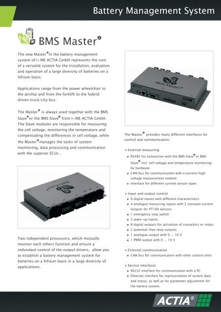
The new Master in the battery management<br />
system of I+<strong>ME</strong> <strong>ACTIA</strong> <strong>GmbH</strong> represents the core<br />
of a versatile system for the installation, evaluation<br />
and operation of a large diversity of batteries on a<br />
lithium basis.<br />
Applications range from the power wheelchair to<br />
the airship and from the forklift to the hybrid<br />
driven truck/city bus.<br />
<br />
The Master is always used together with the BMS<br />
c<br />
<br />
Slave or the BMS Slave from I+<strong>ME</strong> <strong>ACTIA</strong> <strong>GmbH</strong>.<br />
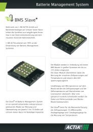
The Slave modules are responsible for measuring<br />
the cell voltage, monitoring the temperature and<br />
compensating the differences in cell voltage, while<br />
<br />
the Master manages the tasks of system<br />
monitoring, data processing and communication<br />
with the superior ECUs .<br />
<br />
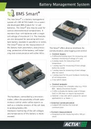
The Master provides many different interfaces for<br />
control and communication:<br />
External measuring<br />
RS485 for connection with the BMS Slave or BMS<br />
<br />
Slave incl. cell voltage and temperature monitoring<br />
by hardware<br />
CAN bus for communication with a current/high<br />
<br />
voltage measurement module<br />
Interface for different current sensor types<br />
<br />
c<br />
Two independent processors, which mutually<br />
monitor each others function and ensure a<br />
redundant control of the output drivers, allow you<br />
to establish a battery management system for<br />
batteries on a lithium basis in a large diversity of<br />
applications.<br />
Input and output control<br />
8 digital inputs with different characteristics<br />
<br />
4 analogue measuring inputs with 2 constant current<br />
<br />
outputs for PT100 sensors<br />
1 emergency stop switch<br />
<br />
2 wake-up inputs<br />
<br />
8 digital outputs for activation of contactors or relays<br />
<br />
2 potential-free relay outputs<br />
<br />
1 analogue output with 0 ... 10 V<br />
<br />
1 PWM output with 0 ... 10 V<br />
<br />
External communication<br />
CAN bus for communication with other control units<br />
<br />
Service interfaces<br />
RS232 interface for communication with a PC<br />
<br />
Ethernet interface for representation of system data<br />
<br />
and status, as well as for parameter adjustment for<br />
the battery system.
Technical data<br />
General Data Power supply voltage 12 / 24 VDC<br />
Environmental temperature – 20 °C … +70 °C<br />
Interfaces<br />
Outputs<br />
Inputs<br />
Wakeup<br />
Weight<br />
Dimensions<br />
RS485 interface<br />
1 kg<br />
approx. 150 x 230 x 40 mm incl. connector<br />
c <br />
for communikation with BMS Slave or Slave<br />
incl. input for hardware monitoring (voltage surge, over-temperature)<br />
3 x CAN interface for communication with other control systems or measurement modules<br />
Current sensor interface<br />
Ethernet<br />
RS232 interface<br />
LEDs<br />
for different types of current sensors<br />
with input for electric surge recognition<br />
for diagnosis & service<br />
for diagnosis & service<br />
BMS-Status<br />
8 x high-side switch, 2 x floating relay, 1 x analog,<br />
1 PWM, 2 x constant current for PT100 sensors<br />
for relays, fans and specific applications<br />
6 x voltage sensitive, 4 x analog input<br />
2 x current sensitive 1 of which is designed as security input<br />
1 x emergency stop input<br />
2 x wake-up input<br />
via CAN, 2 x digital input or time-controlled<br />
Possible battery system setup using BMS Master <br />
R<br />
+<br />
PlugIn<br />
IBAT<br />
measurement<br />
Load precharge<br />
R<br />
+<br />
Drive<br />
Slave controller<br />
? cell voltage control<br />
? temp. control<br />
? 2 nd level security<br />
Relay control Relay<br />
control<br />
BMS Master <br />
Relay control<br />
-<br />
Drive<br />
- PlugIn<br />
Contact<br />
I+<strong>ME</strong> <strong>ACTIA</strong> <strong>GmbH</strong><br />
Dresdenstr. 17/18<br />
D-38124 Braunschweig<br />
Tel.: + 49 (0) 531 38 701 0<br />
Fax: + 49 (0) 531 38 701 88<br />
info@ime-actia.de<br />
www.ime-actia.de<br />
All data included in this document is intended to be purely used as product information and does not represent or imply any liability with<br />
respect to accuracy and completeness of any data contained herein. Content is subject to technical modification without prior notice. All rights<br />
reserved © 2011 I+<strong>ME</strong> <strong>ACTIA</strong> <strong>GmbH</strong> IR12230C.