stand-alone renewable energy system based on hydrogen production
stand-alone renewable energy system based on hydrogen production
stand-alone renewable energy system based on hydrogen production

You also want an ePaper? Increase the reach of your titles
YUMPU automatically turns print PDFs into web optimized ePapers that Google loves.
STAND-ALONE RENEWABLE ENERGY SYSTEM<br />
BASED ON HYDROGEN PRODUCTION<br />
Tapan K. Bose, Kodjo Agbossou, Mohan Kolhe, Jean Hamelin<br />
Institut de recherche sur l’hydrogène, Université du Québec à Trois-Rivières, Canada<br />
1. PROJECT GOALS<br />
Energy storage can play an important role in the development and operati<strong>on</strong> of envir<strong>on</strong>mentally<br />
friendly <str<strong>on</strong>g>renewable</str<strong>on</strong>g> <str<strong>on</strong>g>energy</str<strong>on</strong>g> (RE) <str<strong>on</strong>g>system</str<strong>on</strong>g>s. The integrated wind and solar <str<strong>on</strong>g>energy</str<strong>on</strong>g> <str<strong>on</strong>g>system</str<strong>on</strong>g>, <str<strong>on</strong>g>based</str<strong>on</strong>g><br />
<strong>on</strong> l<strong>on</strong>g-term seas<strong>on</strong>al storage of electrolytic <strong>hydrogen</strong> (H 2 ), is c<strong>on</strong>sidered as a promising<br />
soluti<strong>on</strong> to overcome the limitati<strong>on</strong>s associated with the intermittency of the RE sources. In<br />
comparis<strong>on</strong> to comm<strong>on</strong>ly used battery storage, H 2 is well suited for seas<strong>on</strong>al storage, because<br />
of its inherent high mass <str<strong>on</strong>g>energy</str<strong>on</strong>g> density and l<strong>on</strong>gevity of <str<strong>on</strong>g>energy</str<strong>on</strong>g> storage (compared to<br />
batteries).<br />
A <str<strong>on</strong>g>stand</str<strong>on</strong>g>-<str<strong>on</strong>g>al<strong>on</strong>e</str<strong>on</strong>g> RE <str<strong>on</strong>g>system</str<strong>on</strong>g> <str<strong>on</strong>g>based</str<strong>on</strong>g> <strong>on</strong> <strong>hydrogen</strong> producti<strong>on</strong> from wind and solar <str<strong>on</strong>g>energy</str<strong>on</strong>g> has been<br />
developed and installed at the Hydrogen Research Institute (HRI). It includes a fuel cell and<br />
both short-term and l<strong>on</strong>g-term <str<strong>on</strong>g>energy</str<strong>on</strong>g> storage devices. It is the goal of this project to<br />
dem<strong>on</strong>strate that an aut<strong>on</strong>omous <str<strong>on</strong>g>renewable</str<strong>on</strong>g> <str<strong>on</strong>g>energy</str<strong>on</strong>g> <str<strong>on</strong>g>system</str<strong>on</strong>g> may be realized with l<strong>on</strong>g-term<br />
<str<strong>on</strong>g>energy</str<strong>on</strong>g> storage in the form of <strong>hydrogen</strong>, and that the operati<strong>on</strong> of such a <str<strong>on</strong>g>system</str<strong>on</strong>g> is safe and<br />
reliable. The major objectives are:<br />
• Assessment of the <strong>hydrogen</strong> producti<strong>on</strong> sub-assembly undergoing intermittent operati<strong>on</strong><br />
• Assessment of the fuel cell performance for matching residential electric and heat load<br />
profiles<br />
• Integrating the various sub-assemblies via hardware/software c<strong>on</strong>trol <str<strong>on</strong>g>system</str<strong>on</strong>g>s<br />
• Overall assessment of the technology for residential use in remote areas<br />
2. GENERAL DESCRIPTION OF PROJECT<br />
In order to dem<strong>on</strong>strate a variety of possible c<strong>on</strong>figurati<strong>on</strong>s, the RE <str<strong>on</strong>g>stand</str<strong>on</strong>g>-<str<strong>on</strong>g>al<strong>on</strong>e</str<strong>on</strong>g> <str<strong>on</strong>g>system</str<strong>on</strong>g> at HRI<br />
is operating with two different types of primary <str<strong>on</strong>g>renewable</str<strong>on</strong>g> <str<strong>on</strong>g>energy</str<strong>on</strong>g> sources. It includes a wind<br />
<str<strong>on</strong>g>energy</str<strong>on</strong>g> c<strong>on</strong>verter as well as a photovoltaic array. In additi<strong>on</strong>, as in any typical self-sufficient RE<br />
<str<strong>on</strong>g>system</str<strong>on</strong>g>, facilities for short-term and l<strong>on</strong>g-term <str<strong>on</strong>g>energy</str<strong>on</strong>g> storage must also be provided. A battery<br />
bank is used for short-term <str<strong>on</strong>g>energy</str<strong>on</strong>g> storage because it has a high charging-discharging<br />
efficiency and can be used to lessen the effects caused by instantaneous load ripples, spikes,<br />
electrolyser transients and wind <str<strong>on</strong>g>energy</str<strong>on</strong>g> peaks. However, batteries <str<strong>on</strong>g>al<strong>on</strong>e</str<strong>on</strong>g> are not appropriate for<br />
l<strong>on</strong>g-term storage because of their low <str<strong>on</strong>g>energy</str<strong>on</strong>g> density, self-discharge and leakage. The<br />
combinati<strong>on</strong> of a battery bank with l<strong>on</strong>g-term <str<strong>on</strong>g>energy</str<strong>on</strong>g> storage in the form of <strong>hydrogen</strong> can<br />
significantly improve the performance of <str<strong>on</strong>g>stand</str<strong>on</strong>g>-<str<strong>on</strong>g>al<strong>on</strong>e</str<strong>on</strong>g> RE <str<strong>on</strong>g>system</str<strong>on</strong>g>s. In such a RE <str<strong>on</strong>g>system</str<strong>on</strong>g>,<br />
electricity producti<strong>on</strong> in excess of demand is c<strong>on</strong>verted to <strong>hydrogen</strong>, using an electrolyser, and<br />
electricity requirement in excess of producti<strong>on</strong> is met by c<strong>on</strong>verting the stored <strong>hydrogen</strong> back to<br />
electricity using a fuel cell.<br />
- 1 -
The overall RE <str<strong>on</strong>g>system</str<strong>on</strong>g> performance is very sensitive to local weather c<strong>on</strong>diti<strong>on</strong>s. To achieve an<br />
adequate performance from such a <str<strong>on</strong>g>system</str<strong>on</strong>g> requires appropriate comp<strong>on</strong>ents and a welldesigned<br />
c<strong>on</strong>trol <str<strong>on</strong>g>system</str<strong>on</strong>g>. The design and implementati<strong>on</strong> of a c<strong>on</strong>trol <str<strong>on</strong>g>system</str<strong>on</strong>g> for proper <str<strong>on</strong>g>energy</str<strong>on</strong>g><br />
management in a <str<strong>on</strong>g>stand</str<strong>on</strong>g>-<str<strong>on</strong>g>al<strong>on</strong>e</str<strong>on</strong>g> RE plant is challenging. We have designed and developed a<br />
c<strong>on</strong>trol <str<strong>on</strong>g>system</str<strong>on</strong>g> with power c<strong>on</strong>diti<strong>on</strong>ing devices to integrate the different comp<strong>on</strong>ents of the RE<br />
<str<strong>on</strong>g>system</str<strong>on</strong>g> and to manage the <str<strong>on</strong>g>energy</str<strong>on</strong>g> flow in the <str<strong>on</strong>g>system</str<strong>on</strong>g> to assure a c<strong>on</strong>tinuous supply of electricity<br />
to meet the load demand. Each comp<strong>on</strong>ent of the <str<strong>on</strong>g>renewable</str<strong>on</strong>g> <str<strong>on</strong>g>energy</str<strong>on</strong>g> <str<strong>on</strong>g>system</str<strong>on</strong>g> has been studied<br />
for l<strong>on</strong>g-term operati<strong>on</strong> by using this c<strong>on</strong>trol algorithm. The <str<strong>on</strong>g>system</str<strong>on</strong>g> parameters are m<strong>on</strong>itored<br />
c<strong>on</strong>tinuously for real time operati<strong>on</strong> and c<strong>on</strong>trol. The <str<strong>on</strong>g>system</str<strong>on</strong>g> operati<strong>on</strong> has been tested for<br />
aut<strong>on</strong>omous operati<strong>on</strong> and technical feasibility of the <str<strong>on</strong>g>stand</str<strong>on</strong>g>-<str<strong>on</strong>g>al<strong>on</strong>e</str<strong>on</strong>g> RE <str<strong>on</strong>g>system</str<strong>on</strong>g> <str<strong>on</strong>g>based</str<strong>on</strong>g> <strong>on</strong><br />
<strong>hydrogen</strong> producti<strong>on</strong>. Our integrated RE <str<strong>on</strong>g>system</str<strong>on</strong>g> has been in operati<strong>on</strong> since May 2001.<br />
PLANT AT HYDROGEN RESEARCH INSTITUTE,<br />
UQTR, CANADA<br />
Electrical load<br />
Wind Turbine<br />
and<br />
Regulator<br />
PV Array<br />
and<br />
Regulator<br />
Inverter<br />
DC / AC<br />
BUS DC (Buffer with Batteries Bank)<br />
and POWER CONTROLLER<br />
Buck<br />
DC / DC<br />
C<strong>on</strong>verter<br />
Micro<br />
C<strong>on</strong>troller<br />
Micro<br />
C<strong>on</strong>troller<br />
Boost<br />
DC / DC<br />
C<strong>on</strong>verter<br />
Rectifier<br />
Master<br />
C<strong>on</strong>troller<br />
Compressor<br />
PEMFC<br />
Hydrogen Powered Generator<br />
Electrolyzer<br />
H 2 Tank<br />
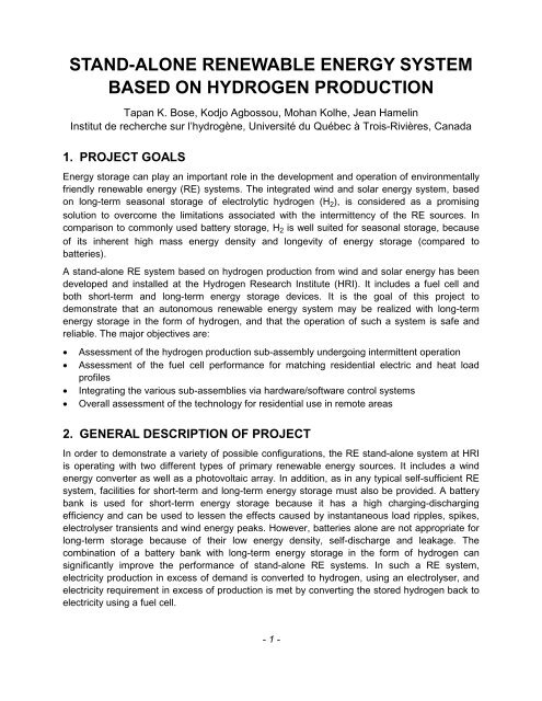
Figure 1: Stand-<str<strong>on</strong>g>al<strong>on</strong>e</str<strong>on</strong>g> Renewable Energy System at the Hydrogen Research Institute<br />
3. DESCRIPTION OF COMPONENTS<br />
The <str<strong>on</strong>g>stand</str<strong>on</strong>g>-<str<strong>on</strong>g>al<strong>on</strong>e</str<strong>on</strong>g> RE <str<strong>on</strong>g>system</str<strong>on</strong>g> <str<strong>on</strong>g>based</str<strong>on</strong>g> <strong>on</strong> <strong>hydrogen</strong> producti<strong>on</strong> was successfully tested at the HRI.<br />
The <str<strong>on</strong>g>system</str<strong>on</strong>g> c<strong>on</strong>sists of a 10 kW wind turbine generator (WTG) and a 1 kW (peak) solar<br />
photovoltaic (PV) array as primary <str<strong>on</strong>g>energy</str<strong>on</strong>g> sources. The <str<strong>on</strong>g>renewable</str<strong>on</strong>g> electricity that is produced in<br />
excess of the load demand is stored as <strong>hydrogen</strong>, produced using a 5 kW electrolyser. The<br />
<strong>hydrogen</strong> is stored and later used to produce electricity using a 5 kW fuel cell <str<strong>on</strong>g>system</str<strong>on</strong>g> for the<br />
times when there is not sufficient wind and solar <str<strong>on</strong>g>energy</str<strong>on</strong>g> to meet the demand requirement. The<br />
- 2 -
RE <str<strong>on</strong>g>system</str<strong>on</strong>g> comp<strong>on</strong>ents have substantially different voltage-current characteristics and are<br />
integrated through the developed power c<strong>on</strong>diti<strong>on</strong>ing devices <strong>on</strong> a 48V DC bus, which allows<br />
power to be managed between input power, <str<strong>on</strong>g>energy</str<strong>on</strong>g> storage and load. The DC-DC c<strong>on</strong>verters<br />
are used as power c<strong>on</strong>diti<strong>on</strong>ing devices to c<strong>on</strong>nect the fuel cell and the electrolyser <strong>on</strong> the DC<br />
bus, which have different voltage ratings. Also the DC-DC c<strong>on</strong>verters give high flexibility to<br />
c<strong>on</strong>trol power flow and operati<strong>on</strong> of the electrolyser and the fuel cell. Compared to the DC bus<br />
voltage, the fuel cell output voltage is low and hence the DC-DC boost c<strong>on</strong>verter is used to<br />
transfer the power effectively to the DC bus. Similarly, the DC-DC buck c<strong>on</strong>verter has been<br />
used between the electrolyser and the DC bus to transfer the excess power effectively to the<br />
electrolyser. In additi<strong>on</strong>, the <str<strong>on</strong>g>system</str<strong>on</strong>g> is equipped with AC and DC programmable loads and with<br />
a 10 kW programmable power source. The schematic of the RE <str<strong>on</strong>g>system</str<strong>on</strong>g> is shown in Figure 1<br />
and the <str<strong>on</strong>g>system</str<strong>on</strong>g> comp<strong>on</strong>ents’ specificati<strong>on</strong>s are given in Table 1.<br />
Table 1: Specificati<strong>on</strong>s of the <str<strong>on</strong>g>renewable</str<strong>on</strong>g> <str<strong>on</strong>g>energy</str<strong>on</strong>g> <str<strong>on</strong>g>system</str<strong>on</strong>g> comp<strong>on</strong>ents<br />
Comp<strong>on</strong>ent<br />
Wind Turbine Generator<br />
Photovoltaic Array<br />
Electrolyser<br />
Buck C<strong>on</strong>verter<br />
Fuel Cell System<br />
Boost C<strong>on</strong>verter<br />
C<strong>on</strong>troller<br />
DC Load<br />
AC Load<br />
Inverter<br />
Battery<br />
Power Source<br />
H2 Storage<br />
Specificati<strong>on</strong>s<br />
10 kW, 3φ permanent magnet alternator, VCS-10 - 48 V DC,<br />
Bergey– BWC Excel<br />
1 kW (peak) PV array, Golden Genesis GP 64 PV Modules (4S*4P)<br />
with Charge C<strong>on</strong>troller<br />
5 kW, alkaline electrolyser with compressor, Stuart Energy System<br />
5 kW, multiphase PWM, 36-48 Volt, HRI System<br />
5 kW, prot<strong>on</strong> exchange membrane fuel cell stack (MK5-E), 19-35 Volt,<br />
Ballard Power System<br />
5 kW, multiphase PWM, 24-48 Volt, HRI System<br />
<str<strong>on</strong>g>energy</str<strong>on</strong>g> management c<strong>on</strong>trol <str<strong>on</strong>g>system</str<strong>on</strong>g>, HRI System<br />
12 kW (programmable), water cooled, Dynaload<br />
3 kW (programmable), California Instruments<br />
5 kW, Trace Engineering<br />
42.240 kWh<br />
10 kW (programmable), Elgar<br />
10 bar, 3.8 m 3 represents 125 kWh of stored <str<strong>on</strong>g>energy</str<strong>on</strong>g><br />
Current from the DC bus bar keeps batteries (short-term <str<strong>on</strong>g>energy</str<strong>on</strong>g> storage) charged, feeds power<br />
to the load bank via an inverter and also supplies power to electrolyser via the powerc<strong>on</strong>diti<strong>on</strong>ing<br />
device. To simulate any type of electrical load profile, we used DC and AC<br />
programmable loads. Our RE <str<strong>on</strong>g>system</str<strong>on</strong>g> also has a programmable power source at DC bus and<br />
can be used to test the <str<strong>on</strong>g>system</str<strong>on</strong>g>, when there is no power available from wind and solar <str<strong>on</strong>g>energy</str<strong>on</strong>g><br />
<str<strong>on</strong>g>system</str<strong>on</strong>g>. The programmable power source can simulate any type of intermittent power output.<br />
- 3 -
We studied the electrolyser and the fuel cell polarizati<strong>on</strong> characteristics, which depend mainly<br />
<strong>on</strong> voltage, current and temperature. Sensors were used to record real-time voltages and<br />
currents of WTG, PV array, DC bus / battery, electrolyser, fuel cell, load, <strong>hydrogen</strong> detectors,<br />
electrolytic <strong>hydrogen</strong> flow rate from the electrolyser, <strong>hydrogen</strong> c<strong>on</strong>sumpti<strong>on</strong> rate in the fuel cell,<br />
oxidant c<strong>on</strong>sumpti<strong>on</strong> rate in the fuel cell, <strong>hydrogen</strong> and oxidant pressure in the fuel cell, fuel cell<br />
stack temperature, electrolyser cell temperature, DC-DC c<strong>on</strong>verter (boost and buck) duty ratio.<br />
Additi<strong>on</strong>al sensors in the electrolyser and the fuel cell <str<strong>on</strong>g>system</str<strong>on</strong>g>s provide the sec<strong>on</strong>dary<br />
informati<strong>on</strong>.<br />
4. RENEWABLE ENERGY SYSTEM OPERATION AND CONTROL<br />
A c<strong>on</strong>trol <str<strong>on</strong>g>system</str<strong>on</strong>g> is required for efficient <str<strong>on</strong>g>energy</str<strong>on</strong>g> management and aut<strong>on</strong>omous operati<strong>on</strong> of the<br />
RE plant. The c<strong>on</strong>trol <str<strong>on</strong>g>system</str<strong>on</strong>g> is a challenge because the sensor data required for c<strong>on</strong>tinuous<br />
real-time operati<strong>on</strong> are fed to the same c<strong>on</strong>trol algorithm that is used to send signals to the<br />
power c<strong>on</strong>diti<strong>on</strong>ing devices <strong>on</strong> a real-time basis. The c<strong>on</strong>trol <str<strong>on</strong>g>system</str<strong>on</strong>g> was developed to c<strong>on</strong>trol<br />
the aut<strong>on</strong>omous operati<strong>on</strong>, even with intermittent RE sources. It was designed to maximize the<br />
direct <str<strong>on</strong>g>energy</str<strong>on</strong>g> flow from the RE sources to the electrolyser and the load in order to avoid losses<br />
in the batteries. The <str<strong>on</strong>g>energy</str<strong>on</strong>g> level at the DC bus plays an important role for the operati<strong>on</strong> and<br />
c<strong>on</strong>trol of the RE plant. It allows effective <str<strong>on</strong>g>energy</str<strong>on</strong>g> management am<strong>on</strong>g the primary power<br />
sources, the electrolyser input, the fuel cell output and the load. The c<strong>on</strong>trol <str<strong>on</strong>g>system</str<strong>on</strong>g> c<strong>on</strong>sists of<br />
a master c<strong>on</strong>troller and two sec<strong>on</strong>dary micro c<strong>on</strong>trollers (Figure 1). The real-time data of RE<br />
<str<strong>on</strong>g>system</str<strong>on</strong>g> are recorded and used for decisi<strong>on</strong>-making in the c<strong>on</strong>trol algorithm. With respect to<br />
<str<strong>on</strong>g>energy</str<strong>on</strong>g> level at DC bus and pre-defined limits of <str<strong>on</strong>g>energy</str<strong>on</strong>g> levels in the c<strong>on</strong>trol algorithm, the<br />
master c<strong>on</strong>troller sends the c<strong>on</strong>diti<strong>on</strong>ed signal (duty ratio) to the sec<strong>on</strong>dary c<strong>on</strong>trollers for <strong>on</strong> /<br />
off operati<strong>on</strong> of the electrolyser and the fuel cell. The sec<strong>on</strong>dary micro c<strong>on</strong>trollers manage the<br />
power flow with respect to the <str<strong>on</strong>g>energy</str<strong>on</strong>g> availability at DC bus through the digitally c<strong>on</strong>trolled DC-<br />
DC c<strong>on</strong>verters. The DC-DC c<strong>on</strong>verters use multiphase technique to generate pulse width<br />
modulati<strong>on</strong> signals to c<strong>on</strong>trol the power flow. The limits of <str<strong>on</strong>g>energy</str<strong>on</strong>g> levels in the c<strong>on</strong>trol algorithm<br />
are managed through double hysteresis strategy. The DC-DC (i.e. buck and boost) c<strong>on</strong>verters<br />
are important comp<strong>on</strong>ents in the <str<strong>on</strong>g>system</str<strong>on</strong>g> for effective operati<strong>on</strong> and power flow c<strong>on</strong>trol of the<br />
electrolyser and the fuel cell. The c<strong>on</strong>trol algorithm was developed in such a way that the fuel<br />
cell and the electrolyser do not operate simultaneously. The limits of <str<strong>on</strong>g>energy</str<strong>on</strong>g> level in the c<strong>on</strong>trol<br />
algorithm and the load profile were varied from time to time to check the reliability and the<br />
technical feasibility of the c<strong>on</strong>trol <str<strong>on</strong>g>system</str<strong>on</strong>g> for aut<strong>on</strong>omous operati<strong>on</strong>. Although the major power<br />
comp<strong>on</strong>ents in the <str<strong>on</strong>g>system</str<strong>on</strong>g> are intermittent in nature, the integrated RE <str<strong>on</strong>g>system</str<strong>on</strong>g> has operated<br />
automatically and effectively by using the c<strong>on</strong>trol algorithm and power c<strong>on</strong>diti<strong>on</strong>ing devices.<br />
The excess <str<strong>on</strong>g>energy</str<strong>on</strong>g> is stored as <strong>hydrogen</strong>, which is produced electrolytically using the <strong>hydrogen</strong><br />
producti<strong>on</strong> <str<strong>on</strong>g>system</str<strong>on</strong>g>, c<strong>on</strong>sists of a 5 kW electrolyser with a c<strong>on</strong>trol unit, a compressor, purificati<strong>on</strong><br />
and drying process. The electrolyser input <str<strong>on</strong>g>energy</str<strong>on</strong>g> is c<strong>on</strong>trolled, with respect to <str<strong>on</strong>g>energy</str<strong>on</strong>g> available<br />
at DC bus, through the duty ratio of DC-DC c<strong>on</strong>verter. The H 2 produced by the electrolyser is<br />
temporarily stored in a water-sealed tank of the electrolyser <str<strong>on</strong>g>system</str<strong>on</strong>g> and when this tank is full,<br />
the electrolyser compressor starts automatically and sends the <strong>hydrogen</strong>, at high pressure,<br />
through the purificati<strong>on</strong> and drying process and to the main storage tank of 3.8 m 3 capacity. The<br />
time cycle period, which corresp<strong>on</strong>ds to the filling and compressi<strong>on</strong> of the <strong>hydrogen</strong> in the<br />
water-sealed tank, depends <strong>on</strong> the electrolyser input power. The stored <strong>hydrogen</strong> is utilized to<br />
produce electrical <str<strong>on</strong>g>energy</str<strong>on</strong>g> <str<strong>on</strong>g>based</str<strong>on</strong>g> <strong>on</strong> the load requirement through a 5 kW fuel cell. The fuel cell<br />
power output is managed <str<strong>on</strong>g>based</str<strong>on</strong>g> <strong>on</strong> the <str<strong>on</strong>g>energy</str<strong>on</strong>g> requirement via the DC-DC c<strong>on</strong>verter. The<br />
- 4 -
electrolyser and fuel cell <strong>on</strong> / off operati<strong>on</strong>s are c<strong>on</strong>trolled automatically as a functi<strong>on</strong> of predefined<br />
limits of <str<strong>on</strong>g>energy</str<strong>on</strong>g> levels in the c<strong>on</strong>trol algorithm.<br />
5. RENEWABLE ENERGY SYSTEM PERFORMANCE<br />
The performance of RE <str<strong>on</strong>g>system</str<strong>on</strong>g> is shown in Figures 2 through 7 for a typical day and for l<strong>on</strong>gterm<br />
operati<strong>on</strong>. The <str<strong>on</strong>g>energy</str<strong>on</strong>g> available from the WTG and the PV array for a typical day (in this<br />
case, 10 December 2001) is shown in Figure 2. On this day of operati<strong>on</strong>, the c<strong>on</strong>trol algorithm<br />
was set to start the electrolyser at 99% of <str<strong>on</strong>g>energy</str<strong>on</strong>g> level at DC bus and to stop the electrolyser at<br />
84%. The fuel cell <strong>on</strong> and off set points were 83% and 85%, respectively. During this operati<strong>on</strong>,<br />
the RE source power, the load profile, the electrolyser input power, the <strong>hydrogen</strong> flow rate, the<br />
fuel cell output power, and the <strong>hydrogen</strong> c<strong>on</strong>sumpti<strong>on</strong> rate were recorded and are shown in<br />
Figure 3. The ripples and peaks in the electrolyser power are due to the cyclic operati<strong>on</strong> of the<br />
compressor. The <strong>hydrogen</strong> flow rate is measured as it is sent to the main storage tank. The<br />
power flow of batteries (i.e. charging / discharging) is also carefully m<strong>on</strong>itored. The power<br />
supplied to the electrolyser is mainly from the short-term <str<strong>on</strong>g>energy</str<strong>on</strong>g> storage (i.e. batteries) when<br />
insufficient <str<strong>on</strong>g>energy</str<strong>on</strong>g> was available from the RE sources. The electrolyser and the fuel cell were<br />
started and stopped automatically as per pre-defined <str<strong>on</strong>g>energy</str<strong>on</strong>g> levels in the c<strong>on</strong>trol algorithm. In<br />
the c<strong>on</strong>trol algorithm, the proper selecti<strong>on</strong> of <str<strong>on</strong>g>energy</str<strong>on</strong>g> levels is required for the most effective<br />
operati<strong>on</strong> of the electrolyser and the fuel cell. However, the choice is a complicated problem and<br />
was determined <strong>on</strong>ly by trial and error. The <str<strong>on</strong>g>energy</str<strong>on</strong>g> levels are chosen in such a way so as to<br />
keep the batteries at a near-full charge, <strong>on</strong>ly allowing them to be discharged for a short period<br />
and then recharged. This allows the batteries to act as a buffer for the RE <str<strong>on</strong>g>system</str<strong>on</strong>g>, when<br />
comp<strong>on</strong>ents such as electrolyser or load bank are suddenly turned <strong>on</strong>. The performance of the<br />
electrolyser and fuel cell were judged by different efficiencies. The electrolyser utilizati<strong>on</strong> factor<br />
(i.e. current efficiency) was about 85%; the <str<strong>on</strong>g>energy</str<strong>on</strong>g> efficiency with the compressor running was<br />
about 60% and without the compressor running it was 65%. The fuel cell utilizati<strong>on</strong> factor was<br />
about 90% and the <str<strong>on</strong>g>energy</str<strong>on</strong>g> efficiency was more than 45%.<br />
The RE <str<strong>on</strong>g>system</str<strong>on</strong>g> performance was recorded for l<strong>on</strong>g-term operati<strong>on</strong> from 3 December 2001 to 17<br />
April 2002 for daily operati<strong>on</strong> of six hours. Frequently, no <str<strong>on</strong>g>energy</str<strong>on</strong>g> was available from the RE<br />
sources at our locati<strong>on</strong> because of climatic c<strong>on</strong>diti<strong>on</strong>s. Therefore, a 10 kW programmable power<br />
source was used to simulate the typical RE patterns for those days when no RE power was<br />
available. During this period, the power available from primary <str<strong>on</strong>g>energy</str<strong>on</strong>g> sources is shown in<br />
Figure 4. The electrolyser input power, the fuel cell output power, the batteries charging /<br />
discharging power at the DC bus, and the load profile are shown in Figures 5 and 6. The<br />
electrolyser input <str<strong>on</strong>g>energy</str<strong>on</strong>g> and the corresp<strong>on</strong>ding <strong>hydrogen</strong> flow rate are shown in Figure 7. The<br />
electrolyser, the fuel cell operati<strong>on</strong> and power flow were automatically managed through the<br />
digitally c<strong>on</strong>trolled DC-DC c<strong>on</strong>verters. The master c<strong>on</strong>troller used informati<strong>on</strong> obtained through<br />
the sensors to make the required decisi<strong>on</strong>s and c<strong>on</strong>trol the entire operati<strong>on</strong>. The load profile,<br />
the programmed output <str<strong>on</strong>g>energy</str<strong>on</strong>g> pattern of the DC power source and the <str<strong>on</strong>g>energy</str<strong>on</strong>g> levels in the<br />
c<strong>on</strong>trol algorithm were changed from time to time to check the reliability of the <str<strong>on</strong>g>system</str<strong>on</strong>g> and the<br />
validity of the developed c<strong>on</strong>trol algorithm. The performance analysis shows that an<br />
aut<strong>on</strong>omous RE <str<strong>on</strong>g>system</str<strong>on</strong>g> <str<strong>on</strong>g>based</str<strong>on</strong>g> <strong>on</strong> electrolytic <strong>hydrogen</strong> is safe and reliable.<br />
- 5 -
Figure 2: Power available from wind turbine generator and PV array <strong>on</strong> Dec 10, 2001<br />
Figure 3: Power, H 2 flow rate and c<strong>on</strong>sumpti<strong>on</strong> rate in RE <str<strong>on</strong>g>system</str<strong>on</strong>g> <strong>on</strong> Dec 10, 2001<br />
- 6 -
5000<br />
4000<br />
Power from Primary Sources (W)<br />
3000<br />
2000<br />
1000<br />
0<br />
0 2 3 4 6 7 8 9 12 13 14 15 16 17 18 19 21 23 24 26 28<br />
Time (day of operati<strong>on</strong>)<br />
Figure 4: Power available from primary <str<strong>on</strong>g>energy</str<strong>on</strong>g> sources<br />
.<br />
6000<br />
5000<br />
Electrolyser Input Power<br />
FC Power<br />
4000<br />
Power (W)<br />
3000<br />
2000<br />
1000<br />
0<br />
0 2 3 4 6 7 8 9 12 13 14 15 16 17 18 19 21 23 24 26 28<br />
Time (day of operati<strong>on</strong>)<br />
(a)<br />
Figure 5: Electrolyser input and fuel cell output<br />
- 7 -
5000<br />
5000<br />
Battery Charging / Discharging Power<br />
Load<br />
Battery Charging / Discharging Power (W)<br />
3000<br />
1000<br />
-1000<br />
-3000<br />
4000<br />
3000<br />
2000<br />
1000<br />
Load (W)<br />
-5000<br />
0<br />
0 2 3 4 6 7 8 9 12 13 14 15 16 17 18 19 21 23 24 26 28<br />
Time (day of operati<strong>on</strong>)<br />
(b)<br />
Figure 6: Battery charging /discharging and load power<br />
6000<br />
Electrolyser Input Power<br />
H2 Flow Rate<br />
90<br />
Power (W)<br />
4000<br />
2000<br />
60<br />
30<br />
H2 Flow Rate (Lit/min)<br />
0<br />
0<br />
0 2 3 4 6 7 8 9 12 13 14 15 16 17 18 19 21 23 24 26 28<br />
Time (day of operati<strong>on</strong>)<br />
Figure 7: Electrolyser input power and H 2 flow rate<br />
- 8 -
6. CONCLUSIONS<br />
The successful l<strong>on</strong>g-term aut<strong>on</strong>omous operati<strong>on</strong> and performance of a <str<strong>on</strong>g>stand</str<strong>on</strong>g>-<str<strong>on</strong>g>al<strong>on</strong>e</str<strong>on</strong>g> RE <str<strong>on</strong>g>system</str<strong>on</strong>g><br />
<str<strong>on</strong>g>based</str<strong>on</strong>g> <strong>on</strong> <strong>hydrogen</strong> producti<strong>on</strong> has been dem<strong>on</strong>strated using a c<strong>on</strong>trol <str<strong>on</strong>g>system</str<strong>on</strong>g> and power<br />
c<strong>on</strong>diti<strong>on</strong>ing devices. The comp<strong>on</strong>ents of the RE <str<strong>on</strong>g>system</str<strong>on</strong>g>, which have substantially different<br />
voltage-current characteristics, were integrated using power c<strong>on</strong>diti<strong>on</strong>ing devices <strong>on</strong> the DC bus<br />
for effective operati<strong>on</strong>. The <str<strong>on</strong>g>system</str<strong>on</strong>g> was tested successfully for aut<strong>on</strong>omous operati<strong>on</strong>. The<br />
sensors collected real-time data and utilized this informati<strong>on</strong> in the c<strong>on</strong>trol algorithm for effective<br />
<str<strong>on</strong>g>energy</str<strong>on</strong>g> management in the <str<strong>on</strong>g>system</str<strong>on</strong>g>. The buffer <str<strong>on</strong>g>energy</str<strong>on</strong>g> storage provided by batteries managed<br />
the load transients, electrolyser ripples and the intermittent power peaks from the RE sources<br />
efficiently. The developed c<strong>on</strong>trol <str<strong>on</strong>g>system</str<strong>on</strong>g> and power c<strong>on</strong>diti<strong>on</strong>ing devices were tested for<br />
different load profiles and for various intermittent input power patterns, which were also<br />
generated through the programmable DC power source.<br />
We also used a programmable power source as input to our RE <str<strong>on</strong>g>system</str<strong>on</strong>g>, which can simulate any<br />
type of intermittent power output by using the wind or solar <str<strong>on</strong>g>energy</str<strong>on</strong>g> profile of any regi<strong>on</strong>. The<br />
different load profiles were generated using a programmable load to test the <str<strong>on</strong>g>system</str<strong>on</strong>g> operati<strong>on</strong><br />
and performance. The <str<strong>on</strong>g>stand</str<strong>on</strong>g>-<str<strong>on</strong>g>al<strong>on</strong>e</str<strong>on</strong>g> RE <str<strong>on</strong>g>system</str<strong>on</strong>g> developed at the HRI can thus be utilized to test<br />
the operati<strong>on</strong> and performance of any <str<strong>on</strong>g>stand</str<strong>on</strong>g>-<str<strong>on</strong>g>al<strong>on</strong>e</str<strong>on</strong>g> RE <str<strong>on</strong>g>system</str<strong>on</strong>g> <str<strong>on</strong>g>based</str<strong>on</strong>g> <strong>on</strong> electrolytic <strong>hydrogen</strong>.<br />
Acknowledgement:<br />
This work was supported in part by the Ministère des ressources Naturelles du Québec, Natural<br />
Resources Canada, Natural Sciences and Engineering Research Council of Canada, Canada<br />
Foundati<strong>on</strong> of Innovati<strong>on</strong>, the AUTO21 Centre of Excellence. We would like to thank Ballard<br />
Power for the fuel cell <str<strong>on</strong>g>system</str<strong>on</strong>g> and Stuart Energy Inc. for the electrolyser.<br />
7. CONTACT INFORMATION<br />
Institut de recherche sur l’hydrogène / Hydrogen Research Institute<br />
Tapan K. Bose, director<br />
Université du Québec à Trois-Rivières<br />
C.P. 500<br />
Trois-Rivières, Québec, G9A 5H7, Canada<br />
Teleph<strong>on</strong>e: 001 819 376-5139<br />
Fax: 001 819 376-5164<br />
E-mail: Tapan_Bose@uqtr.ca<br />
- 9 -