Grimstad Renewable Energy Park - Hydrogen Implementing ...
Grimstad Renewable Energy Park - Hydrogen Implementing ...
Grimstad Renewable Energy Park - Hydrogen Implementing ...

You also want an ePaper? Increase the reach of your titles
YUMPU automatically turns print PDFs into web optimized ePapers that Google loves.
GRIMSTAD RENEWABLE ENERGY PARK<br />
Torstein Våland, Willy Bartholdsen, Morten Ottestad, Magne Våge<br />
Agder University College, NO-4878 <strong>Grimstad</strong>, Norway<br />
1. PROJECT GOALS AND TECHNICAL OBJECTIVES<br />
1.1 Norwegian National Centre for renewable energy<br />
On May 23, 1997, Agder University College (HiA), Aust-Agder Kraftverk (AAK), and Vest-Agder<br />
Energiverk (VAE) signed an agreement to cooperatively develop renewable energy and energy<br />
efficient technologies. Kristiansand Energiverk joined the partnership in 1998. In 2001, the three<br />
energy companies joined to form one company, called Agder Energi (AE), and became one of<br />
the major energy companies in Norway. The intention of the partnership agreement was to<br />
improve the competence of the partners in renewable energy technologies other than hydroelectricity,<br />
which has been their main focus up to now. Four areas were defined as important:<br />
• International contacts<br />
• Ph.D. program<br />
• <strong>Energy</strong> studies<br />
• <strong>Energy</strong> <strong>Park</strong><br />
The success of the international hydrogen conference, HYPOTHESIS II, held in <strong>Grimstad</strong> in<br />
August 1997, provided the basis for an international network. The previous year, the Norsk<br />
<strong>Hydrogen</strong> Forum (NHF), a forum for Norwegian institutions and companies interested in<br />
hydrogen technologies, was established. The college, HiA, is hosting the secretariat for NHF.<br />
The Ph.D. program began in 1999. It is financed by two companies, AE and ELKEM, a major<br />
Norwegian company that produces silicon, and the Norwegian Research Council (NFR). Five<br />
Ph.D. students are now working in the program. A new Ph.D. student, financed by the Minister<br />
of Education and Research, will soon join the programme. The areas studied are hydrogen,<br />
solar grade silicon materials, wind energy, and economics related to renewable energy. Two<br />
engineering courses related to renewable energy have been established, one in technical<br />
economics, with a focus on renewable energy and one in electrical engineering, with focus on<br />
renewable energy.<br />
Efforts regarding the last item, the <strong>Energy</strong> <strong>Park</strong>, are the focus of this paper.<br />
1.2 The <strong>Energy</strong> <strong>Park</strong><br />
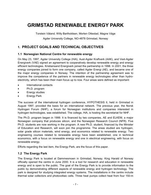
The <strong>Energy</strong> <strong>Park</strong> is located at Dømmesmoen in <strong>Grimstad</strong>, Norway. King Harald of Norway<br />
officially opened the centre in June 2000. It is a tool for research and education in renewable<br />
energy and is open to the public. The goal of the <strong>Energy</strong> <strong>Park</strong> is to provide information to the<br />
public by demonstrating different aspects of renewable energy and hydrogen technology. The<br />
park is designed for studying integrated energy systems. The installations in the centre include<br />
thermal solar collectors and photovoltaic cells. Three heat pumps collect heat from four 150-m<br />
- 1 -
deep boreholes, which are also connected to the solar collectors. An electrolyser, which<br />
produces hydrogen, and hydrogen storage tanks are also installed at the site. Recently, a 2.5kW<br />
alkaline fuel cell stack has been obtained for the centre. All subsystems, such as the<br />
electrolyte circulation system, CO2 removal system, fans, etc. are implemented. However, there<br />
is still work to be done on the control system. The total fuel cell system will be started and<br />
tested in December 2002.<br />
Recently, energy crops, i.e., Reed Canary Grass, Elephant Grass, and Short rotation coppice of<br />
willow, have been planted at the <strong>Energy</strong> <strong>Park</strong>. The aim is to study the energy content of these<br />
plants under Norwegian conditions.<br />
Figure 1: An overview over the <strong>Energy</strong> <strong>Park</strong> at Dømmesmoen, <strong>Grimstad</strong><br />
2. GENERAL DESCRIPTION<br />
The <strong>Energy</strong> <strong>Park</strong> is financed by the Norwegian Water Resources and <strong>Energy</strong> Directorate, the<br />
<strong>Energy</strong> Efficiency Centres of Agder, Agder <strong>Energy</strong>, Norsk Hydro Electrolysers, and HiA. It is<br />
located in <strong>Grimstad</strong> (in Southern Norway) at Dømmesmoen, a former horticultural school, which<br />
is now part of HiA. An overhead photograph and a schematic drawing of the <strong>Energy</strong> <strong>Park</strong> are<br />
shown in Figures 1 and 2, respectively. As can be seen, the park has two lines, one thermal line<br />
and one electric line.<br />
The thermal line consists of 85 m 2 solar collectors, heat exchangers, three heat pumps, and<br />
water heat storage tanks. Four 150-m deep boreholes can be used for heat collection as well as<br />
for heat storage. The heat pumps and solar collectors can be combined for optimum operation.<br />
The thermal energy is used to heat a nearby building.<br />
- 2 -
Figure 2: A schematic drawing of the <strong>Energy</strong> <strong>Park</strong><br />
The electric line, which consists of 220 m 2 PV cells and inverters, produces 400 V AC (50 Hz).<br />
The electricity can be fed into the main grid or used to power a 50-kW high-pressure<br />
electrolyser to produce hydrogen. The hydrogen is stored in two storage tanks until it is used to<br />
power fuel cells and other hydrogen-fueled equipment, such as small gas turbines. The<br />
instrumentation and equipment are housed in three separate locations, mainly for safety<br />
reasons.<br />
Because the wind in the <strong>Grimstad</strong> area is quite calm, there are no wind turbines in the energy<br />
park. However, AE is owner of a windmill park at Lindesnes, the most southern part of Norway.<br />
A direct data transfer line between the windmill park and the energy park will be established in<br />
order to enable wind energy studies at Dømmesmoen.<br />
3. DESCRIPTION OF THE COMPONENTS<br />
3.1 The thermal system<br />
The solar collector systems are standing free on the ground (see Figure 1). Four types of solar<br />
collectors are installed:<br />
• 22.5 m 2 of Viessmann w 2.5 solar collectors are divided into 3 groups, connected in parallel<br />
• 25 m 2 of Arcon HT collectors are divided into 2 groups, connected in series<br />
• 28 m 2 of Solsam LGB1 collectors are divided into 2 groups, connected in parallel.<br />
- 3 -
Figure 3: Heat production from Viessman solar collectors<br />
Figure 4: Heat production from Arcon solar collectors<br />
- 4 -
Figure 5: Heat production from Solsam solar collectors<br />
The thermal energy produced by each of the systems is shown in Figures 3-5. The<br />
measurements were made on August 8, 2002. The heat production was calculated by<br />
measuring the temperature difference between the output and input temperature on the<br />
collector and the temperature of the fluid flowing through the collectors, using the heat capacity<br />
of the solution.<br />
The global radiation is also presented in Figures 3-5. As the figures show, the heat production<br />
from the solar collectors closely follows the global radiation curve. Viessman and Solsam have<br />
both a maximum production close to 500 W/m 2 , while Arcon has a maximum close to<br />
600 W/m 2 .<br />
Plate heat exchangers are used to transfer the heat between the collectors and the heat<br />
storage systems (primary and secondary systems). The heating fluid flowing through the solar<br />
collectors is a glycol-water mixture and water is used for the storage tank. Figure 6 shows the<br />
piping and the storage tanks inside the thermal cottage.<br />
In addition to the three systems mentioned above, a small system, designed for use in small<br />
houses, provides heat for one of the cottages. This system consists of two groups of Solsam<br />
vacuum solar collectors mounted on the roof of the thermal cottage (see Figure 7). The system<br />
has a total area of 6.6 m 2 . It can be connected either in series or in parallel. The temperature is<br />
controlled by a standard residential thermostat.<br />
- 5 -
Figure 6: A view of the storage tank and the piping inside the thermal cottage<br />
In addition to the solar collectors, four boreholes are drilled in the ground. They are 150-m deep<br />
with a diameter of 15 cm. In two of the wells, the ground water is flowing freely. The other two<br />
are nearly dry. This gives us an opportunity to extract heat from the ground water and to store<br />
heat in the two dry wells. The heat is extracted by means of heat pumps. Three heat pumps are<br />
available:<br />
• House pack 9Z - nominal output heat 30 kW<br />
• BVNor BV-60vv - nominal output heat 7 kW<br />
• Mec 6TB - nominal output heat 6 kW<br />
A pipeline is used to transfer heat from this location to the nearby buildings, over a distance of<br />
230 m.<br />
- 6 -
3.2 The electric system<br />
Two types of photovoltaic cells are installed:<br />
Figure 7: Solar collectors on the roof<br />
• Unisolar US64, triple junction amorphous cells - total area 150 m 2 . They are divided into five<br />
different circuits. Each circuit has four groups connected in parallel and each group consists<br />
of eight panels connected in series. The nominal power is 64 W/m 2 .<br />
• Neste NP100G, polycrystalline cells - total area 72 m 2 . The cells are divided into four<br />
different circuits. Each circuit has two groups connected in parallel. Each group has 12<br />
panels connected in series. The nominal power is 119 W/m 2 .<br />
The total nominal power is 20 kW DC. Because AC is often needed, four 2-kW Sunny Boy SWR<br />
2000 inverters are installed. They convert DC power to 400 V AC/50 Hz.<br />
The flexible design of the system makes it possible to perform several different experiments<br />
and also allows power to be fed to the main grid.<br />
- 7 -
3.3 <strong>Hydrogen</strong> related components<br />
3.3.1 Electrolyser<br />
A 50-kW high-pressure electrolyser (Norsk Hydro Electrolysers HPE 10) is installed in the park<br />
(see Figure 8). It is an alkaline electrolyser producing hydrogen at 15 bars. The maximum<br />
hydrogen production rate is 10 Nm 3 per hour with a purity of 99.9%. The hydrogen is stored at a<br />
pressure of 15 bars in one of two hydrogen storage tanks. Each hydrogen storage tank has a<br />
volume of 4 m 3 . Currently the oxygen produced is vented to the air.<br />
3.3.2 Fuel cells<br />
Figure 8: The 50 kW high-pressure alkaline electrolyser<br />
A 2.5-kW alkaline fuel cell stack has been obtained from Ze-Tek Power. It will be installed in the<br />
park in the near future. In addition to the stack, subsystems required for fuel cell operation<br />
include systems for electrolyte circulation, CO 2 removal, cooling, air fans, and control. All of the<br />
subsystems, except the control system, are now finished. When the control system is ready, the<br />
fuel cell will be tested. Figure 9 shows the fuel cell stack installed with the subsystems.<br />
- 8 -
We hope to install other types of fuel cells in the future. We are especially interested in PEM<br />
cells, because they are most likely to be used for residential power generation.<br />
Figure 9: The ZeTek Power fuel cell with electrolyte circulation system, CO2 removal, etc.<br />
4. DATA ACQUISITION<br />
Because the <strong>Energy</strong> <strong>Park</strong>’s main objective is education and research in renewable energy,<br />
flexibility is important. In order to follow the different processes, 100 sensors are distributed all<br />
around the park, measuring temperature, gas and liquid flow, hydrogen concentration, water<br />
purity, current and voltage, all with Field Point I/O units. In addition, valves, switches and pumps<br />
can be externally controlled. The pumps are frequency controlled, whereby the flow rates<br />
through solar collectors and through the ground wells, etc. can be continuously controlled.<br />
Communication with the net of sensors and the controllers is made through Ethernet TCP/IP,<br />
as shown in Figure 10. The system has unlimited possibilities for implementing new functions.<br />
- 9 -
Control room<br />
Ground Wells<br />
Thermal systems<br />
Photovoltaic<br />
Systems<br />
Figure 10: Communication between the sensors/controllers and the control room<br />
In the control room, all data are treated using Bridge VIEW software program (National<br />
Instruments), thus providing an opportunity to have virtual instruments on the screen. A screen<br />
picture of the virtual instruments connected to the PV-cell system is shown in Figure 11.Data<br />
collection and system control are managed from the control room. Figures 3-5 are examples of<br />
data that have been obtained with the data acquisition system.<br />
The data acquisition system will be connected to Internet, enabling the real-time data from the<br />
<strong>Energy</strong> <strong>Park</strong> to be monitored by researchers all over the world. However, the project is not<br />
finished yet, mostly due to data security problems. For such a complex system it is important to<br />
prevent misuse.<br />
Figure 11: Virtual instruments connected to the PV cell system<br />
- 10 -
5. OPERATIONAL EXPERIENCE<br />
Due to the complexity of the system, a large effort has been required to test the system and get<br />
it in operation. The PV cells and the solar collectors are now working well. An example of data<br />
that can be obtained from the system is shown below:<br />
One-third of the PV system, i.e., 36 m 2 of the crystalline cells and 37.2 m 2 of the amorphous<br />
cells, has been connected to the main grid via the four “Sunny Boy” SWR 2000 converters.<br />
These converters are maximum power point trackers, which convert the DC current to 50 Hz<br />
AC current. The total converter system produces a maximum of 8 kW of power, with 2 kW from<br />
each converter.<br />
The energy delivered to the grid has been recorded continuously from November 2001. Figure<br />
12 shows the cumulative energy production on a sunny day in November.<br />
<strong>Energy</strong>/kWh<br />
14<br />
12<br />
10<br />
8<br />
6<br />
4<br />
2<br />
0<br />
07:00 08:12 09:24 10:36 11:48 13:00 14:12 15:24<br />
time/h<br />
Figure 12: Cumulative electrical energy delivered to the grid on a sunny day in November 2001<br />
As the figure shows, energy production begins at approximately 9.30 in the morning. After<br />
14.00 in the afternoon there is virtually no production. The total electricity production on that day<br />
was 14 kWh, or 190 Wh/m 2 .<br />
Figure 13 shows the total electricity production in November 2001. Approximately 200 kWh<br />
were produced to the grid in that month. The total area of the PV cells connected to the grid is<br />
73.2 m 2 , for an output of 2.7 kWh/m 2 . The slope of the curve decreases gradually, showing how<br />
the energy production decreases towards the end of the month.<br />
- 11 -
<strong>Energy</strong> /kWh<br />
<strong>Energy</strong>/kWh<br />
200<br />
180<br />
160<br />
140<br />
120<br />
100<br />
80<br />
60<br />
40<br />
20<br />
0<br />
0 5 10 15 20 25 30<br />
Figure 13: Cumulative electrical energy delivered to the grid in November 2001<br />
900<br />
800<br />
700<br />
600<br />
500<br />
400<br />
300<br />
200<br />
100<br />
0<br />
Date<br />
Nov Dec Jan Febr March Apr. May June July<br />
Month<br />
Figure 14: The electrical energy delivered to the grid from November 2001 to July 2002<br />
Figure 14 shows the electrical energy produced to the grid from November 2001 to July 2002.<br />
As expected, very little was produced in December, while in June a maximum of approximately<br />
900 kWh was produced. March had an unexpectedly high production (770 kWh), due to snow<br />
and clear skies on some days in that month.<br />
- 12 -
Assuming an average of 5 hours production time in June, a fairly high production rate, 82<br />
W/m 2 , is calculated. The expected rate is 91 W/m 2 , based on the nominal production rates of<br />
119 W/m 2 for the crystalline cells and 64 W/m 2 for the amorphous cells.<br />
The thermal energy production has also been measured. One of the heat storage tanks was<br />
used as a calorimeter. It contained 3,000 liters water. On the same sunny day in November<br />
2001, 75 m 2 of thermal solar collectors were used to heat the water in the tank from 13 o C to<br />
45 o C.<br />
In Figure 15 the cumulative thermal energy production during one day is shown.<br />
<strong>Energy</strong>/kWh<br />
100<br />
90<br />
80<br />
70<br />
60<br />
50<br />
40<br />
30<br />
20<br />
10<br />
0<br />
07:00 08:12 09:24 10:36 11:48 13:00 14:12 15:24<br />
Time/h<br />
Figure 15: Cumulative thermal energy production on a sunny day in November 2001<br />
As the figure shows, the curve has the same shape as the electrical curve in Figure 12.<br />
However, the energy production is much higher (nearly 100 kWh), even though the area is<br />
nearly the same. This shows that heat production from the sun is much more efficient than<br />
electrical energy production; therefore, in situations where heat is needed, solar collectors<br />
should be used.<br />
The total thermal energy production in November is shown in Figure 16. This curve is also<br />
similar in shape to the electrical one in Figure 13. As the figure shows, more than 1.1 MWh<br />
thermal energy was produced in November.<br />
In the spring, the tank could not be used as a calorimeter because the energy production was<br />
too high. Instead, the produced heat was delivered to one of the 150-m deep wells. The<br />
temperature of the well has now increased from 8.5 o C to 13.5 o C.<br />
- 13 -
<strong>Energy</strong>/kWh<br />
1200<br />
1000<br />
800<br />
600<br />
400<br />
200<br />
0<br />
0 5 10 15 20 25 30<br />
Figure 16: Cumulative thermal energy produced in November 2001<br />
The high-pressure electrolyser is a prototype built by Norsk Hydro Electrolysers. In collaboration<br />
with Norsk Hydro, problems encountered during start-up and initial operation have been<br />
identified and corrected. The main problems have been related to the pressure balance in the<br />
system. The electrolyser must be purged with nitrogen before start-up to remove oxygen. In the<br />
purging sequence, a low level in the hydrogen separator and a high level in the oxygen<br />
separator occurred. The purging pipeline had to be rebuilt in order to create symmetric pipelines<br />
for both separator systems. The electrically operated on/off valves for the purging sequence did<br />
not work properly, and had to be replaced by more robust pneumatic operating valves. The<br />
instrument tubing for level measurements in the separators introduced noise and had to be<br />
replaced too. The purging sequence is now operating properly.<br />
During the summer 2002, there have been heavy thunderstorms. This has caused only minor<br />
problems, mainly due to peak overload in the instrument connection chamber. The failure was<br />
easily corrected.<br />
So far, the <strong>Energy</strong> <strong>Park</strong> has been operating satisfactorily with only minor corrections. Since it is<br />
quite flexible, it can be adapted as needed.<br />
A student group has been working in a project with the aim of comparing the polycrystalline and<br />
amorphous cells under different operating conditions. As expected, they concluded that the<br />
efficiency of the crystalline cells was much higher than that of the amorphous cells under most<br />
conditions. However, more work has to be done in this area, hopefully by new student groups.<br />
The <strong>Park</strong> is now generating a lot of data. However, the <strong>Energy</strong> <strong>Park</strong> staff is not large enough to<br />
handle all of these data alone. We invite domestic and foreign students to complete their thesis<br />
work on the <strong>Energy</strong> <strong>Park</strong>. Students from Germany have already made important contributions.<br />
- 14 -<br />
Day
6. PUBLIC ACCEPTANCE<br />
So far, a total of 4,500 people have visited the <strong>Energy</strong> <strong>Park</strong> at Dømmesmoen. This includes<br />
school classes, members of the Norwegian Research Council, Government representatives,<br />
and interested parties from research institutions, environmental organizations and universities.<br />
Two national seminars on renewable energy were held in connection with the <strong>Energy</strong> <strong>Park</strong>, one<br />
in 2001 and one in 2002. A total of 80 participants from industry, research organizations, the<br />
Research Council, universities, Government, and other authorities attended both seminars. The<br />
plan is to make it a yearly event.<br />
There have been no difficulties in obtaining operating licenses from Norwegian authorities; we<br />
followed the normal procedure for buildings, piping structures, and electrical structures. In fact,<br />
the local authorities were strongly interested in the park and were very helpful. The electrolyser<br />
was delivered with an operating license from the manufacturer, Norsk Hydro Electrolysers.<br />
7. FUTURE POTENTIAL AND FUTURE PLANS<br />
The strength of the <strong>Energy</strong> <strong>Park</strong> is its flexibility and the fact that it contains both a thermal<br />
system and an electrical system. This enables us to study integrated energy systems based on<br />
solar energy. New energy crops have been planted, which will make it possible to study<br />
bioenergy in the future.<br />
Stand-alone energy systems for islands are becoming increasingly important, especially in<br />
connection with wind power. Examples are the planned energy systems in the islands Røst and<br />
Utsira in Norway. Data from the windmill park at Lindesnes can be used together with data<br />
obtained from the <strong>Energy</strong> <strong>Park</strong>.<br />
Optimization of the high-pressure electrolyser with respect to “green energies” is an important<br />
project within hydrogen technology. Although problems with the electrolyser and limited<br />
manpower have delayed the project, it is scheduled to begin in the near future.<br />
Because the <strong>Energy</strong> <strong>Park</strong> will have a nearly unlimited supply of hydrogen, different applications<br />
of hydrogen will be studied, especially in connection with fuel cells. An alkaline fuel cell will be<br />
installed in the near future. Long-term testing under different conditions will take place. A similar<br />
study performed with PEM cells is planned, once we establish contacts with interested PEM cell<br />
producers.<br />
A student group has also constructed and completed some preliminary experiments with a<br />
combustion chamber for a gas turbine. It was quite successful, and a new student group is<br />
slated to connect the chamber to the gas turbine.<br />
Catalytic burning is another aspect of hydrogen technology. In co-operation with the University<br />
of Oslo, a research group at HiA is studying catalysts for electrolytic hydrogen production. The<br />
research focus of the group could be expanded to include catalysts for fuel cells and perhaps<br />
also for catalytic burners.<br />
- 15 -
8. CONCLUSION<br />
The aim of the <strong>Energy</strong> <strong>Park</strong> is to demonstrate solar energy for the public. In addition, it is a tool<br />
for education and research in renewable energy. The park has already proven to be a success.<br />
Since it was opened in June 2000, 4,500 people have visited the park, and this positive trend is<br />
expected to continue. The <strong>Energy</strong> <strong>Park</strong> has played an important role in the success of the<br />
national seminars on renewable energy.<br />
The park is flexible, and combines both thermal and electrical applications. In addition,<br />
hydrogen technology will play an important role in the park. The electrolyser for hydrogen<br />
production is already installed, and a fuel cell will be installed in the near future. Some problems<br />
have been encountered and have solved. Because the park is a research tool, new challenges<br />
are expected. The data acquisition system is made flexible and can easily be expanded. The<br />
measured results will be presented on the screen as virtual instruments. The screen will be<br />
connected to Internet, enabling the results to be followed all over the world. The park produces<br />
a lot of data, which will have to be analyzed. This could be an important area of research for<br />
Ph.D. students.<br />
9. CONTACT INFORMATION<br />
Project Coordination Agder University College<br />
Groseveien 36, NO-4878 <strong>Grimstad</strong>, Norway<br />
Tel. ++4737253000<br />
Flexible <strong>Energy</strong> Systems Norwegian Water Resources and <strong>Energy</strong> Directorate<br />
P.O. Box 5091, Majorstuen, NO-0301 Oslo, Norway<br />
Tel. ++47229595<br />
<strong>Energy</strong> Consulting Agder<br />
Bendiksklev 6, NO-4836 Arendal, Norway<br />
Tel. ++4737005350<br />
Electrolyser Norsk Hydro Electrolysers<br />
P.O. Box 44, NO-3671 Notodden, Norway<br />
Tel. ++4735017100<br />
Fuel Cell ZeTek Power<br />
Vossendaal 4, BE-2440 Geel, Belgium<br />
Tel. ++3214564290<br />
Ph.D. programme Norwegian Research Council<br />
P.O. Box 2700 St. Hanshaugen, NO-0131 Oslo, Norway<br />
Tel. ++4722037000<br />
Ph.D. programme and<br />
<strong>Energy</strong> <strong>Park</strong><br />
Elkem Research<br />
P.O. Box 8040 Vågsbygd, NO-4675 Kristiansand, Norway<br />
Tel. ++4738017000<br />
Agder Energi AS<br />
Service Box 603, NO-4606 Kristiansand, Norway<br />
Tel. ++4738607000<br />
- 16 -