Prototyping Products and Accessories - FindtheNeedle the UK's ...
Prototyping Products and Accessories - FindtheNeedle the UK's ...
Prototyping Products and Accessories - FindtheNeedle the UK's ...

Create successful ePaper yourself
Turn your PDF publications into a flip-book with our unique Google optimized e-Paper software.
vero<br />
TECHNOLOGIES<br />
Eurocard bus systems<br />
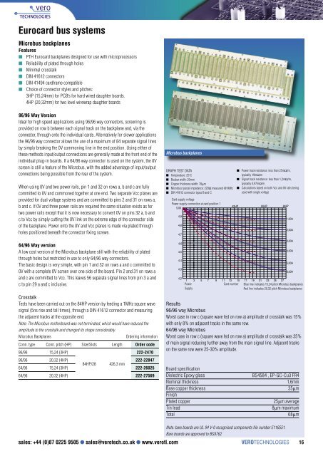
Microbus backplanes<br />
Features<br />
PTH Eurocard backplanes designed for use with microprocessors<br />
Reliability of plated through holes<br />
Minimal crosstalk<br />
DIN 41612 connectors<br />
DIN 41494 cardframe compatible<br />
Choice of connector styles <strong>and</strong> pitches:<br />
3HP (15,24mm) for PCB’s for hard wired daughter boards.<br />
4HP (20,32mm) for two level wirewrap daughter boards<br />
96/96 Way Version<br />
Ideal for high speed applications using 96/96 way connectors, screening is<br />
provided on row b between each signal track on <strong>the</strong> backplane <strong>and</strong>, via <strong>the</strong><br />
connector, through onto <strong>the</strong> individual cards. Alternatively for slower applications<br />
<strong>the</strong> 96/96 way connector allows <strong>the</strong> use of a maximum of 84 separate signal lines<br />
by simply breaking <strong>the</strong> 0V commoning line in <strong>the</strong> end position. Using ei<strong>the</strong>r of<br />
<strong>the</strong>se methods input/output connections are generally made at <strong>the</strong> front end of <strong>the</strong><br />
individual plug-in boards. If a 64/96 way connector is used on <strong>the</strong> system, <strong>the</strong> 0V<br />
screen is still a feature of <strong>the</strong> Microbus, with <strong>the</strong> added advantage of input/output<br />
connections being possible from <strong>the</strong> rear of <strong>the</strong> system.<br />
When using 0V <strong>and</strong> two power rails, pin 1 <strong>and</strong> 32 on rows a, b <strong>and</strong> c are fully<br />
committed to 0V <strong>and</strong> commoned toge<strong>the</strong>r at one end. Two separate Vcc planes are<br />
provided for dual voltage systems <strong>and</strong> are committed to pins 2 <strong>and</strong> 31 on rows a,<br />
b <strong>and</strong> c. If 0V <strong>and</strong> three power rails are required <strong>the</strong> same situation exists as for<br />
two power rails except that it is now necessary to convert 0V on pins 32 a, b <strong>and</strong><br />
c to Vcc by simply cutting <strong>the</strong> 0V link on <strong>the</strong> extreme edge of <strong>the</strong> connector side<br />
of <strong>the</strong> backplane. Power onto <strong>the</strong> 0V <strong>and</strong> Vcc planes is made via plated through<br />
holes positioned beneath <strong>the</strong> connector fixing screws.<br />
Microbus backplanes<br />
GRAPH TEST DATA<br />
Temperature: 25 o C<br />
Busbar width: 20mm<br />
Copper thickness width: 70µm<br />
Microbus typical impedance: 220Ω measured @1MHz<br />
DIN 41612 connector types B <strong>and</strong> C<br />
Card supply voltage<br />
Power supply connection at card position 1<br />
5,00<br />
4,9<br />
4,8<br />
4,7<br />
Power track resistance: less than 25mΩ/m,<br />
typically 19mΩ/m<br />
Signal track resistance: less than 1,2mΩ/m,<br />
typically 0,97mΩ/m<br />
Calculations based on both Vcc <strong>and</strong> 0V rails being<br />
used with single voltage<br />
42HP 60HP 84HP<br />
1,00A<br />
2,00A<br />
64/96 Way version<br />
A low cost version of <strong>the</strong> Microbus backplane still with <strong>the</strong> reliability of plated<br />
through holes but restricted in use to only 64/96 way connectors.<br />
The basic design is very simple, with pin 1 <strong>and</strong> 32 on rows a <strong>and</strong> c committed to<br />
0V with a complete 0V screen over one side of <strong>the</strong> board. Pin 2 <strong>and</strong> 31 on rows a<br />
<strong>and</strong> c are committed to Vcc. This leaves 56 separate signal lines from pin 3 a <strong>and</strong><br />
c to pin 29 a <strong>and</strong> c inclusive.<br />
4,6<br />
4,5<br />
4,4<br />
4,3<br />
4,2<br />
3,00A<br />
4,00A<br />
5,00A<br />
6,00A<br />
1 3 5 7 9 11 13 15 17 19 21 23 25 27<br />
Power<br />
Card number Blue line indicates 15,24 pitch Microbus backplanes<br />
Supply<br />
Red line indicates 20,32 pitch Microbus backplanes<br />
Crosstalk<br />
Tests have been carried out on <strong>the</strong> 84HP version by feeding a 1MHz square wave<br />
signal (5ns rise <strong>and</strong> fall times), through a DIN 41612 connector <strong>and</strong> measuring<br />
<strong>the</strong> adjacent tracks at <strong>the</strong> opposite end.<br />
Note: The Microbus mo<strong>the</strong>rboard was not terminated, which would have reduced <strong>the</strong><br />
amplitude to <strong>the</strong> crosstalk <strong>and</strong> changed its shape considerably.<br />
Microbus Backplanes<br />
Ordering information<br />
Conn. type Conn. pitch (HP) Size/Slots Length Order code<br />
96/96 15,24 (3HP)<br />
222-2470<br />
96/96 20,32 (4HP) 222-22847<br />
84HP/28 426,3 mm<br />
64/96 15,24 (3HP) 222-26025<br />
64/96 20,32 (4HP) 222-27569<br />
Results<br />
96/96 way Microbus<br />
Worst case in row c (square wave fed on row a) amplitude of crosstalk was 15%<br />
with only 8% on adjacent tracks in <strong>the</strong> same row.<br />
64/96 way Microbus<br />
Worst case in row c (square wave fed on row a) amplitude of crosstalk was 35%<br />
of main signal reducing fur<strong>the</strong>r away from <strong>the</strong> main signal line. Adjacent tracks<br />
on <strong>the</strong> same row were 25-30% amplitude.<br />
Board specification<br />
Dielectric Epoxy glass<br />
BS4584 , EP-GC-Cu3 FR4<br />
Nominal thickness<br />
1,6mm<br />
Base copper thickness 35µm<br />
Finish<br />
Plated copper<br />
25µm average<br />
Tin lead<br />
8µm maximum<br />
Total 68µm<br />
Note: bare boards are UL 94 V-0 recognised components file number E116551.<br />
Bare boards are approved to BS9762<br />
sales: +44 (0)87 0225 9505 sales@verotech.co.uk www.verotl.com VEROTECHNOLOGIES 16