Worcester Controls 75 Series Electronic Actuator 10-23 Motor ...
Worcester Controls 75 Series Electronic Actuator 10-23 Motor ...
Worcester Controls 75 Series Electronic Actuator 10-23 Motor ...

Create successful ePaper yourself
Turn your PDF publications into a flip-book with our unique Google optimized e-Paper software.
<strong>Series</strong> <strong>75</strong> <strong>10</strong>-<strong>23</strong><br />
<strong>Motor</strong> Module<br />
FCD WCAIM2066-00 (Part 09534)<br />
Installation, Operation and Maintenance<br />
<strong>Motor</strong> module kits are intended as repair kits for <strong>10</strong>-<strong>23</strong> <strong>75</strong> electric<br />
actuators. Diagrams show typical installation of these kits, which<br />
should be installed exactly as the motor modules they are replacing.<br />
a CAUTION: Be sure actuator is disconnected from power<br />
source.<br />
To replace a motor module, do the following:<br />
1. Remove the four 8-32 slotted hex head screws (and on <strong>23</strong><br />
size only, the four 6-32 slotted screws on the outside corners<br />
of motors) that secure the motor module in place. (A motor<br />
module is the complete motor/gearbox assembly.)<br />
2. Disconnect the electrical leads as follows:<br />
AC: Loosen terminal strip screw at terminal 1, to which white<br />
motor lead is secured, and remove white wire. Remove all wiring<br />
connectors at the capacitor.<br />
DC: Using a wire cutter, cut all lead wires at the closed end<br />
splice, as close to this splice as possible.<br />
Loosen terminal strip screw at terminal 1, to which the red<br />
wire(s) are attached, and remove red wire(s).<br />
Strip ¼" of insulation from each end of the blue wires that were<br />
spliced.<br />
3. Cut cable ties as required and remove motor module from the<br />
actuator.<br />
4. On AC voltage actuators remove and replace capacitor. Position<br />
capacitor with connectors at 45° to base so that leads do not<br />
touch cover.<br />
5. Install the new motor module, securing in place with the four<br />
8-32 mounting screws. Locate the motor module in the identical<br />
manner as it was removed.<br />
NOTE: For <strong>23</strong> size only, four additional screws on the outside<br />
corners of motors are also used to secure motor module. Prior<br />
to mounting, remove any temporary fasteners holding these<br />
screws in place.<br />
6. Reconnect motor leads, as shown, keeping all wires away from<br />
any rotating parts (shaft and motor module pinion). Wiring to<br />
terminal strip should be inserted only to midpoint of terminal<br />
strip.<br />
DC: Using the new closed end splice, insert the blue leads and<br />
black motor lead(s) into the splice and crimp it closed. Tuck the<br />
splice underneath the limit switch.<br />
7. The actuator’s cam settings are not affected by changing a<br />
motor module. Operate actuator to verify proper operation.<br />
8. Replace cable ties, as shown. Trim off excess tie and revolve so<br />
as to not interfere with cover.<br />
9. SPECIAL NOTE<br />
AC <strong>Actuator</strong>s: Observe the following when installing AC motor<br />
modules:<br />
When the motor module is located with “output-fast” closest to<br />
center shaft, connect actuator wires, as shown (<strong>10</strong>, 15 and 20<br />
size actuators). For <strong>23</strong> size only, wires are connected as shown,<br />
except that motor module is located with “output-slow” closest<br />
to center shaft.
Flow Control<br />
<strong>Worcester</strong> Actuation Systems<br />
When the motor module is located with “output-slow” closest<br />
to center shaft, connect actuator wires as shown except<br />
interchange grey and yellow motor leads at the motor capacitor<br />
(12 and 22 size actuators). If capacitor has metal retaining ring,<br />
insulating fiber washer must be used.<br />
For 20 <strong>75</strong> actuators, <strong>10</strong>0% duty cycle, the motor module is<br />
mounted to the actuator with the “output-slow” closest to the<br />
center shaft. As before, interchange the grey and yellow leads<br />
from the motor at the capacitor. If capacitor has metal retaining<br />
ring, insulating fiber washer must be used.<br />
SPECIAL NOTE<br />
DC <strong>Actuator</strong>s: Observe the following when installing DC motor<br />
modules:<br />
When the motor module is located with “output-fast” closest to<br />
the center shaft, connect actuator wires as shown (<strong>10</strong> and 20<br />
size actuators). For <strong>23</strong> size only, wires are connected as shown,<br />
except that motor module is located with “output-slow” closest<br />
to center shaft.<br />
When the motor module is located with “output-slow” closest<br />
to the center shaft, connect actuator wires as shown, except<br />
interchange the wiring location of the motor’s red and black<br />
leads. The black wire(s) are connected to terminal 1, while the<br />
red wire(s) are crimped with the blue wires (12 and 22 size<br />
actuators).<br />
Alternatively, the supply voltage polarity may be reversed to<br />
accomplish the same thing. That is, if the motor module is<br />
located with “output-slow” closest to the center shaft, simply<br />
reverse supply voltage polarity for proper operation. Never do<br />
both!<br />
If in special circumstances DC motor is mounted on top of gearbox<br />
from AC motor module, the bearing from gearbox has to be<br />
removed to eliminate bindings. (DC motor has two bearings in<br />
the housing already.)<br />
2 <strong>Series</strong> <strong>75</strong> <strong>10</strong>-<strong>23</strong> <strong>Motor</strong> Module FCD WCAIM2066-00
Flow Control<br />
<strong>Worcester</strong> Actuation Systems<br />
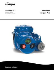
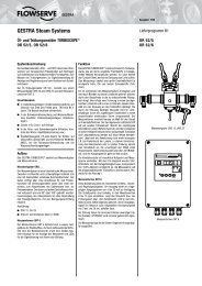
Figure 1: <strong>10</strong> <strong>75</strong> 120/240A<br />
15 <strong>75</strong> 120A<br />
Figure 2: 20 <strong>75</strong> 120/240A<br />
<br />
<br />
<br />
<br />
<br />
<br />
<br />
<br />
<br />
<br />
<br />
<br />
<br />
<br />
<br />
<br />
<br />
<br />
<br />
<br />
<br />
<br />
<br />
<br />
<br />
<br />
<br />
<br />
<br />
<br />
<br />
<br />
<br />
<br />
<br />
<br />
<br />
<br />
<br />
<br />
Figure 3: <strong>10</strong> <strong>75</strong> 12/24D Figure 4: 20 <strong>75</strong> 12/24D<br />
<br />
<br />
<br />
<br />
<br />
<br />
<br />
<br />
<br />
<br />
<br />
<br />
<br />
<br />
<br />
<br />
<br />
<br />
<br />
<br />
<br />
<br />
<br />
<br />
<br />
FCD WCAIM2066-00 <strong>Series</strong> <strong>75</strong> <strong>10</strong>-<strong>23</strong> <strong>Motor</strong> Module 3
Flowserve Corporation has established industry leadership in the design and manufacture<br />
of its products. When properly selected, this Flowserve product is designed to<br />
perform its intended function safely during its useful life. However, the purchaser or<br />
user of Flowserve products should be aware that Flowserve products might be used in<br />
numerous applications under a wide variety of industrial service conditions. Although<br />
Flowserve can (and often does) provide general guidelines, it cannot provide specific<br />
data and warnings for all possible applications. The purchaser/user must therefore<br />
assume the ultimate responsibility for the proper sizing and selection, installation, operation,<br />
and maintenance of Flowserve products. The purchaser/user should read and<br />
understand the Installation Operation Maintenance (IOM) instructions included with the<br />
product, and train its employees and contractors in the safe use of Flowserve products<br />
in connection with the specific application.<br />
While the information and specifications contained in this literature are believed to be<br />
accurate, they are supplied for informative purposes only and should not be considered<br />
certified or as a guarantee of satisfactory results by reliance thereon. Nothing contained<br />
herein is to be construed as a warranty or guarantee, express or implied, regarding any<br />
matter with respect to this product. Because Flowserve is continually improving and<br />
upgrading its product design, the specifications, dimensions and information contained<br />
herein are subject to change without notice. Should any question arise concerning<br />
these provisions, the purchaser/user should contact Flowserve Corporation at any one<br />
of its worldwide operations or offices.<br />
For more information about Flowserve Corporation, visit www.flowserve.com or call<br />
USA 1-800-225-6989.<br />
FLOWSERVE CORPORATION<br />
Flow Control<br />
<strong>Worcester</strong> Actuation Systems<br />
5114 Woodall Road<br />
P.O. Box 11318<br />
Lynchburg, VA 24506-1318<br />
Phone: 434-528-4400<br />
Fax: 434-845-9736<br />
(Part 09354)<br />
© 2004 Flowserve Corporation, Irving, Texas, USA. Flowserve is a registered trademark of Flowserve Corporation. FCD WCAIM2066-00 Printed in USA.