GOPAG® C 500 F - SANGER METAL
GOPAG® C 500 F - SANGER METAL
GOPAG® C 500 F - SANGER METAL

You also want an ePaper? Increase the reach of your titles
YUMPU automatically turns print PDFs into web optimized ePapers that Google loves.
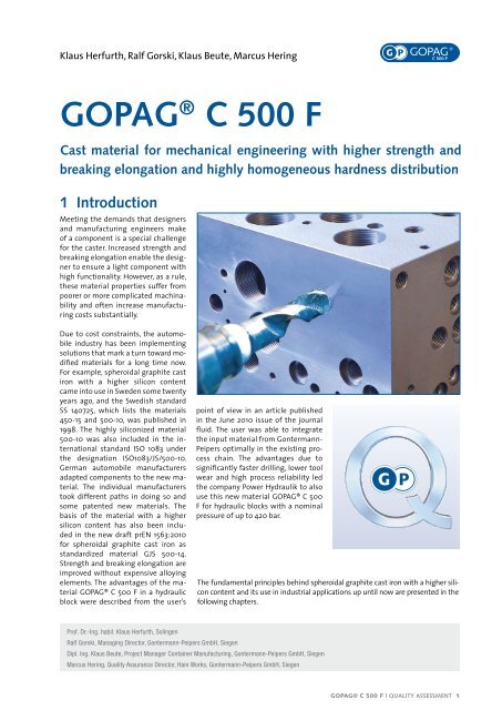
Klaus Herfurth, Ralf Gorski, Klaus Beute, Marcus Hering<br />
GOPAG ® C <strong>500</strong> F<br />
Cast material for mechanical engineering with higher strength and<br />
breaking elongation and highly homogeneous hardness distribution<br />
1 Introduction<br />
Meeting the demands that designers<br />
and manufacturing engineers make<br />
of a component is a special challenge<br />
for the caster. Increased strength and<br />
breaking elongation enable the designer<br />
to ensure a light component with<br />
high functionality. However, as a rule,<br />
these material properties suffer from<br />
poorer or more complicated machinability<br />
and often increase manufacturing<br />
costs substantially.<br />
Due to cost constraints, the automobile<br />
industry has been implementing<br />
solutions that mark a turn toward modified<br />
materials for a long time now.<br />
For example, spheroidal graphite cast<br />
iron with a higher silicon content<br />
came into use in Sweden some twenty<br />
years ago, and the Swedish standard<br />
SS 140725, which lists the materials<br />
450-15 and <strong>500</strong>-10, was published in<br />
1998. The highly siliconized material<br />
<strong>500</strong>-10 was also included in the international<br />
standard ISO 1083 under<br />
the designation ISO1083/JS/<strong>500</strong>-10.<br />
German automobile manufacturers<br />
adapted components to the new material.<br />
The individual manufacturers<br />
took different paths in doing so and<br />
some patented new materials. The<br />
basis of the material with a higher<br />
silicon content has also been included<br />
in the new draft prEN 1563:2010<br />
for spheroidal graphite cast iron as<br />
standardized material GJS <strong>500</strong>-14.<br />
Strength and breaking elongation are<br />
improved without expensive alloying<br />
elements. The advantages of the material<br />
<strong>GOPAG®</strong> C <strong>500</strong> F in a hydraulic<br />
block were described from the user’s<br />
point of view in an article published<br />
in the June 2010 issue of the journal<br />
fluid. The user was able to integrate<br />
the input material from Gontermann-<br />
Peipers optimally in the existing process<br />
chain. The advantages due to<br />
significantly faster drilling, lower tool<br />
wear and high process reliability led<br />
the company Power Hydraulik to also<br />
use this new material <strong>GOPAG®</strong> C <strong>500</strong><br />
F for hydraulic blocks with a nominal<br />
pressure of up to 420 bar.<br />
The fundamental principles behind spheroidal graphite cast iron with a higher silicon<br />
content and its use in industrial applications up until now are presented in the<br />
following chapters.<br />
Prof. Dr.-Ing. habil. Klaus Herfurth, Solingen<br />
Ralf Gorski, Managing Director, Gontermann-Peipers GmbH, Siegen<br />
Dipl. Ing. Klaus Beute, Project Manager Container Manufacturing, Gontermann-Peipers GmbH, Siegen<br />
Marcus Hering, Quality Assurance Director, Hain Works, Gontermann-Peipers GmbH, Siegen<br />
<strong>GOPAG®</strong> C <strong>500</strong> F | QUALITY ASSESSMENT 1
2 Increasing the strength of cast iron through increased use of<br />
solid solution strengthening<br />
2.1. Solid solution strengthening<br />
through higher silicon concen -<br />
trations<br />
Solid solution strengthening changes<br />
the mechanical properties of crystal <br />
li ne solids by adding intersital or substitu<br />
tional atoms; intersital or substitutio<br />
nal solid solutions form. Crystalline<br />
solids with a long-range atomic order<br />
have a regular crystalline structure. If solute<br />
atoms are added to the crystalline<br />
structure, the lattice is distorted. Solute<br />
atoms with a similar atomic radius<br />
replace solvent atoms in their lattice<br />
posi tions; substantially smaller atoms<br />
occupy an intersital site. The distor <br />
tion of the lattice inhibits sliding movements<br />
in the crystal. These processes at<br />
the atomic level result in an increase in<br />
strength and a reduction in plasticity.<br />
In cast iron materials, the iron-carbonsilicon<br />
alloys, the silicon is added to the<br />
body-cantered cubic lattice of the α-solid<br />
solution (ferrite) at substitutional positions;<br />
silicon atoms replace iron atoms<br />
in the lattice. The carbon occupies intersital<br />
sites in the α-solid solutions.<br />
2.2. Solid solution strengthening in<br />
cast iron<br />
Solid solution strengthening in spheroidal<br />
graphite cast iron by silicon is a<br />
known fact. Fig. 1 shows the influence<br />
of silicon content on the mechanical<br />
properties of ferritic spheroidal graphite<br />
cast iron /1/. Tensile strength,<br />
0.2% proof stress and Brinell hardness<br />
increase as silicon content increases.<br />
Breaking elongation, on the other<br />
hand, decreases. As silicon content<br />
increases, the transition temperature<br />
shifts to higher temperatures /2/.<br />
In spheroidal graphite cast iron as a<br />
Fe-Si-C material, solid solution streng <br />
thening already takes effect as a property<br />
forming mechanism with a silicon<br />
content of approx. 2.6%.<br />
In ferritic spheroidal graphite cast iron<br />
according to EN 1563, breaking elongations<br />
of 15 to 22% are attained with<br />
samples taken from separately cast test<br />
specimens with tensile strengths of<br />
350 to 400 N/mm 2 . In connection with<br />
the material grade EN-GJS-<strong>500</strong>-7C<br />
with a minimum of <strong>500</strong> N/mm 2 and<br />
7% breaking elongation, an interesting<br />
thought originated some 15 years ago:<br />
This type of cast iron has a metallic<br />
Fig. 1: Dependency of tensile strength, 0.2% proof stress, breaking elongation and<br />
hardness on silicon content in ferritic spheroidal graphite cast iron /1/<br />
Tensile strength<br />
and 0.2 % proof stress in N/mm 2<br />
600<br />
<strong>500</strong><br />
400<br />
300<br />
200<br />
Tensile strength<br />
0.2% proof stress<br />
2 3 4<br />
Breaking elongation in %<br />
basic matrix consisting of a specific<br />
proportion of ferrite and perlite. It<br />
is not always possible to adjust this<br />
mixed structure of the metallic base<br />
material stably in production. The result<br />
is a relatively high varia tion in<br />
Brinell hardness that can lead to difficulties<br />
in machining. Development<br />
projects originated with the objective<br />
of producing the material grade EN-<br />
GJS-<strong>500</strong>-7C with a purely ferritic basic<br />
matrix through higher silicon concentrations<br />
to attain lower variations in<br />
Brinell hardness. Higher silicon concentrations<br />
inhibit perlite formation<br />
during eutectoid transformation, and<br />
40<br />
30<br />
20<br />
10<br />
Silicon content in %<br />
Breaking elongation<br />
Hardness<br />
2 3 4<br />
250<br />
200<br />
150<br />
Hardness HB<br />
stronger solid solution strengthening<br />
occurs.<br />
For a long time, further solid solution<br />
strengthening through higher silicon<br />
concentrations was thought to be unusable<br />
because of the simultaneous<br />
tendency towards brittleness. However,<br />
more recent investigations /3 to 7/<br />
indicate that very interesting combinations<br />
of mechanical properties can<br />
be attained with higher silicon concentrations.<br />
The results of this research<br />
and development work are described<br />
below.<br />
2.3. Research and development work<br />
in the recent past (sand casting)<br />
In connection with the production of<br />
large castings with wall thicknesses<br />
of 60 to 200 mm, the intention was<br />
to achieve a reduction in weight using<br />
a high-strength grade of spheroidal<br />
graphite cast iron /4/. Researchers investigated<br />
the influence of alloying<br />
elements (Cu, Mn, Ni, Mo, Si, Nb), in ocu-<br />
lants and inoculation treatment and<br />
cooling conditions. The specimen were<br />
removed from a wedge shaped test<br />
block measuring 100 to 600 x 1000 x<br />
<strong>500</strong> mm. The results were checked in a<br />
press frame for an internal high-pressure<br />
forming machine with wall thicknesses<br />
of 60 to 200 mm in samples from<br />
cast-on test specimen. A spheroidal<br />
graphite cast iron with the following<br />
chemical composition led to success:<br />
3.10% C, 3.75% Si, 0.22% Mn, 0.016% P,<br />
0.005% S and 0.044% Mg. This resulted<br />
in a spheroidal graphite cast iron<br />
with a purely ferritic basic matrix without<br />
heat treatment.<br />
2 | <strong>GOPAG®</strong> C <strong>500</strong> F | QUALITY ASSESSMENT
The following mechanical properties<br />
were attained: With cast-on samples<br />
517 - 521 N/mm 2 tensile strength,<br />
413 - 417 N/mm 2 , 0.2% proof stress,<br />
14.0 - 14.5% breaking elongation, 20%<br />
breaking contraction, and 171.6 - 173.3<br />
kN/mm 2 elastic modulus. In samples<br />
from the test block 485 - 505 N/mm 2<br />
tensile strength, 393 - 395 N/mm 2<br />
proof stress, 10 - 16% breaking elongation,<br />
8.5 - 15% breaking contraction<br />
depending on the location in the<br />
test block. The tensile strength, proof<br />
stress, breaking elongation and breaking<br />
contraction within the temperature<br />
range of -80 °C to + 300 °C are<br />
reported (Fig. 2).<br />
In machining of motor vehicle components<br />
consisting of the ferrtic-perlitic<br />
material grade EN-GJS-<strong>500</strong>-7 with a<br />
silicon content of 2.25%, difficulties<br />
were observed during turning, milling<br />
and drilling because of the relatively<br />
large Brinell hardness range (170 to<br />
230 HB). However this was caused by<br />
fluctuations in perlite content because<br />
of varying rates of cooling in the castings<br />
during eutectoid transformation.<br />
Research and development of spheroidal<br />
graphite cast iron and higher silicon<br />
concentrations of (3.66 to 3.85%)<br />
led to success /3, 5/. This resulted in a<br />
material grade of sphe roidal graphite<br />
cast iron with a purely ferritic metallic<br />
base material with the following mechanical<br />
properties: Ten sile strength<br />
at least <strong>500</strong> N/mm 2 , 0.2% proof stress<br />
at least 360 N/mm 2 , breaking elongation<br />
at least 10% and a hardness range<br />
of 185 to 215 HB. The more homogenous<br />
distribution of hardness in the<br />
castings (plus/minus 20 HB) made it<br />
possible to reduce cutting tool wear<br />
and increase cutting speed. In addition,<br />
the noise level during machining<br />
also decreased. The cost reduction was<br />
stated to be 10%. The optimum chemical<br />
composition was stated to be as<br />
follows: 3.3% C, 3.75% Si, max. 0.3% Mn,<br />
max. 0.05% P, max. 0.03% S and 0.02<br />
to 0.08% Mg. The following material<br />
parameters were stated as a recommendation<br />
for a new grade of spheroidal<br />
graphite cast iron: Minimum<br />
tensile strength <strong>500</strong> N/mm 2 , min. 0.2%<br />
proof stress 360 N/mm 2 , min. breaking<br />
elongation A5 10%, Brinell hardness<br />
185 to 215. The new grade of silicon-rich<br />
spheroidal graphite cast iron GJS-<strong>500</strong>-<br />
10 with a ferritic matrix was standardized<br />
in Swedish standard SS14 07 25<br />
„Spheroidal graphite cast iron - SS cast<br />
iron 0725“. 1998-03-18.<br />
R. Larker /6/ dealt with solid solution<br />
strengthened ferritic spheroidal graphite<br />
cast iron for the use of such castings<br />
in hydraulically actuated equipment.<br />
With these cast components, it<br />
is necessary to attain very high manufacturing<br />
accuracy during machining.<br />
Values for tensile strength, 0.2%<br />
proof stress and breaking elongation<br />
are stated as a function of the silicon<br />
concentration within the range of 2.25<br />
to 4.2% Si with the known tendencies<br />
that strength and hardness increase<br />
and ductility (breaking elongation),<br />
on the other hand, decreases as silicon<br />
content increases. A silicon content<br />
of 3.7% is preferred for development<br />
of a material grade with a ferritic<br />
base material. Because of the much<br />
lower variations in Brinell hardness<br />
over the casting cross-section (Fig. 3), –<br />
± 2.6 through the use of material grade<br />
GJS-<strong>500</strong>-10 in comparison with ± 10<br />
when using material grade GJS-<strong>500</strong>-7 –<br />
machinability improved by 20 to 30%.<br />
Experts caution against the formation<br />
of chunky graphite. This undesirable<br />
form of graphite substantially impairs<br />
the favourable mechanical properties<br />
in the material grade GJS-<strong>500</strong>-10.<br />
The material grade GJS-<strong>500</strong>-10 was<br />
included in international standardization<br />
with the designation ISO 1083/<br />
JS/<strong>500</strong>-10 (2004).<br />
Fig. 2: Influence of the test temperature on material characteristics in the tensile test /4/<br />
%<br />
N/mm 2<br />
30,0<br />
25,0<br />
20,0<br />
15,0<br />
10,0<br />
5,0<br />
0,0<br />
-80 -30 20 70 120 170 220 270 320<br />
A<br />
Rpo,2<br />
Z<br />
520<br />
<strong>500</strong><br />
480<br />
460<br />
440<br />
420<br />
400<br />
380<br />
360<br />
340<br />
320<br />
300<br />
-80 -30 20 70 120 170 220 270 320<br />
Rm<br />
Test temperature °C<br />
Fig. 3: Swivel housing: Distribution of the Brinell hardness over the cross-section of the<br />
casting when GJS-<strong>500</strong>-7 or GJS-<strong>500</strong>-10 is used /6/<br />
<strong>GOPAG®</strong> C <strong>500</strong> F | QUALITÄTSBEWERTUNG 3
J. Kikkert /7/ dealt, proceeding from<br />
material grade GJS-<strong>500</strong>-10, with the<br />
development of the material grades<br />
GJS-450-18, GJS-<strong>500</strong>-14 and GJS-600-10<br />
using higher silicon concentrations of<br />
3.5 to 5.4% Si in the spheroidal graphite<br />
cast iron. Fig. 4 conveys an impres sion<br />
of the influence of the silicon content<br />
on the tensile strength and 0.2% proof<br />
stress. Solid solution strengthening<br />
has an effect until the silicon content<br />
reaches 4.5%. The breaking elongation<br />
(Fig. 5) decreases only slightly until silicon<br />
content reaches 4.5%, but drops<br />
sharply at higher silicon concentrations.<br />
Fig. 6 shows the fatigue strength<br />
for a swivel bearing made of different<br />
grades of spheroidal graphite cast<br />
iron, whereby the silicon-rich material<br />
grade GJS-600-10 performs well. This<br />
leads to the conclusion that the solid<br />
solution strengthening caused by silicon<br />
can be used up to tensile strengths<br />
exceeding 600 N/mm 2 . The representation<br />
of Brinell hardness and 0.2%<br />
proof stress (Fig. 7) clearly reveals that<br />
the fluctuations in Brinell hardness<br />
are significantly lower with the ferritic<br />
material grades GJS-<strong>500</strong>-14 and GJS-<br />
600-10 than with the traditional material<br />
grades GJS-<strong>500</strong>-7 and GJS-600-3. J.<br />
Kikkert /7/ therefore proposes that the<br />
material grades GJS-450-18, GJS-<strong>500</strong>-14<br />
and GJS-600-10 be included in European<br />
standardization (Table 02 - p. 6)<br />
and speaks in this connection of the second<br />
generation of spheroidal graphite<br />
cast iron.<br />
Fig. 4: Dependence of tensile strength and proof stress on silicon content in spheroidal<br />
graphite cast iron /7/<br />
0.2% proof stress,<br />
tensile strength N/mm 2<br />
Breaking elongation A (%)<br />
25<br />
20<br />
15<br />
10<br />
5<br />
0<br />
700<br />
650<br />
600<br />
550<br />
<strong>500</strong><br />
450<br />
400<br />
Cast sample 25 mm diameter Rp 0,2<br />
Cast sample 25 mm diameter Rm<br />
IfG/25 mm Y-2 sample Rp 0,2<br />
IfG/25 mm Y-2 sample Rm<br />
350<br />
3,5 4 4,5 5<br />
5,5<br />
Si content (%)<br />
Fig. 5: Dependence of breaking elongation on silicon content in spheroidal graphite<br />
cast iron /7/<br />
Cast sample 25 mm diameter<br />
Cast specimen (30 mm)<br />
IfG/25 mm Y-2 sample<br />
3,5 4 4,5 5<br />
5,5<br />
Si content (%)<br />
Fig. 6: Fatigue strength for a swivel bearing for the material grade GJS-600-10<br />
compared with other material grades /7/<br />
Stress amplitude N/mm 2<br />
700<br />
650<br />
600<br />
550<br />
<strong>500</strong><br />
450<br />
400<br />
350<br />
Swivel bearing (prGJS-600-10: 83% nodularity)<br />
GJS-600-10<br />
GJS-700-2<br />
GJS-800-10<br />
300<br />
250<br />
1,0E+02 1,0E+03 1,0E+04 1,0E+05 1,0E+06 1,0E+07<br />
Table 01: Mechanical properties of material<br />
grade <strong>GOPAG®</strong> C <strong>500</strong> F for various<br />
continuous casting dimensions<br />
Mechanical properties<br />
Fig. 7: Dependence of the Brinell hardness on the 0.2% proof stress for the material grades<br />
GJS-<strong>500</strong>-7 and GJS-600-3 or GJS-<strong>500</strong>-14 and GJS-600-10<br />
280<br />
Number of vibration examples until breaking<br />
Dimension<br />
t (mm)<br />
60 t 120 120 t 400<br />
Tensile strength<br />
490 470<br />
R m<br />
(N/mm 2 )<br />
Proof stress<br />
370 360<br />
R p0,2<br />
(N/mm 2 )<br />
Brinell hardness HBW<br />
260<br />
240<br />
220<br />
200<br />
180<br />
EN-GJS-<strong>500</strong>-7<br />
EN-GJS-600-3<br />
prGJS-<strong>500</strong>-14<br />
prGJS-600-10<br />
Elongation<br />
A (%)<br />
12 10<br />
160<br />
300 320 340 360 380 400 420 440 460 480 <strong>500</strong> 520 540<br />
0,2% proof stress N/mm 2<br />
4 | <strong>GOPAG®</strong> C <strong>500</strong> F | QUALITY ASSESSMENT
3 Research and development at<br />
Gontermann-Peipers (continuous casting)<br />
All of the previously described findings<br />
were determined in the production<br />
of castings using the sand<br />
casting process. In continuous casting<br />
of spheroidal graphite cast iron,<br />
the conditions during solidification<br />
and further cooling are different from<br />
those in the sand casting process.<br />
Continuous castings made of cast<br />
iron are produced using the horizontal<br />
continuous casting method. The<br />
procedure, the peculiarities of this<br />
method, and the attainable mechanical<br />
properties, in conjunction with<br />
a proposal for European standar <br />
di za tion (EN), have been described<br />
in works /8, 9/. Gontermann-Peipers<br />
supplies continuous cast sections of<br />
specific lengths either unfinished or<br />
semi-fi niched. Gontermann-Peipers also<br />
offers semi-finishing on all sides to<br />
nearly finished dimensions according<br />
to customer wishes. This prevents customers<br />
having to perform additional<br />
operations.<br />
In connection with the advancement<br />
of continuous casting of spheroidal<br />
gra phite cast iron with solid solution<br />
strengthening, Gontermann-Peipers (GP)<br />
presented the material grade <strong>GOPAG®</strong><br />
C <strong>500</strong> F (GP-protected brand name) with<br />
a ferritic matrix in the casting state, in<br />
comparison with GJS-<strong>500</strong>-7C. (Fig. 8).<br />
Fig. 8a shows the microstructure of<br />
<strong>GOPAG®</strong> C <strong>500</strong> F with a ferritic matrix<br />
and Fig. 8b the microstructure of GJS-<br />
<strong>500</strong>-7C with a matrix of ferrite and<br />
approx. 30% perlite. The formation of<br />
perlite and thus the extremely hard<br />
cementite contained in it is largely inhibited<br />
by the higher silicon content.<br />
This material grade <strong>GOPAG®</strong> C <strong>500</strong> F<br />
complies with the specifications in<br />
European standards for spheroidal<br />
graphite cast iron, which is designated<br />
GJS-<strong>500</strong>-14C. The following<br />
non-binding reference values are<br />
stated for the chemical composition<br />
of this material grade: 2.80 to<br />
3.80% C, 3.30 to 3.90% Si, 0.025 to<br />
Fig. 8: Structure of continuous cast iron: a) GOPAG ® C <strong>500</strong> F<br />
b) Microstructure GJS-<strong>500</strong>-7C 8a<br />
0.075% Mg, max. 0.1% Cu. In conformity<br />
with the cast iron standards DIN<br />
EN 1561 and DIN EN 1563, these details<br />
regarding the chemical analysis are<br />
non-binding manufacturer’s reference<br />
values.<br />
The samples used to determine the<br />
mechanical properties are removed<br />
directly from the strand (Fig. 9),<br />
marked with the letter „C“ /8/. The<br />
stress-strain curves for the material<br />
grade <strong>GOPAG®</strong> C <strong>500</strong> F in comparison<br />
with a forged steel typically used in<br />
the hydraulics sector (Fig.10) clearly<br />
show the plastic range with the breaking<br />
elongation after the 0.2% proof<br />
stress. The mechanical properties attained<br />
for the new material grade are<br />
shown in Table 01 - page 4 for various<br />
continuous casting shapes.<br />
For the new material grade <strong>GOPAG®</strong><br />
C <strong>500</strong> F, it is readily apparent that the<br />
mechanical properties can be produced<br />
within stringent tolerances on a production<br />
scale, whereby the narrow tolerance<br />
range for the breaking elongation<br />
particularly stands out.<br />
8a<br />
Fig. 9: Sampling for the determination of<br />
the mechanical properties of conti -<br />
nuous cast iron<br />
Magnification: V=100:1 Magnification: V=200:1 Magnification: V=<strong>500</strong>:1<br />
Werkstoff: GOPAG ® C <strong>500</strong> F<br />
Gefüge: 100% ferrite<br />
visual assessment<br />
8b<br />
D/4<br />
Round bars<br />
H<br />
B<br />
Rectangular bars B > H<br />
H/4<br />
Magnification: V=100:1 Magnification: V=200:1 Magnification: V=<strong>500</strong>:1<br />
Material:<br />
Structure:<br />
EN-GJS-<strong>500</strong>-7C<br />
approx. 30% perlite, rest ferrite<br />
visual assessment<br />
Semicircular bars<br />
H/4<br />
<strong>GOPAG®</strong> C <strong>500</strong> F | QUALITY ASSESSMENT 5
Fig. 10: Stress-elongation curve for GOPAG ® C <strong>500</strong> F compared with a<br />
forged steel typically used in the hydraulics sector<br />
Fig. 11<br />
600<br />
2<br />
Stress-elongation<br />
Forged steel<br />
400<br />
GOPAG ® C <strong>500</strong> F<br />
200<br />
0 0 10 20 30<br />
Elongation in %<br />
Machine type: UPD350KN Transducer: ZWICK ASM WS11-2000-ROD450<br />
Manufacturer: MFL/ZWICK Software: testXpert II<br />
Fig. 12<br />
Fig. 13<br />
Table 02: Mechanical properties, excerpt of prEN 1563:2009<br />
prEN 1563:2009 – Mechanical properties measured on test pieces machined<br />
from cast sample for solid solution strengthened ferritic grades<br />
Material designation<br />
Symbol<br />
Number<br />
EN-GJS-450-18 5.3107<br />
EN-GJS-<strong>500</strong>-14 5.3109<br />
EN-GJS-600-10 5.3110<br />
Relevant<br />
wall thickness<br />
t<br />
mm<br />
0,2% proof<br />
stress<br />
Rp0,2<br />
N/mm 2<br />
min.<br />
Tensile<br />
strength<br />
Rm<br />
N/mm 2<br />
min.<br />
Elongation<br />
A<br />
%<br />
min.<br />
t 30 350 450 18<br />
30 t 60 340 430 14<br />
60 t 200 a a a<br />
t 30 400 (360) 1 <strong>500</strong> (<strong>500</strong>) 1 14 (10) 1<br />
30 t 60 390 (360) 1 480 (490) 1 12 (9) 1<br />
60 t 200 a (350) 1 a (470) 1 a (7) 1<br />
t 30 450 600 10<br />
30 t 60 430 580 8<br />
60 t 200 a a a<br />
a To be agreed between the manufacturer and the purchaser<br />
1)<br />
ISO 1083/JS<strong>500</strong>-10/U<br />
Fig. 14<br />
Fig. 15<br />
MPa<br />
%<br />
Fig. 11, 12, 13 and 14 show the outstanding<br />
process capability for GOPAG ®<br />
C <strong>500</strong> F measured in terms of tensile<br />
strength, 0.2% proof stress, breaking<br />
elongation and Brinell hardness.<br />
The characteristic values for the 0.2%<br />
proof stress, tensile strength and breaking<br />
elongation as a function of Brinell<br />
hardness for GOPAG ® C <strong>500</strong> F are illustrated<br />
in Fig. 15.<br />
The hardness distribution across the<br />
strand cross-section is shown in Fig.16.<br />
The hardness range is substantially larger<br />
with the material GJS-<strong>500</strong>-7 with<br />
185 to 220 HBW 5/750 than with the<br />
material GJS-<strong>500</strong>-14C (<strong>GOPAG®</strong> C <strong>500</strong><br />
F) with 172 to 188 HBW 5/750. The difference<br />
in hardness relative to the previous<br />
<strong>500</strong> material is 35 HBW in the first<br />
case and 16 HBW in the second case<br />
with the new material.<br />
Fig. 11: Representation of the process capability<br />
for the tensile strength Rm in<br />
N/mm² for GOPAG ® C <strong>500</strong> F<br />
Fig. 12: Representation of the process<br />
capability for the 0.2% proof stress<br />
Rp 0.2 in N/mm² for<br />
GOPAG ® C <strong>500</strong> F<br />
Fig. 13: Representation of the process capability<br />
for the breaking elongation A<br />
in % for GOPAG ® C <strong>500</strong> F<br />
Fig. 14: Representation of the process capability<br />
for the Brinell hardness HBW<br />
for GOPAG ® C <strong>500</strong> F<br />
Fig. 15: 0.2% proof stress, tensile strength<br />
and breaking elongation as<br />
a function of Brinell hardness for<br />
GOPAG ® C <strong>500</strong> F<br />
6 | <strong>GOPAG®</strong> C <strong>500</strong> F | QUALITY ASSESSMENT
Fig. 16: Hardness distribution over the<br />
cross-section<br />
a) GJS-<strong>500</strong>-7<br />
b) GOPAG ® C <strong>500</strong> F<br />
Thus it is apparent that solid solution<br />
strengthening with higher silicon<br />
concentrations leads to a predominantly<br />
ferritic microstructure with<br />
high strength and high breaking<br />
elongation in both sand casting and<br />
continuous casting. The material<br />
grade GJS-<strong>500</strong>-14C can be produced<br />
without perlite components with a<br />
higher breaking elongation and has<br />
an outstanding yield strength/tensile<br />
strength ratio of approx. 0.8.<br />
A significant amount of continuously<br />
cast spheroidal graphite cast iron<br />
material is used for hydraulic control<br />
blocks (Fig. 17). The company Power-<br />
Hydraulik GmbH /11/ has already had<br />
very positive experiences with the<br />
aforementioned material over a long<br />
period of time. The material GJS-<strong>500</strong>-<br />
7C was no longer suitable for higher<br />
internal hydrostatic pressures in<br />
the range of 350 to 420 bar. In 2009,<br />
Gontermann-Peipers introduced the<br />
new continuous cast iron with the designation<br />
<strong>GOPAG®</strong> C <strong>500</strong> F. Thus now<br />
forged steel can be replaced even at<br />
higher internal hydrostatic pressures.<br />
External inspection of such hydraulic<br />
control blocks reveals only a row<br />
of holes. On the inside, they contain<br />
an extensive system of intertwined<br />
channels (Fig. 18). This channel system<br />
is produced by drilling. Approx.<br />
one third of the original weight of the<br />
hydraulic control blocks is removed<br />
by drilling. Cylindrical grinding or circular<br />
milling, reaming, honing and<br />
thread cutting are used as additional<br />
processing technologies. This extensive<br />
drilling requires a material with<br />
outstanding machinability. This was<br />
intensely tested on various materials<br />
in cooperation with Weidemann Hydraulics.<br />
Gontermann-Peipers’ new<br />
material grade GJS-<strong>500</strong>-14C (<strong>GOPAG®</strong><br />
C <strong>500</strong> F) stands out because of its outstanding<br />
machinability /11//12/. This<br />
refers to all important machining parameters,<br />
spindle speeds, feeds, cutting<br />
forces and the favou rable chip<br />
break age behaviour.<br />
Fig. 17: Hydraulic control block made of<br />
spheroidal graphite cast iron<br />
It was possible to achieve significant<br />
improvements in processing times,<br />
tool life and machine maintenance as<br />
well as the surface roughness of the<br />
finish qualities obtainable through<br />
cutting (drilling) and other precision<br />
machining methods.<br />
The homogenous metallic matrix of<br />
the microstructure in the entire hydraulic<br />
block and the lubrication effect<br />
of the graphite contained in the<br />
material substantially improve machinability<br />
(Fig. 19).<br />
Fig. 18: Internal channels in a hydraulic block control block Weidemann<br />
Hydaulik<br />
Fig. 19: Block cylinder for a 2<strong>500</strong> t sheet bending machine made<br />
of GOPAG ® C <strong>500</strong> F chilled cast iron<br />
<strong>GOPAG®</strong> C <strong>500</strong> F | QUALITÄTSBEWERTUNG 7
Fig. 20: Relative machinability of various materials<br />
Gontermann-Peipers drilling tests<br />
unan.<br />
In machining of the hydraulic blocks<br />
made of <strong>GOPAG®</strong> C <strong>500</strong> F in comparison<br />
with those made of forged steel<br />
/10//14/, the following advantages are<br />
emphasized: In general, forged steel<br />
is offered raw with a poorly machinable<br />
forging skin. Gontermann-Peipers’<br />
blanks, by contrast, are delivered<br />
rough machined upon request and<br />
only a final cut must be removed in<br />
order to attain the final dimensions.<br />
In the process, a surface roughness of<br />
Rz = 0.4 micrometers is attained. In<br />
comparison with forged steel, burr<br />
formation at the edges of the intertwining<br />
holes inside the hydraulic<br />
block is significantly lower in those<br />
made of <strong>GOPAG®</strong> C <strong>500</strong> F, which minimized<br />
costly manual labour for deburring.<br />
At Aachen University, fracture<br />
mechanics parameters KJi of 98 to 101<br />
MPa x m 0.5 were ascertained, compared<br />
with 84 to 93 MPa x m 0.5 for the<br />
forged steel used up until now.<br />
Today, fracture mechanics is a common<br />
method of calculation when dimensioning<br />
components that are subjected<br />
to high stresses. The highly siliconized<br />
material also evidenced a significantly<br />
better value than 11SMnPbB30+C in a<br />
burst test. This was done by screwing<br />
sealing plugs onto hydraulic control<br />
blocks made of both materials, which<br />
were then provided with an M 16 connector<br />
with a test connection (ETG88).<br />
With <strong>GOPAG®</strong> C <strong>500</strong> F, a pressure of<br />
4971 bar was reached after 9036 ms<br />
be fore the component failed. With the<br />
alloyed steel, the component failed at<br />
a pressure of 4261 bar after 9164 ms.<br />
These comparisons clearly show the potential<br />
and possibilities of the material.<br />
4 Summary<br />
With the development of <strong>GOPAG®</strong> C <strong>500</strong><br />
F with a ferritic matrix, Gontermann-Peipers<br />
have succeeded in marketing a very<br />
high quality continuous cast material.<br />
The improvement in the properties of<br />
spheroidal graphite cast iron through solid<br />
solution strengthening with a higher<br />
silicon concentration evidenced in sand<br />
casting also leads to analogously positive<br />
results in continuous casting of spheroidal<br />
graphite cast iron. The stronger solid<br />
solution strengthening results in a ferritic<br />
matrix. In comparison with GJS-<strong>500</strong>-7<br />
with the same tensile strength, the breaking<br />
elongation is doubled and the hardness<br />
range across the casting cross-section<br />
is cut in half with GOPAG ® C <strong>500</strong> F.<br />
Literature<br />
/1/ BCIRA-Broadsheet 211-2 (1982), vgl. Hasse, S.: Duktiles Gusseisen, Verlag Schiele & Schön,<br />
Berlin 1996, S. 49<br />
/2/ Ductile Iron, QIT 1990, vgl. Hasse, S.: Duktiles Gusseisen, Verlag Schiele & Schön,<br />
Berlin 1996, S. 51<br />
/3/ Björkegrenn, L.E., Hamberg, B., Johannesson, B.: Mechanische Eigenschaften und<br />
Bearbeitbarkeiten von mit Silizium verfestigten ferritischen Gusseisen mit Kugelgraphit<br />
Giesserei-Praxis (1999) Nr. 1, S. 11 – 17<br />
/4/ VDG-Fachbericht 083 (2001), Innovative Gießerei, Fertigungstechnologie für endabmessungsnah<br />
gegossene Maschinebaukomponenten aus Grauguss (GG) und Gusseisen mit Kugelgraphit (GGG),<br />
Teilprojekt „Hochfeste GGG-Gussteile mit ausreichender Duktilität“<br />
/5 / Björkegren, L.E., Hamberg, K.: Silicon Alloyed Ductile Iron with Excellent Ductility and<br />
Machinability. Proc. 2003 Keith Millis Symposium on Ductile Cast Iron, Hilton Head, SC,<br />
Oct. 2003, pp. 70 – 90<br />
/6/ Larker, R.: Solution Strengthened Ferritic Ductile Iron ISO 1083/JS/<strong>500</strong>-10 Provides Superior<br />
Consistent Proporties in Hydraulic Rotators. Proc. 2008 Keith Millis Symposium on Ductile Cast Iron,<br />
Oct. 2008, Las Vegas Nevada, AFS/DIS, ISBN 978-0-87433-6, pp. 169 – 177<br />
/7/ Kikkert, J. Mischkristallverfestigtes ferritisches Gusseisen mit Kugelgraphit.<br />
Vortrag Deutscher Gießereitag 2009, 14. und 15. Mai 2009 in Berlin<br />
/8/ Herfurth, K.: Gusseisen-Strangguss für eine innovative Teilefertigung<br />
konstruieren+giessen 30 (2005) Nr. 3, S. 2 – 17<br />
/9/ Herfurth, K.: Gusseisen-Strangguss, Qualitätsbewertung<br />
konstruieren+giessen 33 (2008) Nr. 2, S. 11 – 20<br />
/10/ Vollrath, K.: Hervorragende Bearbeitbarkeit und abgestimmte Logistikkette –<br />
bei Hochdruck-Hydraulikblöcken bietet Guss entscheidende Vorteile O+P (2010) H. 4<br />
/11/ Vollrath, K.: Bei Hochdruck-Hydraulik-Blöcken bietet Guss entscheidende Vorteile<br />
Fluid (2010) H.6<br />
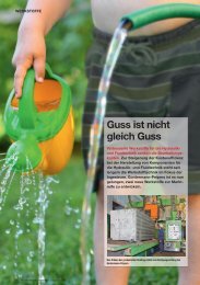
/12/ Gorski, R., Dörfer, F. : Guss ist nicht gleich Guss ,<br />
Konstruktion & Engineering Nov. 2009<br />
Machinability is improved substantially<br />
in comparison with the material GJS-<br />
<strong>500</strong>-7C. This leads to high cost savings<br />
when extensive cutting operations on<br />
hydraulic control blocks are involved.<br />
With the development of the material<br />
grade <strong>GOPAG®</strong> C <strong>500</strong> F by Gontermann-<br />
Peipers, it has become possible to use<br />
continuous cast iron for hydraulic control<br />
blocks with pressure stages of 350 to<br />
420 bar. Thus continuous castings made<br />
of <strong>GOPAG®</strong> C <strong>500</strong> F cast iron can be substituted<br />
for the forged steel used up until<br />
now for these high pressure stages.<br />
This material will become more important<br />
in the future due to the trend of<br />
alloying prices.<br />
<strong>GOPAG®</strong> C <strong>500</strong> F | QUALITY ASSESSMENT 8