GPS 1500 User Manual PN 2005906 Rev. C - GoodSoil
GPS 1500 User Manual PN 2005906 Rev. C - GoodSoil
GPS 1500 User Manual PN 2005906 Rev. C - GoodSoil

You also want an ePaper? Increase the reach of your titles
YUMPU automatically turns print PDFs into web optimized ePapers that Google loves.
<strong>GPS</strong> <strong>1500</strong> <strong>User</strong> <strong>Manual</strong><br />
<strong>PN</strong> <strong>2005906</strong> <strong>Rev</strong>. C
<strong>GPS</strong> <strong>1500</strong> <strong>User</strong> Guide<br />
Table of Contents<br />
Overview 1<br />
Introduction 2<br />
<strong>GPS</strong> Overview 3<br />
<strong>GPS</strong> Operation 3<br />
Automatic Tracking 3<br />
Receiver Performance 3<br />
Differential Operation 4<br />
SBAS 4<br />
WAAS and EGNOS explained 4<br />
Automatic SBAS tracking 4<br />
Setup 5<br />
Utility Setup Procedure 6<br />
Installation 12<br />
Installation 13<br />
Deutsch Connector Receptacle 13<br />
DB-9 Connection Tables 13<br />
DB-9 Connection for Cable 4001508-18 13<br />
HDB-15 Connection for Cable 4001509-18 14<br />
DB-9 Connection for Cable 4001510-18 14<br />
Cable Interface 15<br />
Extension Power/Data Cable 15<br />
When choosing a route for the <strong>GPS</strong> <strong>1500</strong> extension cable: 15<br />
Routing the Cable to the Cab 16<br />
Cable Part Numbers 16<br />
Mounting the <strong>GPS</strong> <strong>1500</strong> 17<br />
<strong>GPS</strong> <strong>1500</strong> Placement on Vehicle 17<br />
To place the <strong>GPS</strong> <strong>1500</strong> 17<br />
Radar Speed Output 18<br />
Radar Speed Compatibility 18<br />
Radar Speed Default Settings 18<br />
Radar Speed Adaptor Cables 18<br />
Connections to External Devices 19<br />
Factory parameters 19<br />
Troubleshooting 20<br />
LED Status Indicators 21<br />
Verifying Differential <strong>GPS</strong> Signal 21<br />
ii<br />
Part Number <strong>2005906</strong> <strong>Rev</strong> C
<strong>GPS</strong> <strong>1500</strong> <strong>User</strong> Guide<br />
Troubleshooting Table 22<br />
Appendix 23<br />
Specifications 24<br />
Power Specifications 24<br />
Mechanical Specifications 24<br />
Environmental Specifications 24<br />
<strong>GPS</strong> <strong>1500</strong> Accessories 25<br />
<strong>GPS</strong> <strong>1500</strong> 25<br />
<strong>GPS</strong> <strong>1500</strong> Documentation Accessories 25<br />
<strong>GPS</strong> <strong>1500</strong> Cable Accessories 25<br />
Company Warranty Statement 26<br />
Product Registration 29<br />
iii<br />
Part Number <strong>2005906</strong> <strong>Rev</strong> C
Overview<br />
OVERVIEW<br />
Introduction<br />
<strong>GPS</strong> Overview<br />
<strong>GPS</strong> Operation<br />
Differential Operation<br />
1<br />
Part Number <strong>2005906</strong> <strong>Rev</strong> C
<strong>GPS</strong> <strong>1500</strong> <strong>User</strong> Guide<br />
INTRODUCTION<br />
Congratulations on buying the Ag Leader <strong>GPS</strong> <strong>1500</strong>. The <strong>GPS</strong> <strong>1500</strong> is a smart<br />
antenna that tracks <strong>GPS</strong> and SBAS (WAAS and EGNOS) signals. This chapter provides<br />
information on the following:<br />
• “<strong>GPS</strong> Overview” on page 3<br />
• “<strong>GPS</strong> Operation” on page 3<br />
• “Differential Operation” on page 4<br />
2<br />
Part Number <strong>2005906</strong> <strong>Rev</strong> C
<strong>GPS</strong> <strong>1500</strong> <strong>User</strong> Guide<br />
<strong>GPS</strong> OVERVIEW<br />
This chapter describes the various modes of operation and features of your <strong>GPS</strong><br />
<strong>1500</strong> receiver and internal sensors.<br />
For your convenience, both the <strong>GPS</strong> and differential correction of the <strong>GPS</strong> <strong>1500</strong> are<br />
preconfigured. The receiver will work out of the box, and for most applications,<br />
little user set up is necessary. When powered for the first time, the <strong>GPS</strong> <strong>1500</strong> will<br />
perform a “cold start,” which involves acquiring the available <strong>GPS</strong> satellites in view<br />
and the SBAS differential service.<br />
<strong>GPS</strong> Operation<br />
The <strong>GPS</strong> engine is always operating, regardless of the D<strong>GPS</strong> mode of operation. The<br />
following sections describe the general operation of the <strong>GPS</strong> <strong>1500</strong> ’s internal <strong>GPS</strong><br />
engine.<br />
Automatic Tracking<br />
The <strong>GPS</strong> engine within the <strong>GPS</strong> <strong>1500</strong> automatically searches for <strong>GPS</strong> satellites,<br />
acquires the signals and manages the navigation information required for<br />
positioning and tracking.<br />
Receiver Performance<br />
The <strong>GPS</strong> <strong>1500</strong> works by finding four or more <strong>GPS</strong> satellites in the visible sky and uses<br />
the information those satellites provide to compute an appropriate position<br />
(typically within 2-3 meters). Since there is some error in the <strong>GPS</strong> data calculations,<br />
the <strong>GPS</strong> <strong>1500</strong> also tracks a differential correction. The <strong>GPS</strong> <strong>1500</strong> uses these<br />
corrections to improve its position to less than 1 meter (3 feet)<br />
There are two main aspects of <strong>GPS</strong> receiver performance:<br />
• Positioning<br />
• Satellite acquisition quality<br />
When the <strong>GPS</strong> <strong>1500</strong> is properly positioned on your vehicle, the satellites transmit<br />
coded information to the antenna in a specific frequency that allows the receiver to<br />
calculate a range to each satellite. <strong>GPS</strong> is essentially a timing system. The ranges are<br />
calculated by timing how long it takes for the <strong>GPS</strong> signal to reach the <strong>GPS</strong> antenna.<br />
The <strong>GPS</strong> receiver uses a complex algorithm incorporating satellite locations and<br />
ranges to each satellite to calculate the geographic location. Reception of any four<br />
or more of these signals allows a <strong>GPS</strong> receiver to compute three-dimensional<br />
coordinates.<br />
3<br />
Part Number <strong>2005906</strong> <strong>Rev</strong> C
Differential Operation<br />
<strong>GPS</strong> <strong>1500</strong> <strong>User</strong> Guide<br />
The Radio Technical Commission of Marine services (RTCM) has a differential service<br />
intended for correction services. This includes the Space Based Augmentation<br />
Systems (SBAS), such as the Wide Area Augmentation System (WAAS) and the<br />
European Geo-stationary Navigation Overlay System (EGNOS). The <strong>GPS</strong> <strong>1500</strong> is<br />
compatible with each of these differential services.<br />
SBAS<br />
A SBAS-enabled <strong>GPS</strong> <strong>1500</strong> operates automatically anywhere within the coverage<br />
areas of the WAAS, EGNOS or other SBAS programs.<br />
WAAS and EGNOS explained<br />
• WAAS is a free service of the Federal Aviation Administration (FAA) that<br />
allows regular <strong>GPS</strong> positions to be improved to a D<strong>GPS</strong> level of accuracy.<br />
WAAS is available everywhere in the U.S., including Alaska, Hawaii and<br />
Puerto Rico. It can also be picked up in some of the border areas of Mexico<br />
and Canada. There are no subscription charges incurred when using WAAS.<br />
• EGNOS is a similar service that is available in Europe and western Russia.<br />
Automatic SBAS tracking<br />
The <strong>GPS</strong> <strong>1500</strong> will automatically scan and track satellite signals. This automatic<br />
tracking allows you to focus on other aspects of differential operation without the<br />
need to tune the receiver. The <strong>GPS</strong> <strong>1500</strong> features two-channel SBAS tracking that<br />
provides an enhanced ability to maintain a lock on a SBAS satellite when more than<br />
one satellite is in view. This redundant tracking approach results in more consistent<br />
tracking of a SBAS signal when in an area where signal blockage of a satellite is<br />
possible.<br />
Note: For more information on Differential <strong>GPS</strong>,<br />
see “Verifying Differential <strong>GPS</strong> Signal” on page 21<br />
of the Troubleshooting chapter.<br />
4<br />
Part Number <strong>2005906</strong> <strong>Rev</strong> C
<strong>GPS</strong> <strong>1500</strong> <strong>User</strong> Guide<br />
SETUP<br />
Utility Setup Procedure<br />
5<br />
Part Number <strong>2005906</strong> <strong>Rev</strong> C
<strong>GPS</strong> <strong>1500</strong> <strong>User</strong> Guide<br />
UTILITY SETUP PROCEDURE<br />
The default <strong>GPS</strong> settings are 4800 baud, 1 Hz GGA and VTG NMEA strings. These<br />
settings will work for all Ag Leader products. However, if the equipment that you<br />
are using requires higher baud or Hertz rates, you many need to reconfigure the<br />
<strong>GPS</strong> using the following procedure.<br />
1. Download the Pocket Max PC.exe executable file from Ag Leader’sweb site:<br />
http://www.agleader.com/support.php?Page=downloads<br />
2. Double click on Pocket Max PC.exe.<br />
3. The Pocket Max PC program appears. On the Serial Port setting, select the correct<br />
COM Port that the <strong>GPS</strong> is connected to. Also, check the Auto Baud check box.<br />
Pocket PC with COM Port and Auto-Baud selected<br />
6<br />
Part Number <strong>2005906</strong> <strong>Rev</strong> C
<strong>GPS</strong> <strong>1500</strong> <strong>User</strong> Guide<br />
4. Press the Search button. The utility then searches for the correct <strong>GPS</strong> receiver.<br />
Utility after finding correct <strong>GPS</strong> receiver with OK button showing<br />
Note: If the utility cannot find the correct <strong>GPS</strong> receiver, use a<br />
different COM port and repeat. Also, make sure that the<br />
<strong>GPS</strong> is powered.<br />
5. Once the utility finds the correct <strong>GPS</strong> receiver, the OK button appears at the<br />
bottom of the window. Press the OK button.<br />
7<br />
Part Number <strong>2005906</strong> <strong>Rev</strong> C
<strong>GPS</strong> <strong>1500</strong> <strong>User</strong> Guide<br />
6. When the new window appears, click the Setup tab.<br />
7. Under the “This Port” column, (located on the left-hand side of the window) use<br />
the drop-down menu to select the correct Hz rate, such as 5 Hz.<br />
Selecting correct Hz rate on a NMEA string<br />
Note: Ag Leader’s products require the GGA and<br />
VTG NMEA strings. To find out the required NMEA<br />
strings for other products, check with the<br />
manufacturer.<br />
8<br />
Part Number <strong>2005906</strong> <strong>Rev</strong> C
<strong>GPS</strong> <strong>1500</strong> <strong>User</strong> Guide<br />
8. At the bottom of the drop-down menu, select the correct baud rate. These range<br />
between 4800 and 115,200.<br />
• Ag Leader’s PF series monitors require a 4800 baud rate.<br />
• Ag Leader’s InSightdisplays cannot use a baud rate higher than 38400.<br />
Selecting correct baud rate<br />
Note: At this time, the 57600 and 115200 baud<br />
rates are not supported. by Ag Leader monitors.<br />
9<br />
Part Number <strong>2005906</strong> <strong>Rev</strong> C
<strong>GPS</strong> <strong>1500</strong> <strong>User</strong> Guide<br />
9. When setup is complete, press on the Exit button, which is the red X located<br />
in the right-hand corner of the window.<br />
10. The Exit Options window appears, asking you to choose one of the following<br />
options. Always press Exit and Save.<br />
Exit Options window<br />
Note: If you choose a selection other than Exit and<br />
Save, your settings will not be saved.<br />
10<br />
Part Number <strong>2005906</strong> <strong>Rev</strong> C
<strong>GPS</strong> <strong>1500</strong> <strong>User</strong> Guide<br />
11. A series of messages appears, after which a Configuration Report will appear. At<br />
the configuration report, you can view your saved settings. However, you cannot<br />
make changes to these settings at this window<br />
New Receiver Configuration Report<br />
12. Press Close to end the utility program.<br />
11<br />
Part Number <strong>2005906</strong> <strong>Rev</strong> C
<strong>GPS</strong> <strong>1500</strong> <strong>User</strong> Guide<br />
INSTALLATION<br />
Cable Attachment Information<br />
Mounting the <strong>GPS</strong> <strong>1500</strong><br />
Powering the <strong>GPS</strong> <strong>1500</strong><br />
Connecting <strong>GPS</strong> <strong>1500</strong> to External Devices<br />
12<br />
Part Number <strong>2005906</strong> <strong>Rev</strong> C
<strong>GPS</strong> <strong>1500</strong> <strong>User</strong> Guide<br />
INSTALLATION<br />
The <strong>GPS</strong> <strong>1500</strong> is a smart antenna that tracks <strong>GPS</strong> and SBAS (WAAS and EGNOS).<br />
Deutsch Connector Receptacle<br />
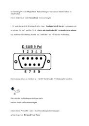
The picture below provides a front view of the Deutsch connector receptacle’s<br />
numbering.<br />
Deutsch connector receptacle numbering<br />
DB-9 Connection Tables<br />
DB-9 Connection for Cable 4001508-18<br />
Signal <strong>GPS</strong> Wire Color DB-9<br />
Deutsch<br />
Receptacle<br />
<strong>Manual</strong> Mark In 1 Violet 6<br />
TXB 2 White<br />
RXB 3 Gray<br />
Can High 4 Pink<br />
Signal Ground 5 Brown<br />
TXA 6 Green 3<br />
One PPS 7 Orange<br />
RXA 8 Blue 2<br />
Can Low 9 Tan<br />
Power In (12V) 10 Red 4<br />
Power Ground 11 Black 5 2 (Black)<br />
Speed Out 12 Yellow 1 (White)<br />
13<br />
Part Number <strong>2005906</strong> <strong>Rev</strong> C
<strong>GPS</strong> <strong>1500</strong> <strong>User</strong> Guide<br />
HDB-15 Connection for Cable 4001509-18<br />
Signal <strong>GPS</strong> Wire Color HDB 15<br />
Deutsch<br />
Receptacle<br />
<strong>Manual</strong> Mark In 1 Violet 5<br />
TXB 2 White<br />
RXB 3 Gray<br />
Can High 4 Pink<br />
Signal Ground 5 Brown<br />
TXA 6 Green 14<br />
One PPS 7 Orange<br />
RXA 8 Blue 13<br />
Can Low 9 Tan<br />
Power In (12V) 10 Red 10<br />
Power Ground 11 Black 11 2 (Black)<br />
Speed Out 12 Yellow 1 (White)<br />
DB-9 Connection for Cable 4001510-18<br />
Signal <strong>GPS</strong> Wire Color DB-9<br />
Deutsch<br />
Receptacle<br />
Cigarette Plug<br />
<strong>Manual</strong> Mark In 1 Violet<br />
TXB 2 White<br />
RXB 3 Gray<br />
Can High 4 Pink<br />
Signal Ground 5 Brown<br />
TXA 6 Green 2<br />
One PPS 7 Orange<br />
RXA 8 Blue 3<br />
Can Low 9 Tan<br />
Power In (12V) 10 Red 1 (White)<br />
Power Ground 11 Black 5 2 (Black) 2 (Black)<br />
Speed Out 12 Yellow 1 (White)<br />
14<br />
Part Number <strong>2005906</strong> <strong>Rev</strong> C
<strong>GPS</strong> <strong>1500</strong> <strong>User</strong> Guide<br />
CABLE INTERFACE<br />
The cable options include:<br />
• DB9 serial<br />
• Speed<br />
• Power<br />
Additional extension cables may be purchased, as necessary, for other installations.<br />
This allows the <strong>GPS</strong> <strong>1500</strong> to be quickly and easily moved from one installation to<br />
another. If an extension cable is damaged in the field, it can be replaced without<br />
returning the complete <strong>GPS</strong> <strong>1500</strong> system.<br />
Other power cables are available as accessories to fit a wide variety of applications.<br />
For a list of <strong>GPS</strong> <strong>1500</strong> accessories, see “<strong>GPS</strong> <strong>1500</strong> Accessories” on page 25.<br />
Extension Power/Data Cable<br />
The <strong>GPS</strong> <strong>1500</strong> system is quickly installed with one of the various extension cables.<br />
Keep in mind that the data connector communication port must reach to connect to<br />
a data storage device or guidance system.<br />
When choosing a route for the <strong>GPS</strong> <strong>1500</strong> extension cable:<br />
• Avoid running cables in areas of excessive heat.<br />
• Keep cables away from corrosive chemicals.<br />
• Keep the cables away from rotating machinery.<br />
• Do not bend excessively or crimp the cables.<br />
• Avoid placing tension on the cables.<br />
• Remove unwanted slack from the extension cable at the receiver end.<br />
• Secure along the cable route using plastic wraps.<br />
Improperly-installed cables near machinery can be<br />
dangerous.<br />
15<br />
Part Number <strong>2005906</strong> <strong>Rev</strong> C
<strong>GPS</strong> <strong>1500</strong> <strong>User</strong> Guide<br />
Routing the Cable to the Cab<br />
Follow these steps to route cable into the cab:<br />
1. Find a place on the right side or bottom of the cab to route cable into cab (the<br />
point of entry is up to you).<br />
Note: The cable can be routed through windows<br />
or doors but make sure that there will be no<br />
damage to the cable.<br />
2. Attach the <strong>GPS</strong> cable from the antenna to Port 1 of the PF3000, Port 1 on the YM<br />
2000, or the <strong>GPS</strong> port on the InSight display.<br />
• If you are attaching the <strong>GPS</strong><strong>1500</strong> to a PF Advantage or PF 3000 Pro without<br />
<strong>GPS</strong>, attach the <strong>GPS</strong> cable to AUX. 1 Port.<br />
• If you are connecting your <strong>GPS</strong><strong>1500</strong> to an alternative logging or mapping<br />
device (i.e. handheld or laptop computer), refer to your Operator's <strong>Manual</strong><br />
for that particular unit for correct cable connection.<br />
Cable Part Numbers<br />
See the following table for the appropriate cable for your installation.<br />
Display<br />
Cable Part Number<br />
InSight<br />
4001508-18<br />
PF 3000<br />
YM 2000<br />
PF Advantage 4001509-18<br />
Mobile Logging 4001510-18<br />
• Laptop<br />
• Handheld<br />
16<br />
Part Number <strong>2005906</strong> <strong>Rev</strong> C
<strong>GPS</strong> <strong>1500</strong> <strong>User</strong> Guide<br />
MOUNTING THE <strong>GPS</strong> <strong>1500</strong><br />
<strong>GPS</strong> <strong>1500</strong> Placement on Vehicle<br />
Placement of the <strong>GPS</strong> <strong>1500</strong> is crucial to the system’s operation. The <strong>GPS</strong> engine<br />
inside the <strong>GPS</strong> <strong>1500</strong> computes a position based upon measurements from each<br />
satellite to the internal <strong>GPS</strong> antenna unit. Mount the <strong>GPS</strong> <strong>1500</strong> on your point of<br />
interest. When choosing a location to mount the antenna, please make certain that<br />
there is an unobstructed view of the sky available to the <strong>GPS</strong> <strong>1500</strong> smart antenna.<br />
This will ensure that <strong>GPS</strong> satellites are not masked by obstructions, which can<br />
potentially reduce system performance.<br />
To place the <strong>GPS</strong> <strong>1500</strong><br />
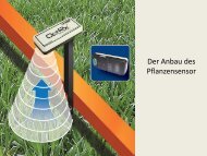
1. Mount the <strong>GPS</strong> <strong>1500</strong> on, or as close to, the center of your point of measurement.<br />
2. Position the <strong>GPS</strong> <strong>1500</strong> as high as possible.<br />
Below is an illustration of the ideal location to place the <strong>GPS</strong> <strong>1500</strong> on a vehicle.<br />
<strong>GPS</strong> <strong>1500</strong> placement on a vehicle<br />
17<br />
Part Number <strong>2005906</strong> <strong>Rev</strong> C
<strong>GPS</strong> <strong>1500</strong> <strong>User</strong> Guide<br />
RADAR SPEED OUTPUT<br />
The <strong>GPS</strong> <strong>1500</strong> is capable of outputting a simulated radar speed pulse. This simulates<br />
a similar pulse output that you would receive from a standard radar gun.<br />
To use the radar speed input you must set the speed input to RADAR under the<br />
appropriate setup screen for the monitor/display. Additional cables will also be<br />
required to obtain the simulated speed output. Contact Ag Leader’s Technical<br />
Support team for these additional cables.<br />
Radar Speed Compatibility<br />
Adaptor cables are available through Ag Leader Technology for the following three<br />
brands of monitors: Dickey-John, Raven, and Hiniker. These adaptor cables provide<br />
the ability to use the <strong>GPS</strong> <strong>1500</strong> in place of a radar gun. If using the <strong>GPS</strong> <strong>1500</strong> as a<br />
stand-alone antenna, you will need to obtain an Auxiliary Power/Data Cable and the<br />
appropriate Radar Speed Adaptor Cable.<br />
Radar Speed Default Settings<br />
The default output parameter provided in the <strong>GPS</strong> <strong>1500</strong> is a minimum output speed<br />
of .5 miles per hour (.8 kilometers per hour), meaning speed pulses will not be<br />
output below this speed. The default radar pulse output rate is 45 Hz per 1 MPH.<br />
Radar Speed Adaptor Cables<br />
Cable Name<br />
Part Number<br />
Hiniker adaptor cable 3000478<br />
Raven adaptor cable 3000479<br />
Dickey John adaptor cable 3000480<br />
18<br />
Part Number <strong>2005906</strong> <strong>Rev</strong> C
<strong>GPS</strong> <strong>1500</strong> <strong>User</strong> Guide<br />
CONNECTIONS TO EXTERNAL DEVICES<br />
The serial ports of the <strong>GPS</strong> <strong>1500</strong> operates at the RS-232C interface level to<br />
communicate with external data loggers, navigation systems and other devices. The<br />
serial ports are accessible via the extension cable that features a DB9 female data<br />
connector. The serial ports are also used for firmware updates.<br />
Note: For successful communication, the baud rate of the <strong>GPS</strong><br />
<strong>1500</strong> serial ports must be set to match that of the devices to<br />
which they are connected.<br />
The picture below displays the numbering for the extension cable’s DB-9 socket<br />
connector (female). The associated numbering for the plug connector (male) is a<br />
mirror reflection of the scheme shown below.<br />
Factory parameters<br />
Serial Port Settings<br />
DB-9 socket numbering<br />
This table identifies default settings for the <strong>GPS</strong> <strong>1500</strong> configuration.<br />
Serial Port<br />
Baud<br />
Rate<br />
Serial port A 4800<br />
9600<br />
38400<br />
57600<br />
Data<br />
Bits<br />
Parity<br />
Stop<br />
Bit<br />
Interface<br />
Levels<br />
Update<br />
Rate<br />
8 None 1 RS-232C 1 to 10 Hz<br />
19<br />
Part Number <strong>2005906</strong> <strong>Rev</strong> C
Troubleshooting<br />
TROUBLESHOOTING<br />
LED Status Indicators<br />
Verifying Differential <strong>GPS</strong> Signal<br />
Troubleshooting Table<br />
20<br />
Part Number <strong>2005906</strong> <strong>Rev</strong> C
LED Status Indicators<br />
The <strong>GPS</strong> <strong>1500</strong> uses one tri-colored LED, which indicates important status<br />
information.<br />
• Red indicates the power is on<br />
• Amber indicates a <strong>GPS</strong> lock<br />
• Flashing green indicates D<strong>GPS</strong> is being acquired<br />
• Green indicates a D<strong>GPS</strong> solution<br />
<strong>GPS</strong> <strong>1500</strong> <strong>User</strong> Guide<br />
Verifying Differential <strong>GPS</strong> Signal<br />
Differential <strong>GPS</strong> (D<strong>GPS</strong>) is a data collection technique that uses extra <strong>GPS</strong> receivers<br />
and some complex calculations to increase the accuracy of <strong>GPS</strong> positions. D<strong>GPS</strong> is<br />
made possible because of an enhancement to the Global Positioning System that<br />
uses a network of fixed, ground-based reference stations to broadcast the<br />
difference between the positions indicated by satellite systems and other known<br />
fixed positions.<br />
For more information on Differential <strong>GPS</strong>, see<br />
“Differential Operation” on page 4 of the<br />
Overview chapter.<br />
You should periodically check the monitor to ensure that you are receiving a<br />
Differential <strong>GPS</strong> signal, as this could affect the quality of the data you are logging.<br />
As an example, your <strong>GPS</strong> receiver must track four or more satellites to get an<br />
elevation reading.<br />
21<br />
Part Number <strong>2005906</strong> <strong>Rev</strong> C
<strong>GPS</strong> <strong>1500</strong> <strong>User</strong> Guide<br />
TROUBLESHOOTING TABLE<br />
The following table provides a checklist to troubleshoot common problems and<br />
their solutions for the <strong>GPS</strong> <strong>1500</strong>.<br />
Problem<br />
Possible solution<br />
Receiver fails<br />
to power<br />
No data from<br />
<strong>GPS</strong> <strong>1500</strong><br />
• Verify polarity of power leads<br />
• Check integrity of power cable connections<br />
• Check power input voltage<br />
(7 - 36 VDC)<br />
• Check current restrictions imposed by power source<br />
(maximum is 250 mA)<br />
• Check receiver power status (LED)<br />
• Check integrity and connectivity of power and data<br />
cable connections<br />
• The volume of data requested to be output by the<br />
<strong>GPS</strong> <strong>1500</strong> could be higher than what the current baud<br />
rate supports. Try using 4800, or higher, as the baud<br />
rate for all devices.<br />
No <strong>GPS</strong> lock • Check integrity of cable connections<br />
• Verify <strong>GPS</strong> <strong>1500</strong> ’s unobstructed view of the sky<br />
No SBAS lock • Check integrity of cable connections<br />
• Verify <strong>GPS</strong> <strong>1500</strong> ’s unobstructed view of the sky<br />
• Check SBAS visibility map<br />
22<br />
Part Number <strong>2005906</strong> <strong>Rev</strong> C
Appendix<br />
APPENDIX<br />
<strong>GPS</strong> <strong>1500</strong> Specifications<br />
<strong>GPS</strong> <strong>1500</strong> Accessories<br />
Warranty<br />
23<br />
Part Number <strong>2005906</strong> <strong>Rev</strong> C
<strong>GPS</strong> <strong>1500</strong> <strong>User</strong> Guide<br />
SPECIFICATIONS<br />
The following three tables provide the power, mechanical, communication,<br />
environmental and D<strong>GPS</strong> specifications for the <strong>GPS</strong> <strong>1500</strong>.<br />
Power Specifications<br />
Item<br />
Input voltage<br />
Power consumption<br />
Current Consumption<br />
Power connector<br />
Specification<br />
7 - 36 VDC<br />
< 2 W @ 12 VDC (typical)<br />
150 mA @ 12 VDC (typical)<br />
Cable mount environmentally sealed<br />
Mechanical Specifications<br />
Item<br />
Height<br />
Width<br />
Weight<br />
Mounting Options<br />
Specification<br />
54.7 mm (2.2in)<br />
129.5 mm (5.1 in)<br />
0.66 kg (1.45 lbs)<br />
Magnetic mount<br />
Environmental Specifications<br />
Item<br />
Specification<br />
Operating temperature<br />
Storage temperature<br />
Humidity 100%<br />
Enclosure<br />
Compliance<br />
-30° C to +70° C<br />
(-22° F to + 158° F)<br />
-40° C to +85° C<br />
(-40° F to + 185° F)<br />
Waterproof and dust proof<br />
FCC, CE<br />
Shock IEC 68-2-27<br />
Vibration ISO 16750-1<br />
EMI certification<br />
FCC part 15, E-Mark<br />
24<br />
Part Number <strong>2005906</strong> <strong>Rev</strong> C
<strong>GPS</strong> <strong>1500</strong> <strong>User</strong> Guide<br />
<strong>GPS</strong> <strong>1500</strong> ACCESSORIES<br />
The tables below provide the available accessories for the <strong>GPS</strong> <strong>1500</strong>.<br />
<strong>GPS</strong> <strong>1500</strong><br />
Ag LeaderPart<br />
Number<br />
Item<br />
4001372 <strong>GPS</strong> <strong>1500</strong> Receiver<br />
2000161 Antenna Bracket - L-shaped<br />
<strong>GPS</strong> <strong>1500</strong> Documentation Accessories<br />
Ag<br />
LeaderPart<br />
Number<br />
Documentation<br />
<strong>2005906</strong> <strong>GPS</strong> <strong>1500</strong> <strong>User</strong> <strong>Manual</strong><br />
2002868 Product Registration<br />
<strong>GPS</strong> <strong>1500</strong> Cable Accessories<br />
Ag Leader<br />
Part Number<br />
Cables<br />
4001508-18 Cable for YM 2000, PF 3000, and<br />
InSight display.<br />
4001509-18 Cable for PF Advantage.<br />
4001510-18 Cable for Cigarette Power/12V<br />
connector.<br />
For more information on cable attachments, see “Routing the Cable to the Cab” on<br />
page 16 in the Installation chapter.<br />
25<br />
Part Number <strong>2005906</strong> <strong>Rev</strong> C
<strong>GPS</strong> <strong>1500</strong> <strong>User</strong> Guide<br />
COMPANY WARRANTY STATEMENT<br />
WARRANTY<br />
Ag Leader Technology will repair or replace at no charge any component of the <strong>GPS</strong><br />
<strong>1500</strong> that fails during normal service, while being used in an approved application,<br />
within two years of the warranty start date. Warranty is not provided for damage<br />
resulting from abuse, neglect, accidents, vandalism, acts of nature, or any causes<br />
that are outside of the normal intended use of the <strong>GPS</strong> <strong>1500</strong>. Ag Leader Technology<br />
shall not be liable for indirect, incidental, or consequential damages to the dealer,<br />
end user, or third parties arising from the sale, installation, or use of any Ag Leader<br />
Technology product.<br />
COPYRIGHT NOTICE<br />
Ag Leader Technology has copyrighted (© 2007) the contents of this manual. No<br />
reproductions may be made without first obtaining the consent of Ag Leader<br />
Technology.<br />
SERVICE AND SUPPORT<br />
If you have additional questions or feel that you may be having a problem with your<br />
system, call your local Ag Leader Technology dealer or call us directly at the phone<br />
number below. If we determine you have a hardware failure, we will ship<br />
replacement hardware immediately.<br />
Our Technical Support Department can be reached by phone at 515-232-5363,<br />
extension #1; or through email at support@agleader.com.<br />
26<br />
Part Number <strong>2005906</strong> <strong>Rev</strong> C
Index<br />
Numerics<br />
12V connector cable 25<br />
A<br />
accessories 25<br />
automatic tracking 3<br />
B<br />
baud rate 22<br />
C<br />
cable<br />
data 15<br />
DB-9 connection 13<br />
Dickey John 18<br />
extension 15<br />
Hiniker 18<br />
Raven 18<br />
routing 16<br />
cable accessories 25<br />
cable interface 15<br />
cables<br />
improperly installed 15<br />
cigarette power<br />
cable 25<br />
D<br />
data cable 15<br />
data not coming from <strong>GPS</strong> <strong>1500</strong> 22<br />
DB-9 connection 13, 14<br />
mobile 14<br />
DB-9 socket 19<br />
DB-9 socket numbering 19<br />
Deutsch connector<br />
numbering 13<br />
D<strong>GPS</strong> 4<br />
verifying 21<br />
differential<br />
corrections 3<br />
differential <strong>GPS</strong> 4<br />
verifying 21<br />
Differential Operation 4<br />
E<br />
EGNOS 4<br />
environmental specifications 24<br />
extension cable 15<br />
choosing route 15<br />
Extension Power/Data Cable 15<br />
external device connections 19<br />
F<br />
factory parameters 19<br />
G<br />
<strong>GPS</strong><br />
no lock 22<br />
operation 3<br />
I<br />
input voltage 24<br />
InSight<br />
cable 25<br />
installation 12<br />
mounting 17<br />
L<br />
LED 21<br />
amber 21<br />
colors 21<br />
flashing green 21<br />
green 21<br />
red 21<br />
M<br />
mechanical specifications 24<br />
mounting 17<br />
O<br />
operating temperature 24<br />
P<br />
PF 3000<br />
cable 25<br />
27<br />
Part Number <strong>2005906</strong> <strong>Rev</strong> C
PF Advantage<br />
cable 25<br />
DB-9 connection 14<br />
positioning 3<br />
power cable connection 22<br />
power connector 24<br />
power consumption 24<br />
power input voltage 22<br />
power specifications 24<br />
Y<br />
YM 2000<br />
cable 25<br />
R<br />
radar pulse output rate 18<br />
radar speed adaptor cables 18<br />
radar speed compatibility 18<br />
radar speed default settings 18<br />
radar speed output 18<br />
receiver<br />
not powered 22<br />
receiver performance 3<br />
positioning 3<br />
satellite acquisition 3<br />
RS-232C 19<br />
S<br />
SBAS 4<br />
no lock 22<br />
tracking 4<br />
visibility map 22<br />
serial port settings 19<br />
setup 5<br />
specifications 24<br />
environmental 24<br />
mechanical 24<br />
power 24<br />
storage temperature 24<br />
T<br />
troubleshooting 22<br />
U<br />
utility setup 6<br />
W<br />
WAAS 4, 4<br />
warranty 26<br />
28<br />
Part Number <strong>2005906</strong> <strong>Rev</strong> C
<strong>GPS</strong> <strong>1500</strong> <strong>User</strong> Guide<br />
PRODUCT REGISTRATION<br />
Ag Leader Technology stands by all new products with a two-year limited warranty from the<br />
warranty start date. The warranty start date will initially be set to the date on which your<br />
product is shipped from Ag Leader Technology.<br />
If you return this registration/warranty card within 30 days of purchasing this product from your<br />
dealer, the warranty start date will be changed to the date that you purchased the product from<br />
your dealer. Ag Leader Technology reserves the right to request proof of the date of purchase<br />
stated.<br />
Timely product registration will allow you to receive important product bulletins, upgrade<br />
information, and notice regarding product training in your area.<br />
TO REGISTER:<br />
Register On-Line at www.agleader.com. Click on Product Registration from the Quick Links list<br />
on the Ag Leader Home Page.<br />
OR<br />
Return this sheet in the enclosed postage-paid envelope; or by FAX: 515-232-3595.<br />
Ag Leader Technology<br />
2202 South Riverside Drive<br />
P.O. Box 2348<br />
Ames, Iowa 50010<br />
Name:____________________________________________________________________________<br />
Street Address:_____________________________________________________________________<br />
City, State, ZIP: _____________________________________________________________________<br />
Phone # (including area code):________________________________________________________<br />
Mobile Phone #: ________________________ Fax #: ____________________________________<br />
Email address:______________________________________________________________________<br />
Ag Leader Dealer:___________________________________________________________________<br />
Date Purchased:_____________________________________________________________________<br />
<strong>GPS</strong> Antenna Serial #:________________________________________________________________<br />
29