

308922B 495st Airless Paint Sprayers - Graco Inc.
308922B 495st Airless Paint Sprayers - Graco Inc.
308922B 495st Airless Paint Sprayers - Graco Inc.

You also want an ePaper? Increase the reach of your titles
YUMPU automatically turns print PDFs into web optimized ePapers that Google loves.
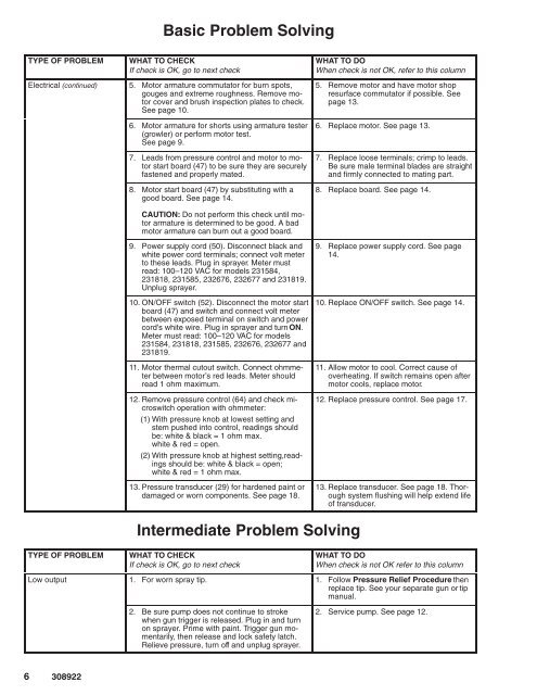
Basic Problem Solving<br />
TYPE OF PROBLEM<br />
WHAT TO CHECK<br />
If check is OK, go to next check<br />
Electrical (continued) 5. Motor armature commutator for burn spots,<br />
gouges and extreme roughness. Remove motor<br />
cover and brush inspection plates to check.<br />
See page 10.<br />
6. Motor armature for shorts using armature tester<br />
(growler) or perform motor test.<br />
See page 9.<br />
7. Leads from pressure control and motor to motor<br />
start board (47) to be sure they are securely<br />
fastened and properly mated.<br />
8. Motor start board (47) by substituting with a<br />
good board. See page 14.<br />
WHAT TO DO<br />
When check is not OK, refer to this column<br />
5. Remove motor and have motor shop<br />
resurface commutator if possible. See<br />
page 13.<br />
6. Replace motor. See page 13.<br />
7. Replace loose terminals; crimp to leads.<br />
Be sure male terminal blades are straight<br />
and firmly connected to mating part.<br />
8. Replace board. See page 14.<br />
CAUTION: Do not perform this check until motor<br />
armature is determined to be good. A bad<br />
motor armature can burn out a good board.<br />
9. Power supply cord (50). Disconnect black and<br />
white power cord terminals; connect volt meter<br />
to these leads. Plug in sprayer. Meter must<br />
read: 100–120 VAC for models 231584,<br />
231818, 231585, 232676, 232677 and 231819.<br />
Unplug sprayer.<br />
10. ON/OFF switch (52). Disconnect the motor start<br />
board (47) and switch and connect volt meter<br />
between exposed terminal on switch and power<br />
cord’s white wire. Plug in sprayer and turn ON.<br />
Meter must read: 100–120 VAC for models<br />
231584, 231818, 231585, 232676, 232677 and<br />
231819.<br />
11. Motor thermal cutout switch. Connect ohmmeter<br />
between motor’s red leads. Meter should<br />
read 1 ohm maximum.<br />
12. Remove pressure control (64) and check microswitch<br />
operation with ohmmeter:<br />
(1) With pressure knob at lowest setting and<br />
stem pushed into control, readings should<br />
be: white & black = 1 ohm max.<br />
white & red = open.<br />
(2) With pressure knob at highest setting,readings<br />
should be: white & black = open;<br />
white & red = 1 ohm max.<br />
13. Pressure transducer (29) for hardened paint or<br />
damaged or worn components. See page 18.<br />
9. Replace power supply cord. See page<br />
14.<br />
10. Replace ON/OFF switch. See page 14.<br />
11. Allow motor to cool. Correct cause of<br />
overheating. If switch remains open after<br />
motor cools, replace motor.<br />
12. Replace pressure control. See page 17.<br />
13. Replace transducer. See page 18. Thorough<br />
system flushing will help extend life<br />
of transducer.<br />
TYPE OF PROBLEM<br />
Intermediate Problem Solving<br />
WHAT TO CHECK<br />
If check is OK, go to next check<br />
WHAT TO DO<br />
When check is not OK refer to this column<br />
Low output 1. For worn spray tip. 1. Follow Pressure Relief Procedure then<br />
replace tip. See your separate gun or tip<br />
manual.<br />
2. Be sure pump does not continue to stroke<br />
when gun trigger is released. Plug in and turn<br />
on sprayer. Prime with paint. Trigger gun momentarily,<br />
then release and lock safety latch.<br />
Relieve pressure, turn off and unplug sprayer.<br />
2. Service pump. See page 12.


