


Create successful ePaper yourself
Turn your PDF publications into a flip-book with our unique Google optimized e-Paper software.
INSTRUCTIONS–PARTS LIST<br />
<strong>824128</strong><br />
Rev. G<br />
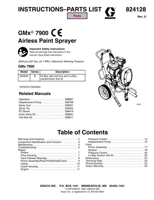
GMx 7900<br />
Airless Paint Sprayer<br />
Important Safety Instructions<br />
Read all warnings and instructions in this<br />
manual. Save these instructions.<br />
3300 psi (227 bar, 22.7 MPa ) Maximum Working Pressure<br />
GMx 7900<br />
Model Series Description<br />
824630 B Hi-Boy with tool box and Lo-Boy<br />
suction/drain line kit<br />
PATENTS PENDING<br />
Related Manuals<br />
Operation . . . . . . . . . . . . . . . . . . . . . . . . . . 308867<br />
Displacement Pump . . . . . . . . . . . . . . . . . 308798<br />
Spray Gun . . . . . . . . . . . . . . . . . . . . . . . . . 309091<br />
Spray Tip . . . . . . . . . . . . . . . . . . . . . . . . . . . 309055<br />
PC Board . . . . . . . . . . . . . . . . . . . . . . . . . . 308919<br />
Drain Valve Kit . . . . . . . . . . . . . . . . . . . . . . 308961<br />
Tool Box Kit . . . . . . . . . . . . . . . . . . . . . . . . 308817<br />
9035B<br />
Table of Contents<br />
Warnings and Cautions . . . . . . . . . . . . . . . . . . . . . . . . . 2 Pressure Control . . . . . . . . . . . . . . . . . . . . . . . . . . . . 13<br />
Component Identification and Function . . . . . . . . . . . . 3 Displacement Pump . . . . . . . . . . . . . . . . . . . . . . . . . 15<br />
Maintenance . . . . . . . . . . . . . . . . . . . . . . . . . . . . . . . . . . . 4 Parts<br />
Troubleshooting . . . . . . . . . . . . . . . . . . . . . . . . . . . . . . . . 5 Pinion Assembly . . . . . . . . . . . . . . . . . . . . . . . . . . . . 17<br />
Repair<br />
Sprayer . . . . . . . . . . . . . . . . . . . . . . . . . . . . . . . . . . . . 18<br />
Rollers . . . . . . . . . . . . . . . . . . . . . . . . . . . . . . . . . . . . . . 7 Pressure Control . . . . . . . . . . . . . . . . . . . . . . . . . . . . 20<br />
Drive Housing . . . . . . . . . . . . . . . . . . . . . . . . . . . . . . . . 7 Lo-Boy Suction Set Kit . . . . . . . . . . . . . . . . . . . . . . . 22<br />
Cam Follower Bearings . . . . . . . . . . . . . . . . . . . . . . . 8 Dimensions . . . . . . . . . . . . . . . . . . . . . . . . . . . . . . . . . . . 23<br />
Pinion Assembly/Rotor/Field/Shaft/Clutch . . . . . . . . 9 Technical Data . . . . . . . . . . . . . . . . . . . . . . . . . . . . . . . . 23<br />
Clamp . . . . . . . . . . . . . . . . . . . . . . . . . . . . . . . . . . . . . 10 Phone Number . . . . . . . . . . . . . . . . . . . . . . . . . . . . . . . . 23<br />
Clutch Housing . . . . . . . . . . . . . . . . . . . . . . . . . . . . . . 11 <strong>Graco</strong> Warranty . . . . . . . . . . . . . . . . . . . . . . . . . . . . . . . 24<br />
Engine . . . . . . . . . . . . . . . . . . . . . . . . . . . . . . . . . . . . . 11<br />
GRACO INC. P.O. BOX 1441 MINNEAPOLIS, MN 55440–1441<br />
COPYRIGHT 1999, GRACO INC.<br />
<strong>Graco</strong> <strong>Inc</strong>. is registered to I.S. EN ISO 9001
Warnings and Cautions<br />
Warning Symbol<br />
WARNING<br />
This symbol alerts you to the possibility of serious<br />
injury or death if you do not follow the instructions.<br />
Caution Symbol<br />
CAUTION<br />
This symbol alerts you to the possibility of damage to<br />
or destruction of equipment if you do not follow the<br />
instructions.<br />
WARNING<br />
Fire and explosion can occur when spraying or flushing flammable<br />
fluid in an area where air circulation is poor and flammable vapors<br />
can be ignited by an open flame or sparks.<br />
To help prevent a fire and explosion:<br />
Use outdoors or in an extremely well ventilated area.<br />
Do not use 1,1,1–trichloroethane, methylene chloride, other<br />
halogenated hydrocarbon solvents or fluids containing such<br />
solvents in pressurized aluminum equipment. Such use could<br />
result in a chemical reaction, with the possibility of explosion.<br />
Remove, extinguish or unplug all ignition sources;<br />
tape wall switch. Do not smoke in spray area.<br />
Never fill fuel tank while the engine is running or hot.<br />
Ground Sprayer, object being sprayed, paint and solvent pails.<br />
Hold gun firmly to side of a grounded pail when triggering into pail.<br />
Use only conductive airless paint hose.<br />
Never run engine in inclosed area.<br />
Fluid injection is a serious injury! If high pressure fluid pierces<br />
your skin, the injury might look like “just a cut”. But it is a serious<br />
wound! Get immediate surgical attention.<br />
To help prevent injection, always:<br />
Engage trigger safety latch when not spraying.<br />
Point gun away from yourself or anyone else.<br />
Relieve pressure before checking or repairing any leak.<br />
Relieve pressure when you turn off the sprayer or stop spraying.<br />
Do not use components rated less than system Maximum<br />
Working Pressure<br />
Never allow children to use this unit. If you are injured using this<br />
equipment, get immediate surgical treatment.<br />
2<br />
<strong>824128</strong>
Component Identification and Function<br />
V<br />
D<br />
C<br />
J<br />
H<br />
E<br />
R<br />
G<br />
K<br />
P<br />
S<br />
F<br />
A<br />
B<br />
U<br />
W<br />
T<br />
Model 824630<br />
Fig. 1<br />
M<br />
X<br />
N<br />
L<br />
9034B<br />
A Pressure Control Switch ON/OFF, enables/disables clutch function and pressure control<br />
B Pressure Adjusting Knob Controls fluid outlet pressure<br />
C Air Cleaner* Filters air entering the carburetor<br />
D Fuel Tank* Uses 86 octane unleaded gasoline<br />
E Muffler* Reduces noise of internal combustion<br />
F Spark Plug Cable* Routes electrical current to spark plug<br />
G Fuel Shutoff Lever* On/off lever to regulate fuel flow from gasoline tank to carburetor<br />
H Choke* Enriches air/gasoline mixture for cold starting<br />
J Throttle Lever* Adjusts engine speed for large or small orifice spray tips<br />
K Engine Switch* Enables/disables engine operation<br />
L Secondary Fluid Outlet Second hose and spray gun is connected here<br />
M Pressure Control Controls clutch cycling to maintain fluid pressure.<br />
N Primary Fluid Outlet Hose and spray gun is connected here<br />
P Engine* 4–cycle gasoline engine<br />
R Clutch Housing Transfers power from engine to drive assembly<br />
S Drive Housing Transfers power from clutch to displacement pump<br />
T Displacement Pump Provides fluid to be sprayed through spray gun<br />
U Fluid Filter Filters fluid between source and spray gun<br />
V Grounding Clamp and Wire Grounds sprayer system<br />
W Pail Hanger Provides a hanger for paint pail<br />
X Drain Valve Relieves fluid pressure when open<br />
* For more detailed explanations of these controls, refer to the Honda Engines Owner’s Manual; supplied<br />
<strong>824128</strong> 3
Maintenance<br />
WARNING<br />
INJECTION HAZARD<br />
The system pressure must be manually<br />
relieved to prevent the system from<br />
starting or spraying accidentally. Fluid<br />
under high pressure can be injected through the<br />
skin and cause serious injury. To reduce the risk of<br />
an injury from injection, splashing fluid, or moving<br />
parts, follow the Pressure Relief Procedure<br />
whenever you:<br />
are instructed to relieve the pressure,<br />
stop spraying,<br />
check or service any of the system equipment,<br />
or install or clean the spray tip.<br />
Pressure Relief Procedure<br />
1. Lock gun trigger safety.<br />
2. Turn engine ON/OFF switch to OFF.<br />
3. Move pressure control switch to OFF and turn<br />
pressure control knob fully counterclockwise.<br />
4. Unlock trigger safety. Hold metal part of gun firmly<br />
to side of grounded metal pail, and trigger gun to<br />
relieve pressure.<br />
5. Lock gun trigger safety.<br />
6. Open pressure drain valve. Leave valve open until<br />
ready to spray again.<br />
If you suspect that the spray tip or hose is completely<br />
clogged, or that pressure has not been fully relieved<br />
after following the steps above, VERY SLOWLY<br />
loosen tip guard retaining nut or hose end coupling to<br />
relieve pressure gradually, then loosen completely.<br />
Now clear tip or hose.<br />
CAUTION<br />
For detailed engine maintenance and specifications,<br />
refer to separate Honda Engines Owner’s Manual,<br />
supplied.<br />
DAILY:<br />
DAILY:<br />
DAILY:<br />
Check pressure drain valve for proper opera-<br />
DAILY:<br />
tion.<br />
DAILY:<br />
Check engine oil level and fill as necessary.<br />
Check hose for wear and damage.<br />
Check gun safety for proper operation.<br />
Check and fill the gas tank.<br />
AFTER THE FIRST 20 HOURS OF OPERATION:<br />
Drain engine oil and refill with clean oil. Reference<br />
Honda Engines Owner’s Manual for correct oil viscosity.<br />
WEEKLY: Remove air filter cover and clean element.<br />
Replace element, if necessary. If operating in an<br />
unusually dusty environment: check filter daily and<br />
replace, if necessary.<br />
Replacement elements can be purchased from your<br />
local HONDA dealer.<br />
WEEKLY: Check level of TSL in displacement pump<br />
packing nut. Fill nut, if necessary. Keep TSL in nut to<br />
help prevent fluid buildup on piston rod and premature<br />
wear of packings.<br />
AFTER EACH 100 HOURS OF OPERATION:<br />
Change engine oil. Reference Honda Engines Owner’s<br />
Manual for correct oil viscosity.<br />
SPARK PLUG: Use only BPR6ES (NGK) or<br />
W20EPR–U (NIPPONDENSO) plug. Gap plug to<br />
0.028 to 0.031 in. (0.7 to 0.8 mm). Use spark plug<br />
wrench when installing and removing plug.<br />
4<br />
<strong>824128</strong>
WARNING<br />
Troubleshooting<br />
INJECTION HAZARD<br />
To reduce risk of serious injury, including fluid injection or splashing in eyes or on skin, or injury from<br />
moving parts, always follow Pressure Relief Procedure Warning, page 4, before checking, adjusting,<br />
cleaning or shutting down sprayer.<br />
PROBLEM CAUSE SOLUTION<br />
Engine won’t start Engine switch is OFF Turn engine switch ON<br />
Engine is out of gas<br />
Engine oil level is low<br />
Spark plug cable is disconnected or damaged<br />
Cold engine<br />
Fuel shutoff lever is OFF<br />
Refill gas tank. Honda Engines Owner’s Manual.<br />
Try to start engine. Replenish oil, if necessary.<br />
Honda Engines Owner’s Manual.<br />
Connect spark plug cable or replace spark<br />
plug<br />
Use choke<br />
Move lever to ON position<br />
Oil is seeping into combustion chamber Remove spark plug. Pull starter rope 3 or 4<br />
times. Clean or replace spark plug. Try to start<br />
engine. Keep sprayer upright to avoid oil seepage.<br />
Engine operates, but dis-<br />
Pressure control switch is OFF<br />
Turn pressure control switch ON.<br />
placement pump does not<br />
operate Pressure setting is too low Turn pressure adjusting knob clockwise to<br />
increase pressure.<br />
Fluid filter (318) is dirty Clean filter. Page 20.<br />
Tip or tip filter is clogged Clean tip or tip filter. Manual 309091.<br />
Displacement pump piston rod is stuck due to<br />
dried paint<br />
Repair pump. Manual 308798.<br />
Roller bearings are worn or damaged Replace connecting rod. Page 7.<br />
Drive housing is worn or damaged Replace drive housing. Page 7.<br />
Electrical power is not energizing clutch field Check wiring connections. Page 11.<br />
Reference control board diagnostics. Page 14.<br />
With pressure control switch ON and pressure<br />
turned to MAXIMUM, use a test light to check<br />
for power between clutch terminals on control<br />
board.<br />
Remove black clutch wires from control board<br />
and measure resistance across wires. At 70<br />
F, the resistance must be between 1.7 ±0.2Ω; if<br />
not, replace clutch coil 241121.<br />
Have pressure control checked by authorized<br />
<strong>Graco</strong> dealer.<br />
Clutch is worn or damaged Replace clutch. Page 9.<br />
Pinion assembly is worn or damaged Repair or replace pinion assembly. Page 9.<br />
<strong>824128</strong> 5
PROBLEM CAUSE SOLUTION<br />
Pump output is low Strainer (31) is clogged Clean strainer<br />
Piston ball (25) is not seating Service piston ball. Manual 308798.<br />
Piston packings are worn or damaged Replace packings. Manual 308798.<br />
O-ring (227) in displacement pump is worn or<br />
damaged<br />
Replace o-ring. Manual 308798.<br />
Intake valve ball is not seating properly Clean intake valve. manual 308798.<br />
Engine speed is too low <strong>Inc</strong>rease throttle setting. Manual 308867.<br />
Clutch is worn or damaged Replace clutch. Page 9.<br />
Pressure setting is too low <strong>Inc</strong>rease pressure. Manual 308867.<br />
Excessive paint leakage into<br />
throat packing nut<br />
Fluid filter (318), tip filter or tip is clogged or<br />
dirty<br />
Large pressure drop in hose with heavy<br />
materials<br />
Throat packing nut is loose<br />
Clean filter. Manual 308867 or 309091.<br />
Use larger diameter hose and/or reduce overall<br />
length of hose. Use of more than 100 ft of 1/4<br />
in. hose significantly reduces performance of<br />
sprayer. Use 3/8 in. hose for optimum performance<br />
(50 ft minimum).<br />
Remove throat packing nut spacer. Tighten<br />
throat packing nut just enough to stop leakage.<br />
Throat packings are worn or damaged Replace packings. Manual 308798.<br />
Displacement rod is worn or damaged Replace rod. Manual 308798.<br />
Fluid is spitting from gun Air in pump or hose Check and tighten all fluid connections.<br />
Reprime pump. Manual 308867.<br />
Tip is partially clogged Clear tip. Manual 309091.<br />
Fluid supply is low or empty<br />
Refill fluid supply. Prime pump. Manual<br />
308867. Check fluid supply often to prevent<br />
running pump dry.<br />
Pump is difficult to prime Air in pump or hose Check and tighten all fluid connections.<br />
Reduce engine speed and cycle pump as<br />
slowly as possible during priming.<br />
Intake valve is leaking<br />
Clean intake valve. Be sure ball seat is not<br />
nicked or worn and that ball seats well. Reassemble<br />
valve.<br />
Pump packings are worn Replace pump packings. Manual 308798.<br />
Clutch squeaks each time<br />
clutch engages<br />
Paint is too thick<br />
Engine speed is too high<br />
Clutch surfaces are not matched to each other<br />
when new and may cause noise<br />
Thin the paint according to the supplier’s<br />
recommendations<br />
Decrease throttle setting before priming pump.<br />
Manual 308867.<br />
Clutch surfaces need to wear into each other.<br />
Noise will dissipate after a day of run time<br />
Engine stalls Engine speed is to slow <strong>Inc</strong>rease throttle setting<br />
Adjust engine speed at no load to 3750 –<br />
3850 rpm<br />
Fluid filter is clogged<br />
Too much pump friction (new pump)<br />
Spark plug wire is loose<br />
Relieve pressure and clean filter<br />
Reduce pressure to 3000 psi until pump wears<br />
in<br />
Reconnect wire<br />
6<br />
<strong>824128</strong>
Rollers<br />
Removal<br />
20<br />
1.<br />
Relieve pressure; page 4.<br />
98<br />
2. Fig. 2. Remove six cap screws (10) lock washers<br />
(9) and cover assembly (24).<br />
97<br />
9<br />
10<br />
Note: A screw driver may be needed to pry off<br />
cover assembly.<br />
3. Remove dowel pins (97) and rollers (98)<br />
Installation<br />
1. Install rollers (98) and dowel pins (97)<br />
2. Install cover assembly (24) with six lock washers<br />
(9) and cap screws (10). Fig. 2<br />
Drive Housing<br />
9<br />
99<br />
24<br />
9033A<br />
Removal<br />
1.<br />
Relieve pressure; page 4.<br />
2. Fig. 2. Remove six cap screws (10) lock washers<br />
(9) and cover assembly (24).<br />
3. Fig. 3. Remove two screws (99) and washers (9).<br />
4. Remove four cap screws (10) lock washers (9)<br />
from drive housing (20).<br />
5. Lightly tap around drive housing (20) to loosen<br />
drive housing. Pull drive housing straight off pinion<br />
housing. Be prepared to support gear cluster (18),<br />
which may also come out.<br />
10<br />
9<br />
1<br />
20h<br />
20g<br />
18<br />
20<br />
Installation<br />
1. Liberally apply bearing grease (supplied with<br />
replacement gear cluster) to gear cluster (18),<br />
washers (82) and (83) and to areas called out by<br />
note 1. Use full 0.68 pint (0.32 liter) of grease for<br />
GMx 7900.<br />
2. Place bronze colored washer (83) and silver<br />
colored washer (82) onto drive housing (20). Install<br />
gear cluster (18) through washers (83) and (82).<br />
3. Place bronze colored washer (20g) and silver<br />
colored washer (20h) on shaft protruding from<br />
large shaft of drive housing (20). Align gears and<br />
push new drive housing straight onto pinion housing<br />
and locating pins (B).<br />
4. Install two washers (9) and screws (99).<br />
5. Install four lock washers (9) and cap screws (10)<br />
into drive housing (20).<br />
6. Install cover assembly (24) with six lock washers<br />
(9) and cap screws (10).<br />
B<br />
82<br />
83<br />
9<br />
99<br />
1 Apply remaining grease to these areas<br />
Fig. 3<br />
9032A<br />
<strong>824128</strong> 7
Cam Follower Bearings<br />
Removal<br />
1.<br />
Relieve pressure; page 4.<br />
Installation<br />
1. Install two cam follower bearings (20c).<br />
2. Fig. 16. Cycle pump piston rod (222) to lowest<br />
position. Turn engine off.<br />
3. Fig. 4. Remove six cap screws (10), lock washers<br />
(9) and cover assembly (24).<br />
Note: A screw driver may be needed to pry off<br />
cover assembly.<br />
4. Remove four dowel pins (97) and rollers (98).<br />
5. From front, drive out pump pin (101) with a screw<br />
driver.<br />
6. Remove two retainer rings (20d).<br />
7. Remove cam follower plate (20b).<br />
Note: Two 1/2 in. x 13 bolts may be<br />
needed to remove cam follower plates.<br />
8. Remove two cam follower bearings (20c).<br />
2. Install cam follower plate (20b).<br />
3. Install two retainer rings (20d).<br />
4. Drive in pump pin (101) until it engages with pump<br />
pin retaining clip (20a).<br />
5. Install four rollers (98) and dowel<br />
pins (97).<br />
6. Install cover assembly (24) with six lock washers<br />
(9) and cap screws (10).<br />
20<br />
98<br />
97<br />
9<br />
10<br />
20a<br />
20c<br />
20b<br />
20d<br />
101<br />
9047A<br />
Fig. 4<br />
24<br />
8<br />
<strong>824128</strong>
Pinion Assembly/Rotor/Field/Shaft/Clutch<br />
Removal<br />
If pinion assembly (19) is not removed from clutch<br />
housing (5), do 1. through 4. Otherwise, start at 5.<br />
6. Fig. 8. Remove retaining ring (19e).<br />
7. Tap pinion shaft (19d) out with plastic mallet.<br />
1.<br />
Relieve pressure; page 4.<br />
19e<br />
2. Disconnect field cable (X) from pressure control<br />
and engine lead.<br />
19d<br />
X<br />
Fig. 8<br />
9030A<br />
Fig. 5<br />
Bottom View<br />
9027A<br />
3. Fig. 6. Remove five screws (26) and lockwashers<br />
(17) and pinion assembly (19).<br />
8. Fig.9. Use an impact wrench or wedge something<br />
between armature (4a) and clutch housing to hold<br />
engine shaft during removal.<br />
9. Remove four screws (16) and lockwashers (17).<br />
10. Remove armature (4a).<br />
26<br />
17<br />
19<br />
4a<br />
17<br />
16<br />
Fig. 9<br />
9028A<br />
Fig. 6<br />
26<br />
17<br />
9029A<br />
4. Fig. 7. Place pinion assembly (19) on bench with<br />
rotor side up.<br />
5. Remove four screws (72) and lockwashers (17).<br />
Install two screws in threaded holes (E) in rotor.<br />
Alternately tighten screws until rotor comes off.<br />
E<br />
72<br />
17<br />
Fig. 7<br />
9030A<br />
<strong>824128</strong> 9
Pinion Assembly/Rotor/Field/Shaft/Clutch<br />
Installation<br />
1. Fig. 10. Lay two stacks of two dimes on smooth<br />
bench surface.<br />
2. Lay armature (4a) on two stacks of dimes.<br />
6. Fig. 8. Tap pinion shaft (19d) in with plastic mallet.<br />
7. Install retaining ring (19e) with beveled side facing<br />
field (Y).<br />
3. Press center of clutch down on bench surface.<br />
4a<br />
Fig. 10<br />
0.12 ±.01 in. (3.0 ±.25 mm)<br />
4. Install armature (4a) on engine drive shaft.<br />
8705A<br />
8. Fig. 7. Place pinion assembly on bench with rotor<br />
side up.<br />
9. Apply locktite to screws. Install four screws (16)<br />
and lockwashers (17). Alternately torque screws<br />
to 125 in-lb until rotor is secure. Use threaded<br />
holes to hold rotor.<br />
10. Fig. 6. Install pinion assembly (19) with five screws<br />
(10) and lockwashers (9).<br />
5. Install four screws (16) and lockwashers (17) with<br />
torque of 125 in-lb.<br />
11. Fig. 5. Connect field cable (X) to pressure control<br />
and engine lead.<br />
Clamp<br />
Removal<br />
1. Fig. 11. Loosen two screws (16) on clamp (8),<br />
1<br />
2<br />
Face of clutch housing<br />
1.812 ±.010 in. (46.02 ±.25 mm)<br />
2. Push screwdriver into slot in clamp (8) and remove<br />
clamp.<br />
3<br />
Torque to 125 ±.10 in-lb (14 ±1.1 Nm)<br />
4 Chamfer this side<br />
Installation<br />
1<br />
5<br />
1. Fig. 11. Install engine shaft key (7).<br />
2. Tap clamp (8) on engine shaft (A) with plastic<br />
mallet.<br />
2<br />
8<br />
3. Press clamp (8) onto engine shaft (A). Maintain<br />
dimension shown note 2 in Fig. 11. Chamfer side<br />
must face engine.<br />
7<br />
B<br />
4<br />
Check dimension: Place rigid, straight steel bar (B)<br />
across face of clutch housing (5). Use accurate<br />
measuring device to measure distance between<br />
bar and face of clamp. Adjust clamp as necessary.<br />
Torque two screws (16) to 125 ±10 in-lb (14 ±1.1<br />
Nm). Fig. 11<br />
A<br />
16 3<br />
03483<br />
10<br />
<strong>824128</strong>
Removal<br />
1. Fig. 12. Remove four capscrews (75) and lockwashers<br />
(77) which hold clutch housing (5) to<br />
engine.<br />
2. Remove screw (15) from under mounting plate (D).<br />
3. Remove engine key (7).<br />
4. Pull off clutch housing (5).<br />
Clutch Housing<br />
7<br />
5<br />
Installation<br />
1. Fig. 12. Push on clutch housing (5).<br />
2. Install four capscrews (75) and lockwashers (77)<br />
and secure clutch housing (5) to engine. Torque to<br />
200 in-lb (22.6 Nm).<br />
3. Install capscrew (15) from beneath mounting<br />
plate (D). Torque to 26 ft-lb (35.2 Nm).<br />
Removal<br />
Fig. 12<br />
Engine<br />
15<br />
D<br />
77<br />
75<br />
89025A<br />
1. Remove Pinion Assembly/Rotor/Field/Pinion/<br />
Clutch, Clamp and Clutch Housing, as instructed<br />
on pages 7, 9 and 10.<br />
2. Fig. 13. Disconnect all necessary wiring.<br />
3. Fig. 14. Remove two locknuts (71) and screws<br />
(70) from base of engine.<br />
4. Lift engine carefully and place on work bench.<br />
NOTE: All service to the engine must be performed by<br />
an authorized HONDA dealer.<br />
70<br />
87<br />
Green<br />
71<br />
71<br />
1<br />
Fig. 14<br />
Installation<br />
1. Lift engine carefully and place on cart.<br />
9026A<br />
2<br />
2. Fig. 14. Install two screws (70) in base of engine<br />
and secure with locknuts (71). Torque to 200 in-lb<br />
(22.6 Nm).<br />
Fig. 13<br />
2<br />
1<br />
2<br />
To the field<br />
To the engine<br />
9027A<br />
3. Fig. 13. Connect all necessary wiring.<br />
4. Install Pinion Assembly/Rotor/Field/Pinion/<br />
Clutch, Clamp and Clutch Housing, as<br />
instructed on pages 7, 9 and 10.<br />
<strong>824128</strong> 11
On/Off Switch<br />
Removal<br />
1.<br />
Relieve pressure; page 4.<br />
2. Fig. 15. Remove five screws (307) and<br />
cover (322).<br />
3. Disconnect two wires (A) from ON/OFF<br />
switch (309).<br />
4. Press in on two retaining tabs on each side of<br />
ON/OFF switch (309) and remove switch.<br />
Installation<br />
1. Install new ON/OFF switch (309) so tabs of switch<br />
snap into place on inside of pressure control<br />
housing.<br />
2. Connect two wires (A) to ON/OFF switch.<br />
3. Install pressure control cover (322) with five<br />
screws (307).<br />
1<br />
313<br />
310<br />
309<br />
A<br />
315 319<br />
318a<br />
307<br />
302<br />
303<br />
322<br />
D<br />
318z<br />
318aa<br />
Fig. 15<br />
E<br />
1 Locate switch terminals as shown<br />
8711A<br />
12<br />
<strong>824128</strong>
Pressure Control<br />
Control Board<br />
Removal<br />
1.<br />
Relieve pressure; page 4.<br />
Installation<br />
When installing replacement control board, follow<br />
instructions with control board to set model type.<br />
2. Fig. 15. Remove five screws (307) and<br />
cover (322).<br />
3. Fig. 22. Disconnect at control board (302):<br />
Four clutch leads: two violet and two black.<br />
Lead (D) from potentiometer.<br />
Lead (E) from transducer.<br />
Two red leads (A) to ON/OFF switch (309).<br />
4. Fig. 15. Remove five screws (303), green ground<br />
wire and control board (302).<br />
1. Fig. 15. Install green ground wire and control<br />
board (302) with five screws (303).<br />
2. Fig. 22. Connect to control board (302):<br />
Two red leads (A) to ON/OFF switch (309).<br />
Lead (E) to transducer.<br />
Lead (D) to potentiometer.<br />
Four clutch leads: two violet and two black.<br />
3. Fig. 15. Install cover (322) with five screws (307).<br />
Pressure Control Transducer<br />
Removal<br />
1.<br />
Relieve pressure; page 4.<br />
2. Fig. 15. Remove five screws (307) and<br />
cover (322).<br />
3. Disconnect lead (E) from control board (302).<br />
4. Remove three screws (319) and fluid filter (318)<br />
from control plate (301). Carefully pull transducer<br />
connector through rubber grommet (315).<br />
5. Remove pressure control transducer (318z) and<br />
packing o-ring (318aa) from filter housing (318a).<br />
Installation<br />
1. Fig. 15. Install packing o-ring (318aa) and pressure<br />
control transducer (318z) in filter<br />
housing (318a). Torque to 30–35 ft-lb.<br />
2. Carefully feed transducer connector through<br />
rubber grommet (315). Install fluid filter (318) on<br />
control plate (301) with three screws (319).<br />
3. Connect lead (E) to motor control board (302).<br />
4. Install cover (322) with five screws (307).<br />
Pressure Adjust Potentiometer<br />
Removal<br />
1.<br />
Relieve pressure; page 4.<br />
2. Fig. 15. Remove five screws (307) and<br />
cover (322).<br />
3. Disconnect lead (D) from control board (302).<br />
4. Loosen set screws on potentiometer knob (313)<br />
and remove knob, shaft nut, lockwasher (310) and<br />
pressure adjust potentiometer (310).<br />
5. Remove seal (311) from potentiometer (310).<br />
Installation<br />
1. Install seal (311) on potentiometer (310).<br />
2. Fig. 15. Install pressure adjust potentiometer<br />
(310), shaft nut, lockwasher (310) and potentiometer<br />
knob (313).<br />
a. Turn potentiometer shaft (310) clockwise to<br />
internal stop. Assemble potentiometer knob<br />
(313) to strike pin on plate (312).<br />
b. After adjustment of step a., tighten both set<br />
screws in knob 1/4 to 3/8 turn after contact<br />
with shaft.<br />
3. Connect lead (D) to control board (302).<br />
4. Install cover (322) with five screws (307).<br />
<strong>824128</strong> 13
Pressure Control<br />
Control Board Diagnostics<br />
1. Fig. 15. Remove five screws (307) and<br />
cover (322).<br />
2. Start sprayer.<br />
3. Turn ON/OFF switch ON.<br />
4. Observe LED operation and reference following<br />
table:<br />
LED<br />
BLINKS<br />
Two times<br />
repeatedly<br />
Three<br />
times repeatedly<br />
Four times<br />
repeatedly<br />
Five times<br />
repeatedly<br />
Six times<br />
repeatedly<br />
SPRAYER OPERATION INDICATES WHAT TO DO<br />
Sprayer shuts down and LED continues<br />
to blink two times repeatedly<br />
Sprayer shuts down and LED continues<br />
to blink three times repeatedly<br />
Sprayer shuts down and LED continues<br />
to blink four times repeatedly<br />
Sprayer shuts down and LED continues<br />
to blink five times repeatedly<br />
Sprayer shuts down and LED continues<br />
to blink six times repeatedly<br />
Run away pressure.<br />
Pressure greater than<br />
4500 psi (310 bar, 31<br />
MPa).<br />
Pressure transducer is<br />
faulty or missing<br />
Generator voltage is<br />
low<br />
1. Check pressure transducer connection<br />
at control board<br />
2. Replace pressure transducer<br />
3. Replace control board<br />
1. Check pressure transducer connection<br />
at control board<br />
2. Replace pressure transducer<br />
3. Replace control board<br />
1. <strong>Inc</strong>rease engine throttle<br />
2. Check wiring connections<br />
3. Service Honda engine alternator<br />
High clutch current 1. Check clutch 5-pin bulkhead connector.<br />
Clean contacts.<br />
2. Measure 1.7 ±0.2Ω across clutch<br />
field at 70F<br />
3. Replace clutch field assembly<br />
High clutch temperature 1. If clutch is new, let sprayer cool<br />
down and then restart<br />
2. Inspect clutch. Replace clutch if<br />
there is excessive wear.<br />
3. Remove pump pin, separate pinion<br />
housing from clutch housing.<br />
Rotate rotor clockwise to check<br />
for excessive drag.<br />
14<br />
<strong>824128</strong>
Removal<br />
1. Flush pump.<br />
2. Fig. 16. Cycle pump piston rod (222) to lowest<br />
position.<br />
3.<br />
Displacement Pump<br />
Relieve pressure; page 4.<br />
4. Fig. 16. Remove suction tube (30) and hose (33).<br />
5. Fig. 17. Use screwdriver to push out pump<br />
pin (101).<br />
20a<br />
101<br />
Detail A<br />
Fig. 17<br />
9019B<br />
222<br />
6. Fig. 18. Loosen locknut by hitting firmly with a<br />
20 oz (maximum) hammer. Unscrew pump.<br />
33<br />
30<br />
Fig. 16<br />
Repair<br />
See manual 308798 for pump repair instructions.<br />
Installation<br />
WARNING<br />
9024C<br />
If pin works loose, parts could break off due to<br />
force of pumping action. Parts could project<br />
through the air and result in serious injury or property<br />
damage. Make sure pin (101) and retaining<br />
clip (20a) are properly installed. See Detail A, Fig.<br />
17.<br />
CAUTION<br />
If the pump locknut loosens during operation, the<br />
threads of the bearing housing will be damaged.<br />
Make sure locknut is properly tightened.<br />
1. Fig. 19. Pull piston rod out 1.0 in. Screw in pump<br />
until holes in housing plates and piston rod align.<br />
Fig. 18<br />
9022A<br />
2. Fig. 17. See Detail A. Push pin (101) into hole until<br />
retaining clip (20a) snaps over pin.<br />
Fig. 20. Screw jam nut down onto pump until nut<br />
stops. Screw pump up into pump plate until it stops.<br />
Back off pump one full turn and align pump outlet to<br />
back. Tighten jam nut by hand, then tap 1/8 to 1/4 turn<br />
with a 20 oz (maximum) hammer to approximately<br />
75 ±5 ft–lb (102 Nm).<br />
Fig. 20<br />
9021A<br />
Fig. 21. Fill packing nut with <strong>Graco</strong> TSL until fluid flows<br />
onto the top of seal.<br />
1.0 in.<br />
Fig. 19<br />
9020A<br />
Fig. 21<br />
9023A<br />
<strong>824128</strong> 15
Displacement Pump<br />
Pump Pin Clip<br />
Removal<br />
1. Remove pump (28).<br />
2. Remove two bolts (86), washers (25), pump bracket<br />
(85), pail hook (94) and shield (95).<br />
3. Fig. 17. Remove clip (230).<br />
Installation<br />
1. Fig. 17. Install clip (230).<br />
2. Install shield (95), pail hook (94) and pump bracket<br />
(85) with two washers (25) and bolts (86). Torque<br />
bolts to 40 ft-lb (54 Nm).<br />
3. Install pump (28).<br />
16<br />
<strong>824128</strong>
Parts List & Drawing – Pinion Assembly<br />
Ref No. 19 and 20<br />
Ref No. 19: Pinion Housing Assembly 241116 Ref No. 20: Drive Housing Assembly 241537<br />
Ref<br />
No. Part No. Description Qty<br />
19a 241121 PINION HOUSING, COIL 1<br />
19b 105489 PIN 2<br />
19d 241114 PINION SHAFT<br />
19e 112770 RETAINING RING, large<br />
Ref<br />
No. Part No. Description Qty<br />
20 DRIVE HOUSING 1<br />
20a 194060 RETAINING CLIP, pump pin 1<br />
20b 193656 CAM FOLLOWER PLATE 1<br />
20c 114691 CAM FOLLOWER BEARING 2<br />
20d 114828 RETAINER CLIP 2<br />
20g 114697 WASHER 1<br />
20h 114698 WASHER 1<br />
101 195523 PIN 1<br />
19e<br />
19d<br />
10 (Ref)<br />
9 (Ref)<br />
19a<br />
20h 20g<br />
83 (Ref)<br />
20<br />
9 (Ref)<br />
99 (Ref)<br />
1<br />
18 (Ref)<br />
82 (Ref)<br />
20c<br />
20b<br />
20d<br />
101<br />
20a<br />
1 Pinion housing/coil assembly (19a) includes clutch field and all bearings, pins and o-rings<br />
9046B<br />
<strong>824128</strong> 17
Parts Drawing – Sprayer<br />
Ref 11<br />
40<br />
DETAIL A<br />
1<br />
2<br />
Model 824630<br />
Label<br />
See page 17 for the parts.<br />
87<br />
93<br />
78<br />
29<br />
45<br />
3<br />
See manual 308798 for the parts.<br />
37<br />
4 See page 20 for the parts.<br />
38<br />
39<br />
52<br />
Ref 35<br />
5 See manual 308817 for the parts.<br />
6 Flat side up<br />
10<br />
9 61<br />
19 2<br />
Bottom View<br />
8699A<br />
9027A<br />
5<br />
20h 2<br />
20g 2<br />
20 2<br />
3<br />
72<br />
17<br />
4b<br />
83<br />
98<br />
97<br />
24<br />
2<br />
9<br />
10<br />
11<br />
DETAIL A<br />
49<br />
47<br />
56<br />
1<br />
26<br />
17<br />
5<br />
7<br />
8<br />
17<br />
18<br />
16<br />
82<br />
4a<br />
6<br />
103<br />
95<br />
94<br />
85<br />
33<br />
86<br />
9<br />
99<br />
101<br />
25<br />
36<br />
70<br />
61<br />
77 73<br />
71<br />
80<br />
17<br />
16<br />
62<br />
34<br />
28<br />
21<br />
15<br />
43<br />
42<br />
44<br />
41<br />
12<br />
4<br />
35<br />
52<br />
88<br />
104<br />
71<br />
64<br />
65<br />
33(Ref)<br />
62<br />
102<br />
64(Ref)<br />
30<br />
105<br />
31<br />
9018A<br />
18<br />
<strong>824128</strong>
Parts List – Sprayer<br />
Model 824630<br />
Ref<br />
No. Part No. Description Qty<br />
1 114530 ENGINE 1<br />
2 113084 RIVET, blind 2<br />
3 192014 PLATE, indicator 1<br />
4 241113 CLUTCH ASSEMBLY, 1<br />
includes 4a, 4b, 16, 17, 72, 80<br />
4a .ARMATURE, clutch, 5 in. 1<br />
4b .ROTOR, 5 in. 1<br />
5 193531 CLUTCH HOUSING 1<br />
7 183401 KEY, parallel 1<br />
8 193680 CLAMP 1<br />
9 104008 WASHER, spring, lock 12<br />
10 101864 CAPSCREW, socket head, 10<br />
1/4–20 x 3/4 in.<br />
11 239998 CART HANDLE & HOSE RACK 1<br />
12 193682 CAP, end 2<br />
15 113802 SCREW, flange, hex hd, 1<br />
3/8–16 x 5/8 in.<br />
16 108803 CAPSCREW, sch, 1/4–2 x 1 in. 6<br />
17 105510 LOCKWASHER, spring, 1/4 in. 15<br />
18 241539 GEAR COMBINATION 1<br />
includes 91 and 92<br />
19 241116 PINION ASSEMBLY; Parts, page 17 1<br />
20 241537 DRIVE HOUSING; Parts, page 17 1<br />
21 114967 COUPLING 1<br />
24 241536 COVER, housing, drive, kit 1<br />
25 100018 WASHER, lock, spring 1<br />
26 100644 SCREW, cap 5<br />
28 240917 DISPLACEMENT PUMP 1<br />
Parts, manual 308798<br />
29 194438 TUBE, nylon, split 1<br />
30 244823 TUBE, intake 1<br />
includes 21<br />
31 189920 STRAINER 1<br />
33 240795 HOSE, coupled 1<br />
34 193394 NUT, retaining 1<br />
35 241324 CART FRAME 1<br />
36 824096 LABEL, identification 1<br />
37 183350 WASHER, plain 2<br />
38 110243 RING, retaining 2<br />
39 108795 SCREW, mch, pn hd, 10–32 x 5/16 in. 4<br />
40 191084 SLEEVE 2<br />
Ref<br />
No. Part No. Description Qty<br />
41 179811 WHEEL, semi–pneumatic 2<br />
42 101242 RING, retaining 2<br />
43 104811 HUBCAP 2<br />
44 154636 WASHER 2<br />
45 112827 BUTTON, snap 2<br />
47 237686 GROUNDING CLAMP & WIRE 1<br />
49 112798 SCREW, hex washer hd, No. 8 x 3/8 in 1<br />
52 114984 SCREW, mch, pn hd; 2<br />
56 194126 LABEL, warning 1<br />
61 114678 BUSHING, strain relief 1<br />
62 162485 NIPPLE, 3/8–18 npsm(m) x 3/8 npt(m) 3<br />
64 194178 HOSE, drain 1<br />
65 241718 DEFLECTOR 1<br />
70 110837 SCREW, flng, hex hd, 2<br />
5/16–18 x 1–1/2 in.<br />
71 110838 LOCKNUT, heavy hex, 5/16–18 6<br />
72 101682 SCREW, cap, sch 4<br />
73 108842 SCREW, cap, sch 4<br />
77 100214 WASHER, lock, spring 4<br />
78 114687 CLIP, retainer 1<br />
80 HUB, armature 1<br />
82 114699 WASHER, thrust 1<br />
83 114672 WASHER, thrust 1<br />
85 194118 BRACKET, pump 1<br />
86 110343 SCREW, cap, sch 2<br />
87 240997 CONDUCTOR, ground 1<br />
88 110249 ADAPTER, male elbow, 90 1<br />
93 108851 WASHER 2<br />
94 241540 PAIL HOOK Repair Kit; includes 95 1<br />
95 195377 SHIELD 1<br />
96 206994 THROAT SEAL LIQUID; not shown 1<br />
97 114695 DOWEL PIN 4<br />
98 241322 ROLLER assembly 4<br />
99 114693 SCREW, cap, sch 2<br />
101 195523 PIN 1<br />
102 240987 PLUG, packless, 3/8 in. 1<br />
103 194317 LABEL, warning 1<br />
104 195119 LABEL, warning; not shown 1<br />
105 194194 CLIP, spring. 1<br />
Danger & Warning labels, tags, and cards are free.<br />
<strong>824128</strong> 19
Parts Drawing – Sprayer<br />
Model 824630<br />
314<br />
301<br />
307<br />
318f<br />
313<br />
304<br />
309<br />
308<br />
310<br />
312<br />
305<br />
304<br />
318e<br />
319<br />
321<br />
320<br />
302<br />
303<br />
318b<br />
315<br />
318z<br />
318d<br />
318c<br />
306<br />
323<br />
311<br />
310<br />
318aa<br />
318a<br />
305<br />
307<br />
322<br />
318h<br />
318m<br />
318g<br />
318n<br />
318l<br />
318j<br />
318k<br />
8716A<br />
20<br />
<strong>824128</strong>
Parts List – Sprayer<br />
Model 824630<br />
REF<br />
NO. PART NO. DESCRIPTION QTY<br />
301 193653 PLATE, control 1<br />
302 241093 BOARD, PC 1<br />
303 111839 SCREW, mch pan, 6–32 x 1/2 in. 5<br />
304 240776 HARNESS, wiring. 1<br />
305 193497 GASKET, control 2<br />
306 193652 HOUSING, control box 1<br />
307 114631 SCREW, mch, pan hd 10<br />
308 193052 PLATE, instruction 1<br />
309 114277 SWITCH, rocker, (spst) 1<br />
310 241443 POTENTIOMETER, pressure control 1<br />
311 193657 GASKET, potentiometer 1<br />
312 193654 PLATE, instruction 1<br />
313 114273 KNOB, potentiometer 1<br />
314 193072 LABEL, control 1<br />
315 114629 GROMMET, transducer 1<br />
318 FILTER, fluid 1<br />
318a 193651 HOUSING, filter 1<br />
318b 104361 O-RING 1<br />
318c 186075 SUPPORT, filter 1<br />
318d 167025 STRAINER, mesh, 60 1<br />
318e 171941 SPRING, compression 1<br />
REF<br />
NO. PART NO. DESCRIPTION QTY<br />
318f 192706 BOWL, filter 1<br />
318g 193710 SEAL, valve 1<br />
318h 193709 SEAT, valve 1<br />
318j 194102 HANDLE, valve 1<br />
318k 114688 NUT, cap, hex hd 1<br />
318l 114708 SPRING, compression 1<br />
318m 114797 GASKET 1<br />
318n 241276* VALVE 1<br />
318z 240314 TRANSDUCER, pressure control 1<br />
includes 318aa<br />
318aa 111457 O-RING 1<br />
319 110997 SCREW, flange, hex 3<br />
320 114532 TIE, wire, twist 1<br />
321 189246 LABEL, warning 1<br />
322 193014 COVER, pressure control 1<br />
323 824097 LABEL, identification 1<br />
* Drain valve replacement kit 241276 includes 318g through<br />
318n<br />
Replacement warning labels may be ordered free of charge<br />
Green<br />
Wiring Diagram<br />
309<br />
(Ref)<br />
Black<br />
D<br />
310<br />
(Ref)<br />
Red<br />
Potentiometer<br />
E<br />
Red (+)<br />
A<br />
318z<br />
(Ref)<br />
Pressure<br />
transducer<br />
318aa<br />
(Ref)<br />
304<br />
(Ref)<br />
Violet<br />
302<br />
(Ref)<br />
Fig. 22<br />
9279<br />
<strong>824128</strong> 21
Parts – Lo-Boy Suction Set Kit<br />
Model 244822<br />
112<br />
Ref.<br />
No. Part No. Description Qty.<br />
106 241270 TUBE, suction, 5 gallon (20 liter) 1<br />
includes 106a – 106e<br />
106a 194306 .HOSE, fluid 1<br />
106b 176450 .GUARD, hose 1<br />
106c 198119 .SWIVEL, barbed 1<br />
106d 101818 .CLAMP, hose 1<br />
106e 170957 .TUBE, suction 1<br />
107 194180 HOSE, drain 1<br />
108 194194 CLIP, spring 1<br />
109 112604 STRAINER 1<br />
110 241718 DEFLECTOR 1<br />
111 162453 ADAPTER 1<br />
112 114958 STRAP, tie 1<br />
106d<br />
107<br />
108 106e<br />
111<br />
107<br />
110<br />
109<br />
106a<br />
106b<br />
106c<br />
106d<br />
9297B<br />
22<br />
<strong>824128</strong>
Technical Data<br />
Honda GX160 Engine<br />
Power Rating @ 3700 rpm<br />
ANSI . . . . . . . . . . . . . . . . . . . . . . . 5.5 Horsepower<br />
DIN 6270B/DIN 6271<br />
NA . . . . . . . . . . . . . . . . . . . . . . 2.9 Kw – 4.0 Ps<br />
NB . . . . . . . . . . . . . . . . . . . . . . 3.6 Kw – 4.9 Ps<br />
Maximum working pressure . . . . . . . . . . . . . . . 3300 psi<br />
(227 bar, 22.7 MPa)<br />
Noise Level<br />
Sound power . . . . . . . . . . . . . . . . . . . . . . . . . 105 dBa<br />
per ISO 3744<br />
Sound pressure . . . . . . . . . . . . . . . . . . . . . . . . 96 dBa<br />
measured at 3.1 feet (1 m)<br />
Cycles/gallon (liter) . . . . . . . . . . . . . . . . . . . . . . . . 69 (18)<br />
Dimensions<br />
Model 824630<br />
Hi-Boy without hose or gun<br />
Maximum delivery rating . . . . . . 2.1 gpm (7.9 liter/min)<br />
Maximum tip size . . . . . . . . . . 1 gun with 0. 046 in. tip<br />
2 guns with 0.033 in. tip<br />
3 guns with 0. 026 in. tip<br />
4 guns with 0. 022 in. tip<br />
Inlet paint strainer . . . . . . . . . . . 16 mesh (1190 micron)<br />
stainless steel screen, reusable<br />
Outlet paint filter . . . . . . . . . . . . . 60 mesh (250 micron)<br />
stainless steel screen, reusable<br />
Pump inlet size . . . . . . . . . . . . . . . . . . . . . . 3/4 in. npt (m)<br />
Fluid outlet size . . . . . . . . . . . . 1/4 npsm from fluid filter<br />
Wetted parts . . . . . . . . . . . . . . zinc-plated carbon steel,<br />
PTFE, Nylon, polyurethane, UHMW polyethylene,<br />
Viton, Delrin, leather, aluminum, tungsten carbide,nickle-plated<br />
carbon steel, stainless steel,<br />
chrome plating<br />
NOTE: Delrin and Viton are trademarks of the DuPont<br />
Company.<br />
Weight (dry, without packaging) . . . . . 175 lb (79.4 kg)<br />
Height . . . . . . . . . . . . . . . . . . . . . . . . . . 41 in. (104.1 cm)<br />
Length . . . . . . . . . . . . . . . . . . . . . . . . . . . 38 in. (96.5 cm)<br />
Width . . . . . . . . . . . . . . . . . . . . . . . . . . . . 22 in. (55.9 cm)<br />
Accessories<br />
DANGER LABELS<br />
An English language DANGER label is on your<br />
sprayer. If you have painters who do not read English,<br />
order one of the following labels to apply to<br />
your sprayer. The drawing shows the best placement<br />
of these labels for good visibility.<br />
Order the labels from your <strong>Graco</strong> distributor.<br />
Displacement Pump Repair Kit<br />
Packing repair kit.<br />
GMx 7900 240916<br />
French 194931<br />
Spanish 194932<br />
German 194933<br />
Greek 194934<br />
Korean 194935<br />
English 194317<br />
Apply other<br />
language here<br />
9036A<br />
<strong>824128</strong> 23
<strong>Graco</strong> Standard Warranty<br />
<strong>Graco</strong> warrants all equipment referenced in this document which is manufactured by <strong>Graco</strong> and bearing its name to be free from<br />
defects in material and workmanship on the date of sale to the original purchaser for use. With the exception of any special, extended,<br />
or limited warranty published by <strong>Graco</strong>, <strong>Graco</strong> will, for a period of twelve months from the date of sale, repair or replace any part of the<br />
equipment determined by <strong>Graco</strong> to be defective. This warranty applies only when the equipment is installed, operated and maintained<br />
in accordance with <strong>Graco</strong>’s written recommendations.<br />
This warranty does not cover, and <strong>Graco</strong> shall not be liable for general wear and tear, or any malfunction, damage or wear caused by<br />
faulty installation, misapplication, abrasion, corrosion, inadequate or improper maintenance, negligence, accident, tampering, or substitution<br />
of non–<strong>Graco</strong> component parts. Nor shall <strong>Graco</strong> be liable for malfunction, damage or wear caused by the incompatibility of<br />
<strong>Graco</strong> equipment with structures, accessories, equipment or materials not supplied by <strong>Graco</strong>, or the improper design, manufacture,<br />
installation, operation or maintenance of structures, accessories, equipment or materials not supplied by <strong>Graco</strong>.<br />
This warranty is conditioned upon the prepaid return of the equipment claimed to be defective to an authorized <strong>Graco</strong> distributor for<br />
verification of the claimed defect. If the claimed defect is verified, <strong>Graco</strong> will repair or replace free of charge any defective parts. The<br />
equipment will be returned to the original purchaser transportation prepaid. If inspection of the equipment does not disclose any defect<br />
in material or workmanship, repairs will be made at a reasonable charge, which charges may include the costs of parts, labor, and<br />
transportation.<br />
THIS WARRANTY IS EXCLUSIVE, AND IS IN LIEU OF ANY OTHER WARRANTIES, EXPRESS OR IMPLIED, INCLUDING BUT<br />
NOT LIMITED TO WARRANTY OF MERCHANTABILITY OR WARRANTY OF FITNESS FOR A PARTICULAR PURPOSE.<br />
<strong>Graco</strong>’s sole obligation and buyer’s sole remedy for any breach of warranty shall be as set forth above. The buyer agrees that no other<br />
remedy (including, but not limited to, incidental or consequential damages for lost profits, lost sales, injury to person or property, or any<br />
other incidental or consequential loss) shall be available. Any action for breach of warranty must be brought within two (2) years of the<br />
date of sale.<br />
GRACO MAKES NO WARRANTY, AND DISCLAIMS ALL IMPLIED WARRANTIES OF MERCHANTABILITY AND FITNESS FOR<br />
A PARTICULAR PURPOSE, IN CONNECTION WITH ACCESSORIES, EQUIPMENT, MATERIALS OR COMPONENTS SOLD<br />
BUT NOT MANUFACTURED BY GRACO. These items sold, but not manufactured by <strong>Graco</strong> (such as electric motors, switches,<br />
hose, etc.), are subject to the warranty, if any, of their manufacturer. <strong>Graco</strong> will provide purchaser with reasonable assistance in making<br />
any claim for breach of these warranties.<br />
In no event will <strong>Graco</strong> be liable for indirect, incidental, special or consequential damages resulting from <strong>Graco</strong> supplying equipment<br />
hereunder, or the furnishing, performance, or use of any products or other goods sold hereto, whether due to a breach of contract,<br />
breach of warranty, the negligence of <strong>Graco</strong>, or otherwise.<br />
FOR GRACO CANADA CUSTOMERS<br />
The parties acknowledge that they have required that the present document, as well as all documents, notices and legal proceedings<br />
entered into, given or instituted pursuant hereto or relating directly or indirectly hereto, be drawn up in English. Les parties reconnaissent<br />
avoir convenu que la rédaction du présente document sera en Anglais, ainsi que tous documents, avis et procédures judiciaires<br />
exécutés, donnés ou intentés à la suite de ou en rapport, directement ou indirectement, avec les procedures concernées.<br />
ADDITIONAL WARRANTY COVERAGE<br />
<strong>Graco</strong> does provide extended warranty and wear warranty for products described in the “<strong>Graco</strong> Contractor Equipment Warranty<br />
Program”.<br />
Phone Number<br />
TO PLACE AN ORDER, contact your <strong>Graco</strong> distributor, or call this number to identify the distributor closest to you:<br />
1–800–690–2894 Toll Free<br />
All written and visual data contained in this document reflect the latest product information available at the time of publication.<br />
<strong>Graco</strong> reserves the right to make changes at any time without notice.<br />
mm <strong>824128</strong><br />
This manual contains English<br />
<strong>Graco</strong> Headquarters: Minneapolis<br />
International Offices: Belgium, Korea, China, Japan<br />
GRACO INC. P.O. BOX 1441 MINNEAPOLIS, MN 55440–1441<br />
www.graco.com<br />
PRINTED IN U.S.A. 3/1999, Rev 11/2005<br />
24 <strong>824128</strong>


