

Gear-Spray Lubrication Systems - Graco Inc.
Gear-Spray Lubrication Systems - Graco Inc.
Gear-Spray Lubrication Systems - Graco Inc.

Create successful ePaper yourself
Turn your PDF publications into a flip-book with our unique Google optimized e-Paper software.
<strong>Gear</strong>-<strong>Spray</strong><br />
<strong>Lubrication</strong> <strong>Systems</strong><br />
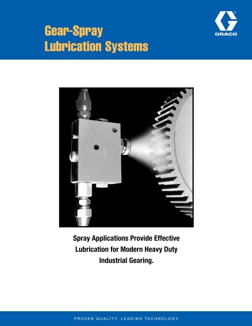
<strong>Spray</strong> Applications Provide Effective<br />
<strong>Lubrication</strong> for Modern Heavy Duty<br />
Industrial <strong>Gear</strong>ing.
Trabon ® <strong>Gear</strong>-<strong>Spray</strong> <strong>Lubrication</strong> <strong>Systems</strong><br />
DESCRIPTION<br />
Trabon provides the answer for combating wear on gear sur faces<br />
with the introduction of <strong>Gear</strong>-<strong>Spray</strong> Lubricating <strong>Systems</strong>. Hand<br />
swabbing and dip pan methods of lubricant application are now<br />
becoming obsolete. The resultant lubri cant feast or famine these<br />
application methods provide, are also becoming obsolete. Modern<br />
industrial companies are finding that spray application of lubricants<br />
to heavy duty gearing can and is eliminating over-lubrication and<br />
under-lubrication.<br />
Since Trabon has one of the finer centralized lubrication systems<br />
offered today, the inclusion of Trabon's Series Type "MS” and “MX”<br />
Divider Valves have made the <strong>Gear</strong>-<strong>Spray</strong> System a natural solution<br />
to gear spraying problems.<br />
The types of spray systems offered by Trabon are designed to<br />
provide proper coverage of gears with measured amounts of<br />
lubricant at regular intervals. <strong>Systems</strong> are totally enclosed with no<br />
external moving parts.<br />
The benefits derived from <strong>Gear</strong>-<strong>Spray</strong> lubrication are visible in<br />
neatness of installation and simplicity of design. Good housekeeping,<br />
reduction of safety hazards, extended gear life are all a reality as<br />
well as allowing lubricant dollars to be stretched as much as 75%.<br />
<strong>Gear</strong> <strong>Spray</strong> <strong>Systems</strong> are design ed for manual or automatic operation<br />
to meet the need of any application.<br />
The <strong>Gear</strong>-<strong>Spray</strong> Valve, which requires only 15 to 20 pounds of air<br />
pressure for optimum results, automatically shuts off air when<br />
lubricant feed shuts off. The combination of low air pressure and<br />
quick automatic shut-off results in substantial savings in air and<br />
lubricant<br />
<strong>Gear</strong>-<strong>Spray</strong> Valve<br />
L20141<br />
When used with a Trabon Centralized System, the <strong>Spray</strong> Valve design<br />
provides another unique feature. It automatically gives warning at<br />
the pump due to air failure or nozzle blockage.<br />
Lubricant, oil or grease, can be supplied directly from the pump, as<br />
in the case of a single isolated spray, or it can be supplied from a<br />
metering manifold or divider valve (Trabon Type MS or MX) which<br />
feeds several <strong>Gear</strong>-<strong>Spray</strong> Valves. In some cases where multi-purpose<br />
lubricant is used, bearing taps and gear sprays may be served by the<br />
same pump and manifold system. Air-lube nozzles providing normal<br />
and wide cone spray patterns are of the non-clogging external mix<br />
type. Minimum air pressure required is 20 psi, maximum is 150 psi.<br />
Installation is simple. No restriction is made as to size of air or lube<br />
supply line or length of line. 1/4" or 3/8" tubing is usually used for<br />
either line.<br />
LUBRICANT RECOMMENDATIONS<br />
• Use Number 1 grease at any temperature.<br />
• Use Number 2 grease at 32 O<br />
F. or above.<br />
• Grease must be pumpable at the encountered temperature.<br />
• Grease should not be abrasive.<br />
• Grease should resist separation.<br />
• Any oil may be used down to 100 SUS mineral oil @ 1OO O<br />
F.<br />
PANEL SELECTION METHOD<br />
N = Number of nozzles to the nearest whole number.<br />
G = Face width of gear.<br />
G<br />
N =<br />
4.6<br />
TYPICAL MANUAL SPRAY SYSTEM<br />
The <strong>Gear</strong>-<strong>Spray</strong> Valve can be used with centralized systems that are<br />
specifically planned for gear lubrication only, or it can be added to<br />
existing systems where a switch to “All Purpose” Lubricant permits<br />
both gears and bearings to be served by the same pump. In the<br />
latter case another valve or divider valve is added to the existing<br />
system to supply lubricant to the <strong>Gear</strong>-<strong>Spray</strong> Valve. The output of<br />
this added divider valve or valve is connected to the lube inlet of the<br />
spray valve and plant air, regulated to 15 to 25 PSI, is con nected to<br />
the air inlet. <strong>Spray</strong> nozzles of the flat pattern or full-cone pattern are<br />
available.<br />
Reference Description<br />
1 PH Manual Pump<br />
2 MX Divider Valve<br />
3 Cycle Counter<br />
4 <strong>Spray</strong> Valves<br />
5 Air Manifold and Gauge<br />
6 Fabricated Panel<br />
Page 2
Trabon ® <strong>Gear</strong>-<strong>Spray</strong> <strong>Lubrication</strong> <strong>Systems</strong><br />
The system illustrated is a typical basic arrangement for a manual<br />
spray system suitable for application on gears, slides, chains,<br />
etc., that require intermittent lubrication protection. The “MS” or<br />
“MX” Divider Valve is used to divide the pump output into equal<br />
or proportionate quantities depending on spray requirements. The<br />
only operation necessary is to actuate the pump handle and after<br />
counting a predetermined number of cycle indications by visual<br />
inspection, the spray lubrication cycle is complete and operator<br />
stops pumping. Optional Equipment: Totalizing counter which will<br />
keep a running total of lubrication cycles.<br />
TYPICAL<br />
AUTOMATIC<br />
SPRAY PANEL<br />
OPERATION<br />
L20141<br />
Lubricant reservoir applies a constant, nominal pressure to air<br />
pump inlet. Lubricant from 400 lb. drum enters air actuated pump.<br />
Timer actuates solenoid valves admitting air to the pump and<br />
simultaneously air is passing through the regulator to the air inlet<br />
side of the nozzles. Pump will make stroke and discharge lubricant<br />
into MX distributor which will accurately meter predetermined<br />
quantities of grease or oil to the lube inlet side of the nozzles. The<br />
air will atomize the lubricant into the desired spray pattern.<br />
The timer will de-energize the solenoid valves and allow the air<br />
circuit to exhaust. This permits the pump to return to the prime<br />
position which readies it for the next stroke.<br />
The cycle switch is actuated by the MX divider valve; this in turn is<br />
tied into the monitor panel. The monitor panel will give indication<br />
through some alarm, of a broken main line, pump failure, control<br />
failure, blockage of any tube line or nozzle, or empty reservoir.<br />
Note:<br />
• Monitor Panel is optional equipment.<br />
• Cycle Switch is optional equipment.<br />
• Cycle Switch may be used to actuate blinking lights.<br />
• This would indicate the system is working.<br />
Reference Description<br />
1 Air Filter<br />
2 Air Solenoid Valve<br />
3 Air Regulator<br />
4 Air Lubricator<br />
5 Electrical Timer (waterproof case)<br />
6 MX Divider Valve<br />
7 Fabricated Steel Panel<br />
8 <strong>Spray</strong> Nozzles<br />
9 MSA–100 Pump<br />
10 High Pressure Switch<br />
11 Speed Control Valve<br />
Reference Description<br />
1 Lubricant Feed Line<br />
2 Air<br />
3 Electrical Conduit<br />
4 Timer<br />
5 Air Operated Supply Pump<br />
6 Drum<br />
7 Air Filter and Lubricator Combo<br />
8 Air Panel<br />
9 Bull <strong>Gear</strong> Cover<br />
10 Optional Monitor Panel<br />
Page 3
TYPICAL MULTIPLE INSTALLATION<br />
Remember...<br />
Trabon <strong>Spray</strong> <strong>Lubrication</strong> Can<br />
Extend <strong>Gear</strong>-Life Three Ways<br />
1<br />
SPRAY-CONTROL VALVE PROVIDES<br />
MOST FLEXIBILITY —<br />
When supplied with lubricant under pressure the <strong>Spray</strong>-Control<br />
Valve automatically allows pressurized air to enter the mixing<br />
nozzle creating the spray pattern. This device will handle oil or<br />
grease and can be added to existing bearing lubrication systems<br />
where multi-purpose lubricants are used, or used for gear<br />
lubrication only. When lubricant metering ceases, Valve shuts off<br />
air automatically.<br />
2<br />
SPRAY NOZZLE TECHNIQUE IDEAL FOR<br />
“TIMED” HEAVY-DUTY LUBRICATION OF<br />
MILL ROLL NECKS, TABLE GEARS —<br />
Eliminating <strong>Spray</strong>-Control Valves this method employs central<br />
control of nozzle air by means of a timer-controlled air solenoid<br />
valve. The same timer can be used to energize the gear-lube<br />
pump. (If MSA or ALS Air Pump is used, pump actuation can be<br />
controlled by the same valve that supplies air to nozzles.)<br />
3<br />
COMPACT, “PACKAGED” SPRAY PANELS<br />
FOR BULL GEARS INCLUDE MSA AIR<br />
PUMP, LUBE RESERVOIR, NOZZLES<br />
AND METERING DISTRIBUTOR —<br />
Custom-fabricated to fit your bull gear, Trabon spray panels may<br />
be manually or timer-controlled. (Manual or solenoid air valve.)<br />
Panel for 1 to 6 air-lube spray nozzle is designed to fit into cutout<br />
section of gear guard. In addition to nozzles, “MS” or “MX”<br />
metering assembly, MSA Pump and Reservoir panel may also be<br />
equipped with Recorder and Air Solenoid Valve.<br />
Typical <strong>Spray</strong> Panel<br />
package may include<br />
Recorder, in addition<br />
to basic MSA Air<br />
Pump, Reservoir,<br />
Metering Assembly,<br />
<strong>Spray</strong> Nozzles and Air<br />
Pressure Regulator.<br />
All written and visual data contained in this document are based on the latest product information available at the time of publication. <strong>Graco</strong> reserves the right to make changes at any time without notice.<br />
Contact us today!<br />
To receive product information or talk with a <strong>Graco</strong> representative,<br />
call 800-533-9655 or visit us online at www.graco.com.<br />
©2006-2009 <strong>Graco</strong> <strong>Inc</strong>. Form No. L20141 Rev. B 3/09 Printed in U.S.A. All other brand names or marks are used for identification purposes and are trademarks of their respective owners. All written and<br />
visual data contained in this document are based on the latest product information available at the time of publication. <strong>Graco</strong> reserves the right to make changes at any time without notice.


