Vacuum Fittings Feedthroughs - Granzow
Vacuum Fittings Feedthroughs - Granzow
Vacuum Fittings Feedthroughs - Granzow

Create successful ePaper yourself
Turn your PDF publications into a flip-book with our unique Google optimized e-Paper software.
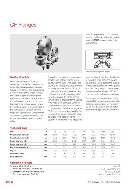
CF Flanges<br />
The CF flange connection consists of<br />
two identical flanges with a flat gasket<br />
made of OFHC copper, bolts, nuts<br />
and washers.<br />
k<br />
i.D<br />
o.D<br />
h<br />
Dimensional drawing for CF flanges<br />
Sealing Principle<br />
When assembling the CF flange<br />
connection, the flat copper gasket fits<br />
with a slight clearance into the outer<br />
recess of the flanges and thus assures<br />
good centering of the flange connection.<br />
If the flange bolts are properly<br />
tightened according to the instructions,<br />
the knife edge of the flanges penetrates<br />
into the flat copper gasket, whereby<br />
the shear action of the outer face of<br />
the cutting edge - as seen from the<br />
flange axis - produces a yield pressure<br />
on the copper gasket, while the inner<br />
face of the edge produces a cutting<br />
action.<br />
During this process the copper gasket<br />
adapts it-self optimally to the microstructure<br />
of the outer knife edge. This<br />
explains the high sealing effect and the<br />
especially low leak rates of CF flange<br />
connections. A radial grove extending<br />
right up to the sealing ring is provided<br />
for leak testing of the flange connection.<br />
In order to ensure that the sealing<br />
knife edge is not damaged during frequent<br />
use of the flanges, the conventional<br />
geometry of such knife edges for<br />
CF flanges has been developed further.<br />
By using the Leybold developed obtuse<br />
angled knife edge profile the<br />
strength of the sealing knife edges has<br />
been significantly stabilized. In addition<br />
to the actual knife edge, the flanges<br />
are provided with a concentric sealing<br />
surface for placement of a FPM gasket<br />
or a supporting ring with FPM O-ring,<br />
which may be baked up to 150 °C<br />
(does not apply to observation windows).<br />
This design has the advantage, that it<br />
is possible to equip the apparatus with<br />
elastomer gaskets prior to final assembly,<br />
so that the system can be tested<br />
under normal high vacuum conditions.<br />
Technical Data<br />
DN<br />
Outside diameter o. D.<br />
Outside diameter o. D.<br />
Inside diameter i. D.<br />
Inside diameter i. D.<br />
Bolt circle diameter k<br />
High h<br />
Number of holes<br />
Hole diameter<br />
CF<br />
inch<br />
mm<br />
inch<br />
mm<br />
mm<br />
mm<br />
mm<br />
16 40 63 100 160 200 250<br />
1.33" 2.75" 4.50" 6.00" 8.00" 10.00" 12.00"<br />
34.0 69.5 113.5 152.0 202.5 253.0 305.0<br />
0.33" 1.375" 2.50" 4.00" 6.00" 8.00" 10.00"<br />
16.0 36.8 66.0 104.0 155.0 200.0 250.0<br />
27.0 58.7 92.2 130.3 181.0 231.8 284.0<br />
7.5 13.0 17.5 20.0 22.0 24.5 24.5<br />
6 6 8 16 20 24 32<br />
4.3 6.6 8.4 8.4 8.4 8.4 8.4<br />
Conversion Factors<br />
1. Magnetizing field H, unit:<br />
Previously used unit: Oerstedt (Oe)<br />
2. Strength of the magnetic field B, unit:<br />
Previously used unit: Gauß (G)<br />
A x m -1<br />
1 Oe = 79,577 (A x m -1)<br />
Vs x m 2 = Tesla (T)<br />
1 G = 10 -4 Vs x m 2 = 10 -4 T<br />
C13 38<br />
Oerlikon Leybold <strong>Vacuum</strong> Full Line Catalog